Service Manual
Page 7
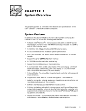
... provides an overview of the features and specifications of system memory. Jacks for a hard-disk drive in the upper PC Card connector. When used with a built-in a Dell portable computer, the Latitude CP and CPi include the following new features: A Mobile Intel® Pentium® II microprocessor 233... Support for connecting external speakers or headphones, a microphone, and record/playback devices to 128 MB of the Dell® Latitude® CP and CPi portable computers. PCI bus architecture that increases system performance. Support for use in the modular bay. A CD-ROM...
... provides an overview of the features and specifications of system memory. Jacks for a hard-disk drive in the upper PC Card connector. When used with a built-in a Dell portable computer, the Latitude CP and CPi include the following new features: A Mobile Intel® Pentium® II microprocessor 233... Support for connecting external speakers or headphones, a microphone, and record/playback devices to 128 MB of the Dell® Latitude® CP and CPi portable computers. PCI bus architecture that increases system performance. Support for use in the modular bay. A CD-ROM...
Service Manual
Page 10
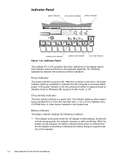
power indicator drive activity indicator battery indicator numbers lock indicator capitals lock indicator scroll lock indicator The Latitude CP or CPi computer has three indicators on the display assembly's indicator panel and three on , the power indicator lights up when ...diskette drive, CD-ROM drive, or other device installed in the modular bay. The drive activity indicator is being transferred to or from the hard-disk drive, or to -disk mode, or off , the computer is providing a maintenance (trickle) charge to keep the battery at full capacity. 1-4 Dell Latitude CP and CPi Service...
power indicator drive activity indicator battery indicator numbers lock indicator capitals lock indicator scroll lock indicator The Latitude CP or CPi computer has three indicators on the display assembly's indicator panel and three on , the power indicator lights up when ...diskette drive, CD-ROM drive, or other device installed in the modular bay. The drive activity indicator is being transferred to or from the hard-disk drive, or to -disk mode, or off , the computer is providing a maintenance (trickle) charge to keep the battery at full capacity. 1-4 Dell Latitude CP and CPi Service...
Service Manual
Page 12
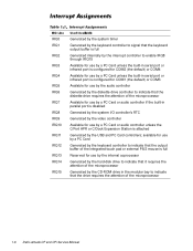
... coprocessor Generated by the hard-disk drive to indicate that it requires the attention of the microprocessor Generated by the CD-ROM drive in the modular bay to indicate that the diskette drive requires the attention of the...or audio controller unless the C/Port APR or C/Dock Expansion Station is attached Generated by the diskette drive controller to enable IRQ8 through IRQ15 Available for use by a PC Card unless the built-in serial... internally by the interrupt controller to indicate that the drive requires the attention of the microprocessor 1-6 Dell Latitude CP and CPi Service Manual
... coprocessor Generated by the hard-disk drive to indicate that it requires the attention of the microprocessor Generated by the CD-ROM drive in the modular bay to indicate that the diskette drive requires the attention of the...or audio controller unless the C/Port APR or C/Dock Expansion Station is attached Generated by the diskette drive controller to enable IRQ8 through IRQ15 Available for use by a PC Card unless the built-in serial... internally by the interrupt controller to indicate that the drive requires the attention of the microprocessor 1-6 Dell Latitude CP and CPi Service Manual
Service Manual
Page 20
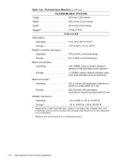
... to 10,600 m (-59 to 35,000 ft) 6 Weight shown is with the hard-disk drive in the modular bay, and one memory module. Your computer might weigh more or less, depending on its configuration. 7 Measured with a hard-disk drive, a battery in the battery bay, a diskette drive in head-parked position. 1-14 Dell Latitude CP and CPi Service Manual
... to 10,600 m (-59 to 35,000 ft) 6 Weight shown is with the hard-disk drive in the modular bay, and one memory module. Your computer might weigh more or less, depending on its configuration. 7 Measured with a hard-disk drive, a battery in the battery bay, a diskette drive in head-parked position. 1-14 Dell Latitude CP and CPi Service Manual

Service Manual
Page 32
... missing from the computer. System board faulty. One or more memory modules faulty or improperly seated. Computer needs rebooting. Hard-disk drive faulty. 3-6 Dell Latitude CP and CPi Service Manual Computer cannot identify hard-disk drive type. Installed hard-disk drive not compatible with computer. Computer cannot enable protective mode. System board faulty. The diskette may be completed. Diskette writeprotected...
... missing from the computer. System board faulty. One or more memory modules faulty or improperly seated. Computer needs rebooting. Hard-disk drive faulty. 3-6 Dell Latitude CP and CPi Service Manual Computer cannot identify hard-disk drive type. Installed hard-disk drive not compatible with computer. Computer cannot enable protective mode. System board faulty. The diskette may be completed. Diskette writeprotected...

Service Manual
Page 34
... properly. ROM in external device faulty. Optional ROM in external device failed. Timer on diskette or hard-disk drive. 3-8 Dell Latitude CP and CPi Service Manual Bad sector or corrupted FAT on system board malfunctioning. No boot sector on hard-disk drive or diskette. Installed memory module faulty or improperly seated. No boot device available. No operating system...
... properly. ROM in external device faulty. Optional ROM in external device failed. Timer on diskette or hard-disk drive. 3-8 Dell Latitude CP and CPi Service Manual Bad sector or corrupted FAT on system board malfunctioning. No boot sector on hard-disk drive or diskette. Installed memory module faulty or improperly seated. No boot device available. No operating system...

Service Manual
Page 48
...ZPS LCD hinge LCD inverter board LCD bezel and latch, 12.1-inch display Keyboard Thermal cooling assembly Touch-pad Palmrest, front edge Palmrest, hard-disk drive area I/R board Upper EMI shield, 1st PC/Video board Back cover Audio board Upper EMI shield, 2nd Bottom-case bracket Exhaust fan...board assembly with system board and processor module ASSY,PRM/PWA,ENGINE, CPxxx* * Substitute the drive capacity for xxxxx, the drive height for yy, and the manufacturer for zzz. 4-18, 4-19 4-16 4-21 4-17 4-9 4-30 4-13 4-12 4-12 4-32 4-11 4-26 4-27 4-31 4-30 4-12 Dell Latitude CP and CPi Service Manual
...ZPS LCD hinge LCD inverter board LCD bezel and latch, 12.1-inch display Keyboard Thermal cooling assembly Touch-pad Palmrest, front edge Palmrest, hard-disk drive area I/R board Upper EMI shield, 1st PC/Video board Back cover Audio board Upper EMI shield, 2nd Bottom-case bracket Exhaust fan...board assembly with system board and processor module ASSY,PRM/PWA,ENGINE, CPxxx* * Substitute the drive capacity for xxxxx, the drive height for yy, and the manufacturer for zzz. 4-18, 4-19 4-16 4-21 4-17 4-9 4-30 4-13 4-12 4-12 4-32 4-11 4-26 4-27 4-31 4-30 4-12 Dell Latitude CP and CPi Service Manual
Service Manual
Page 78
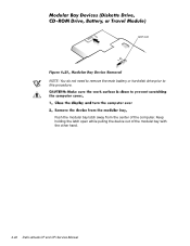
latch lock NOTE: You do not need to remove the main battery or hard-disk drive prior to this procedure. Keep holding the latch open while pulling the device out of the computer. Push the modular bay latch away from the center of the modular bay with the other hand. 4-42 Dell Latitude CP and CPi Service Manual
latch lock NOTE: You do not need to remove the main battery or hard-disk drive prior to this procedure. Keep holding the latch open while pulling the device out of the computer. Push the modular bay latch away from the center of the modular bay with the other hand. 4-42 Dell Latitude CP and CPi Service Manual
Service Manual
Page 88
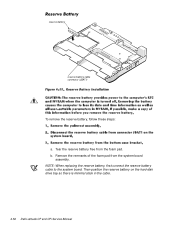
Tear the reserve battery free from the system board assembly. Remove the remnants of the foam pad from the foam pad. Then position the reserve battery on the hard-disk drive bay so there is minimal slack in the cable. 4-52 Dell Latitude CP and CPi Service Manual NOTE: When replacing the reserve battery, first connect the reserve battery cable to the system board. reserve battery reserve battery cable connector (JBAT1) To remove the reserve battery, follow these steps: a. b.
Tear the reserve battery free from the system board assembly. Remove the remnants of the foam pad from the foam pad. Then position the reserve battery on the hard-disk drive bay so there is minimal slack in the cable. 4-52 Dell Latitude CP and CPi Service Manual NOTE: When replacing the reserve battery, first connect the reserve battery cable to the system board. reserve battery reserve battery cable connector (JBAT1) To remove the reserve battery, follow these steps: a. b.
Service Manual
Page 90
..., 4-14 list of, 4-5 hard-disk drive assembly removal, 4-15 help getting, 2-6 I/O panel, 1-3 I/R board removal, 4-51 indicator panel, 1-4 initial procedures system error messages, 3-5 troubleshooting, 2-1 initialization error messages, 3-10 interrupt assignments list of, 1-6 keyboard assembly removal, 4-18 keyboard indicators, 1-5 LCD display hinge removal, 4-38 LCD inverter board removal, 4-35, 4-36 2 Dell Latitude CP and CPi Service Manual LCD...
..., 4-14 list of, 4-5 hard-disk drive assembly removal, 4-15 help getting, 2-6 I/O panel, 1-3 I/R board removal, 4-51 indicator panel, 1-4 initial procedures system error messages, 3-5 troubleshooting, 2-1 initialization error messages, 3-10 interrupt assignments list of, 1-6 keyboard assembly removal, 4-18 keyboard indicators, 1-5 LCD display hinge removal, 4-38 LCD inverter board removal, 4-35, 4-36 2 Dell Latitude CP and CPi Service Manual LCD...
Replacement Instructions
Page 9
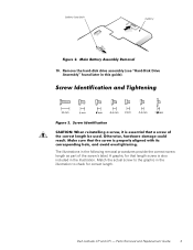
Match the actual screw to check for that length screw is also included in the illustration to the graphic in the illustration. Parts Removal and Replacement Guide 3 battery bay latch battery 10. A graphic for correct length. Dell Latitude CP and CPi - The illustrations in this guide). Remove the hard-disk drive assembly (see "Hard-Disk Drive Assembly" found later in the following removal procedures provide the correct screw length as part of the screw's label.
Match the actual screw to check for that length screw is also included in the illustration to the graphic in the illustration. Parts Removal and Replacement Guide 3 battery bay latch battery 10. A graphic for correct length. Dell Latitude CP and CPi - The illustrations in this guide). Remove the hard-disk drive assembly (see "Hard-Disk Drive Assembly" found later in the following removal procedures provide the correct screw length as part of the screw's label.

Replacement Instructions
Page 13
... 7 Dell Latitude CP and CPi - Hard-disk drive, subassembly SUBASSY,HD,xxxxx,I,yyyMM, 6 CP* Hard-disk drive HD,xxxxx,I,yyMM,NBK,zzz* Hard-disk drive interface PWA,INTERCONN,HD,CP board Hard-disk drive bracket BRKT,HD,CP Hard-disk drive carrier SVC,ASSY,BRKT/DOOR, 6 bracket/door assembly HD,CP service kit Hard-disk drive carrier door DOOR,HD,12.5MM,CP Hard-disk drive carrier bracket BRKT,HD,12.5MM,CP Hard-disk drive...
... 7 Dell Latitude CP and CPi - Hard-disk drive, subassembly SUBASSY,HD,xxxxx,I,yyyMM, 6 CP* Hard-disk drive HD,xxxxx,I,yyMM,NBK,zzz* Hard-disk drive interface PWA,INTERCONN,HD,CP board Hard-disk drive bracket BRKT,HD,CP Hard-disk drive carrier SVC,ASSY,BRKT/DOOR, 6 bracket/door assembly HD,CP service kit Hard-disk drive carrier door DOOR,HD,12.5MM,CP Hard-disk drive carrier bracket BRKT,HD,12.5MM,CP Hard-disk drive...

Replacement Instructions
Page 18
...,US,LXP System board assembly with system board and processor module ASSY,PRM/PWA,ENGINE, CPxxx* * Substitute the drive capacity for xxxxx, the drive height for yy, and the manufacturer for zzz. 12 Dell Latitude CP and CPi - LCD panel SCR,M3X5,PHH,LP,ZPS 18, 19 LCD hinge SCR,M3X5,PHH,LP,ZPS 16 LCD...,M2X2.5,PHH,LP,ZPS 30 Touch-pad SCR,M2.6X1.8,PHH,XLP,ZPS 13 Palmrest, front edge SCR,M2.6X12,PHH,LP,ZPS 12 Palmrest, hard-disk drive SCR,M2.6X5,PHH,LP,ZPS 12 area I/R board SCR,M2.6X5,PHH,LP,ZPS 34 Upper EMI shield, 1st SCR,M2.6X5,PHH...
...,US,LXP System board assembly with system board and processor module ASSY,PRM/PWA,ENGINE, CPxxx* * Substitute the drive capacity for xxxxx, the drive height for yy, and the manufacturer for zzz. 12 Dell Latitude CP and CPi - LCD panel SCR,M3X5,PHH,LP,ZPS 18, 19 LCD hinge SCR,M3X5,PHH,LP,ZPS 16 LCD...,M2X2.5,PHH,LP,ZPS 30 Touch-pad SCR,M2.6X1.8,PHH,XLP,ZPS 13 Palmrest, front edge SCR,M2.6X12,PHH,LP,ZPS 12 Palmrest, hard-disk drive SCR,M2.6X5,PHH,LP,ZPS 12 area I/R board SCR,M2.6X5,PHH,LP,ZPS 34 Upper EMI shield, 1st SCR,M2.6X5,PHH...

Replacement Instructions
Page 21
Turn the computer over, and remove the two 5-mm screws from the hard-disk drive door. Dell Latitude CP and CPi - Grasp the drive door and pull the drive out of the computer. 2. 5-mm screws (2) hard-disk drive door 1. Parts Removal and Replacement Guide 15 The drive is on the left side of the computer.
Turn the computer over, and remove the two 5-mm screws from the hard-disk drive door. Dell Latitude CP and CPi - Grasp the drive door and pull the drive out of the computer. 2. 5-mm screws (2) hard-disk drive door 1. Parts Removal and Replacement Guide 15 The drive is on the left side of the computer.

Replacement Instructions
Page 27
...back cover assembly. 4. Disconnect the touch-pad cable from ZIF connector JP2 on the system board. 3. The palmrest assembly consists of the computer Dell Latitude CP and CPi - palmrest assembly 5-mm screws (2) 5-mm screw bottom case assembly 12-mm screws (3) 1. Remove the keyboard. 2. Parts Removal and Replacement Guide... inside the computer, adjacent to the thermal cooling assembly Two 5-mm screws inside the upper edge of the hard-disk drive bay (you must remove the hard-disk drive to access these screws) Three 12-mm screws underneath the front edge of the touch pad and the palmrest...
...back cover assembly. 4. Disconnect the touch-pad cable from ZIF connector JP2 on the system board. 3. The palmrest assembly consists of the computer Dell Latitude CP and CPi - palmrest assembly 5-mm screws (2) 5-mm screw bottom case assembly 12-mm screws (3) 1. Remove the keyboard. 2. Parts Removal and Replacement Guide... inside the computer, adjacent to the thermal cooling assembly Two 5-mm screws inside the upper edge of the hard-disk drive bay (you must remove the hard-disk drive to access these screws) Three 12-mm screws underneath the front edge of the touch pad and the palmrest...
Replacement Instructions
Page 44
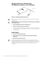
..., ensure that the audio shield is properly seated to this by temporarily installing a device in the modular bay prior to reinstalling the palmrest assembly.) 38 Dell Latitude CP and CPi - Remove the 5-mm screw securing the audio board shield (see Figure 26). 3. latch lock NOTE: You do not need to remove the main battery...
..., ensure that the audio shield is properly seated to this by temporarily installing a device in the modular bay prior to reinstalling the palmrest assembly.) 38 Dell Latitude CP and CPi - Remove the 5-mm screw securing the audio board shield (see Figure 26). 3. latch lock NOTE: You do not need to remove the main battery...

Replacement Instructions
Page 55
Remove the remnants of the foam pad from connector JBAT1 on the hard-disk drive bay so there is minimal slack in the cable. Dell Latitude CP and CPi - reserve battery reserve battery cable connector (JBAT1) To remove the reserve battery, follow these steps: 1. Then position the reserve battery on the system board. 3. Parts ...
Remove the remnants of the foam pad from connector JBAT1 on the hard-disk drive bay so there is minimal slack in the cable. Dell Latitude CP and CPi - reserve battery reserve battery cable connector (JBAT1) To remove the reserve battery, follow these steps: 1. Then position the reserve battery on the system board. 3. Parts ...


