Service Manual
Page 4
... 4-37 LCD Display Hinge 4-38 Display-Assembly Top Cover 4-39 Bottom Case Assembly 4-40 Modular Bay Devices (Diskette Drive, CD-ROM Drive, Battery, or Travel Module 4-42 Audio Shield 4-43 Audio Board 4-44 Bottom Case Bracket 4-45 Module Latch Assemblies 4-46 Speakers 4-47 System Board Assembly 4-48 Exhaust Fan 4-50 I/R Board 4-51 Reserve...
... 4-37 LCD Display Hinge 4-38 Display-Assembly Top Cover 4-39 Bottom Case Assembly 4-40 Modular Bay Devices (Diskette Drive, CD-ROM Drive, Battery, or Travel Module 4-42 Audio Shield 4-43 Audio Board 4-44 Bottom Case Bracket 4-45 Module Latch Assemblies 4-46 Speakers 4-47 System Board Assembly 4-48 Exhaust Fan 4-50 I/R Board 4-51 Reserve...
Service Manual
Page 5
...Identification 4-3 Disconnecting an Interface Cable 4-4 Exploded View-Computer 4-14 Hard-Disk Drive Assembly Removal 4-15 Memory Module Cover Removal 4-16 Memory Module Removal 4-17 Removing the Keyboard Assembly Screws 4-18 Keyboard Assembly Removal 4-19 Back Cover Assembly Removal 4-20 ...4-42 Audio Board Removal 4-44 Bottom Case Bracket Removal 4-45 Module Latch Assemblies Removal 4-46 Left Slider 4-47 System Board Assembly Removal 4-48 Exhaust Fan Removal 4-50 I/R Board Removal 4-51 Reserve Battery Installation 4-52 Table 1-1. Figure 4-14. Figure 4-18. Figure ...
...Identification 4-3 Disconnecting an Interface Cable 4-4 Exploded View-Computer 4-14 Hard-Disk Drive Assembly Removal 4-15 Memory Module Cover Removal 4-16 Memory Module Removal 4-17 Removing the Keyboard Assembly Screws 4-18 Keyboard Assembly Removal 4-19 Back Cover Assembly Removal 4-20 ...4-42 Audio Board Removal 4-44 Bottom Case Bracket Removal 4-45 Module Latch Assemblies Removal 4-46 Left Slider 4-47 System Board Assembly Removal 4-48 Exhaust Fan Removal 4-50 I/R Board Removal 4-51 Reserve Battery Installation 4-52 Table 1-1. Figure 4-14. Figure 4-18. Figure ...
Service Manual
Page 9
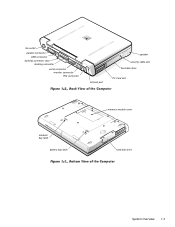
fan outlet parallel connector USB connector docking connector door docking connector serial connector monitor connector PS2 connector infrared port speaker security cable slot hard-disk drive PC Card slot modular bay latch battery bay latch memory module cover hard-disk drive System Overview 1-3
fan outlet parallel connector USB connector docking connector door docking connector serial connector monitor connector PS2 connector infrared port speaker security cable slot hard-disk drive PC Card slot modular bay latch battery bay latch memory module cover hard-disk drive System Overview 1-3
Service Manual
Page 19
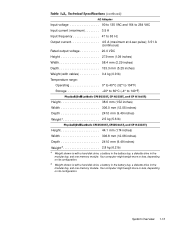
....0 mm (9.49 inches) Weight5 2.8 kg (6.2 lb) 4 Weight shown is with a hard-disk drive, a battery in the battery bay, a diskette drive in the modular bay, and one memory module. Your computer might weigh more or less, depending on its configuration. 5 Weight shown is with a hard-disk ...drive, a battery in the battery bay, a diskette drive in the modular bay, and one memory module. System Overview 1-13 Your computer might ...
....0 mm (9.49 inches) Weight5 2.8 kg (6.2 lb) 4 Weight shown is with a hard-disk drive, a battery in the battery bay, a diskette drive in the modular bay, and one memory module. Your computer might weigh more or less, depending on its configuration. 5 Weight shown is with a hard-disk ...drive, a battery in the battery bay, a diskette drive in the modular bay, and one memory module. System Overview 1-13 Your computer might ...
Service Manual
Page 20
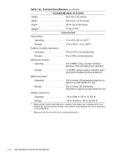
Your computer might weigh more or less, depending on its configuration. 7 Measured with a hard-disk drive, a battery in the battery bay, a diskette drive in head-parked position. 1-14 Dell Latitude CP and CPi Service Manual Height 38.6 mm (1.52 inches) Width 306.0 mm (12.05 inches) Depth 241.0 mm (9.49 inches) Weight6 2.6 kg (5.8 lb) Temperature: Operating...) Storage 18 to 10,600 m (-59 to 35,000 ft) 6 Weight shown is with the hard-disk drive in the modular bay, and one memory module.
Your computer might weigh more or less, depending on its configuration. 7 Measured with a hard-disk drive, a battery in the battery bay, a diskette drive in head-parked position. 1-14 Dell Latitude CP and CPi Service Manual Height 38.6 mm (1.52 inches) Width 306.0 mm (12.05 inches) Depth 241.0 mm (9.49 inches) Weight6 2.6 kg (5.8 lb) Temperature: Operating...) Storage 18 to 10,600 m (-59 to 35,000 ft) 6 Weight shown is with the hard-disk drive in the modular bay, and one memory module.
Service Manual
Page 29
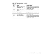
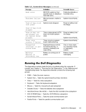
4-3-1 4-3-3 4-3-4 4-4-1 5-1-2 Memory failure above address 0FFFFh Timer chip counter 2 failure Time-of-day clock stopped Serial port failure No usable memory Memory module improperly seated or system memory controller faulty (system board faulty) System board faulty Reserve battery faulty or system board faulty System board faulty Memory module improperly seated or system memory controller faulty (system board faulty) System Error Messages 3-3
4-3-1 4-3-3 4-3-4 4-4-1 5-1-2 Memory failure above address 0FFFFh Timer chip counter 2 failure Time-of-day clock stopped Serial port failure No usable memory Memory module improperly seated or system memory controller faulty (system board faulty) System board faulty Reserve battery faulty or system board faulty System board faulty Memory module improperly seated or system memory controller faulty (system board faulty) System Error Messages 3-3
Service Manual
Page 33
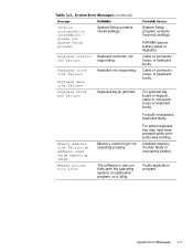
...invalid settings. Keyboard clock line failure Keyboard data line failure Keyboard stuck key failure Keyboard not responding. The software in keyboard, keyboard faulty. NVRAM reserve battery weak or depleted. For either keyboard, key may have been pressed while computer was booting. Keyboard controller not ler failure responding. Keyboard control- For ...Cable or connector loose, or keyboard faulty. Faulty application program. Cable or connector loose, or keyboard faulty. System Error Messages 3-7 Keyboard key(s) jammed. Installed memory module faulty or improperly seated.
...invalid settings. Keyboard clock line failure Keyboard data line failure Keyboard stuck key failure Keyboard not responding. The software in keyboard, keyboard faulty. NVRAM reserve battery weak or depleted. For either keyboard, key may have been pressed while computer was booting. Keyboard controller not ler failure responding. Keyboard control- For ...Cable or connector loose, or keyboard faulty. Faulty application program. Cable or connector loose, or keyboard faulty. System Error Messages 3-7 Keyboard key(s) jammed. Installed memory module faulty or improperly seated.
Service Manual
Page 35
... on diskette or hard-disk drive. If needed, see Chapter 4, "Running the Dell Diagnostics," in troubleshooting the computer. Tests the IDE hard-disk drive subsystem IDE CD ROM Drives - Keyboard/mouse controller malfunctioning, or memory module(s) not responding. Reserve battery lost power MS-DOS unable to System board faulty. The diagnostics contains tests...
... on diskette or hard-disk drive. If needed, see Chapter 4, "Running the Dell Diagnostics," in troubleshooting the computer. Tests the IDE hard-disk drive subsystem IDE CD ROM Drives - Keyboard/mouse controller malfunctioning, or memory module(s) not responding. Reserve battery lost power MS-DOS unable to System board faulty. The diagnostics contains tests...

Service Manual
Page 49
... processor module System-board engine subassembly I/R board Microphone boot Main system board Video/PC Card board LED board Lower EMI shield Upper EMI shield, 1st Upper EMI shield, 2nd Exhaust fan and cable Microphone Reserve battery Foam pad ASSY,PRM/PWA,ENGINE, CPixxx* SUBASSY,PWA/ENGINE,CP PWA,FAST IR,CP GRMT,...RBR,BOOT,MCPHN PWA,PLN,0M,NB,CP PWA,DTRBD,VID/PCMCIA,CP PWA,LED,CP SHLD,BTM,PLN ASSY,CP SHLD,TOP,1ST,PLN ASSY,CP SHLD,TOP,2ND,PLN ASSY,CP FAN,25X25X10,CP MCPHN,CP BTRY,RSRV...
... processor module System-board engine subassembly I/R board Microphone boot Main system board Video/PC Card board LED board Lower EMI shield Upper EMI shield, 1st Upper EMI shield, 2nd Exhaust fan and cable Microphone Reserve battery Foam pad ASSY,PRM/PWA,ENGINE, CPixxx* SUBASSY,PWA/ENGINE,CP PWA,FAST IR,CP GRMT,...RBR,BOOT,MCPHN PWA,PLN,0M,NB,CP PWA,DTRBD,VID/PCMCIA,CP PWA,LED,CP SHLD,BTM,PLN ASSY,CP SHLD,TOP,1ST,PLN ASSY,CP SHLD,TOP,2ND,PLN ASSY,CP FAN,25X25X10,CP MCPHN,CP BTRY,RSRV...
Service Manual
Page 76
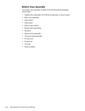
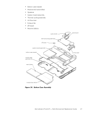
The bottom case assembly consists of the following field-replaceable components: Diskette drive assembly, CD-ROM drive assembly, or travel module Back cover assembly Audio shield Audio board Bottom case bracket Module latch assemblies Speakers System board assembly Thermal cooling assembly Air flow duct Exhaust fan I/R board Reserve battery 4-40 Dell Latitude CP and CPi Service Manual
The bottom case assembly consists of the following field-replaceable components: Diskette drive assembly, CD-ROM drive assembly, or travel module Back cover assembly Audio shield Audio board Bottom case bracket Module latch assemblies Speakers System board assembly Thermal cooling assembly Air flow duct Exhaust fan I/R board Reserve battery 4-40 Dell Latitude CP and CPi Service Manual

Service Manual
Page 77
audio shield thermal cooling assembly I/R board system board assembly bottom case bracket module latch assembly (2) main battery audio board air flow duct modular bay device Removing and Replacing Parts 4-41
audio shield thermal cooling assembly I/R board system board assembly bottom case bracket module latch assembly (2) main battery audio board air flow duct modular bay device Removing and Replacing Parts 4-41
Service Manual
Page 85
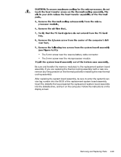
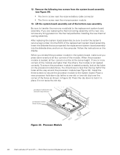
The 5-mm screw near the reserve-battery cable connector The 5-mm screw near the microprocessor module Be sure and transfer the memory module(s) to enter the system's service tag number into the diskette drive, and turn on the computer. Follow the instructions on the thermal pad before installing ...
The 5-mm screw near the reserve-battery cable connector The 5-mm screw near the microprocessor module Be sure and transfer the memory module(s) to enter the system's service tag number into the diskette drive, and turn on the computer. Follow the instructions on the thermal pad before installing ...
Service Manual
Page 90
..., 1-6 keyboard assembly removal, 4-18 keyboard indicators, 1-5 LCD display hinge removal, 4-38 LCD inverter board removal, 4-35, 4-36 2 Dell Latitude CP and CPi Service Manual LCD panel removal, 4-31, 4-32 LEDs, 1-4 low-battery warnings, 1-4 main battery assembly removal, 4-3 memory module removal, 4-17 memory module cover removal, 4-16 messages, system error about, 3-5 list of, 3-5 modular bay devices removal, 4-42...
..., 1-6 keyboard assembly removal, 4-18 keyboard indicators, 1-5 LCD display hinge removal, 4-38 LCD inverter board removal, 4-35, 4-36 2 Dell Latitude CP and CPi Service Manual LCD panel removal, 4-31, 4-32 LEDs, 1-4 low-battery warnings, 1-4 main battery assembly removal, 4-3 memory module removal, 4-17 memory module cover removal, 4-16 messages, system error about, 3-5 list of, 3-5 modular bay devices removal, 4-42...

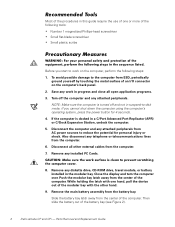
Replacement Instructions
Page 3
...Parts and Assemblies 5 Removing Field-Replaceable Parts and Assemblies 14 Hard-Disk Drive Assembly 15 Memory Module Cover 16 Memory Modules 17 Keyboard Assembly 18 Back Cover Assembly 20 Palmrest Assembly 21 Touch-Pad Interface Module 23 Power Button 24 Display Assembly Components 24 Display Assembly 27 Display Assembly Bezel 28 Display ...Assembly Interface Cable 35 LCD Display Hinge 35 Display-Assembly Top Cover 36 Bottom Case Assembly 36 Modular Bay Devices (Diskette Drive, CD-ROM Drive, Battery, or Travel Module 38 Audio Shield 38 Audio Board 39 Bottom Case Bracket 40 iii
...Parts and Assemblies 5 Removing Field-Replaceable Parts and Assemblies 14 Hard-Disk Drive Assembly 15 Memory Module Cover 16 Memory Modules 17 Keyboard Assembly 18 Back Cover Assembly 20 Palmrest Assembly 21 Touch-Pad Interface Module 23 Power Button 24 Display Assembly Components 24 Display Assembly 27 Display Assembly Bezel 28 Display ...Assembly Interface Cable 35 LCD Display Hinge 35 Display-Assembly Top Cover 36 Bottom Case Assembly 36 Modular Bay Devices (Diskette Drive, CD-ROM Drive, Battery, or Travel Module 38 Audio Shield 38 Audio Board 39 Bottom Case Bracket 40 iii

Replacement Instructions
Page 4
... Figure 13. Figure 21. Figure 23. Figure 24. Figure 25. Figure 30. Module Latch Assemblies 41 Speakers 42 System Board Assembly 43 Exhaust Fan 47 I/R Board 48 Reserve Battery 49 Figure 1. Figure 12. Figure 18. Figure 5. Figure 17. Figure 20. ... Figure 9. Figure 3. Computer Orientation 1 Main Battery Assembly Removal 3 Screw Identification 3 Disconnecting an Interface Cable 4 Exploded View-Computer 14 Hard-Disk Drive Assembly Removal 15 Memory Module Cover Removal 16 Memory Module Removal 17 Keyboard Assembly Screws Removal 18 Keyboard ...
... Figure 13. Figure 21. Figure 23. Figure 24. Figure 25. Figure 30. Module Latch Assemblies 41 Speakers 42 System Board Assembly 43 Exhaust Fan 47 I/R Board 48 Reserve Battery 49 Figure 1. Figure 12. Figure 18. Figure 5. Figure 17. Figure 20. ... Figure 9. Figure 3. Computer Orientation 1 Main Battery Assembly Removal 3 Screw Identification 3 Disconnecting an Interface Cable 4 Exploded View-Computer 14 Hard-Disk Drive Assembly Removal 15 Memory Module Cover Removal 16 Memory Module Removal 17 Keyboard Assembly Screws Removal 18 Keyboard ...

Replacement Instructions
Page 5
Parts and Assemblies 5 v Figure 31. One- Figure 32. Figure 34. and Two-Slot Processor Hold-Down Clips 45 Processor Module 46 Exhaust Fan Removal 47 I/R Board Removal 48 Reserve Battery Installation 49 Table 1. Figure 35. Figure 33.
Parts and Assemblies 5 v Figure 31. One- Figure 32. Figure 34. and Two-Slot Processor Hold-Down Clips 45 Processor Module 46 Exhaust Fan Removal 47 I/R Board Removal 48 Reserve Battery Installation 49 Table 1. Figure 35. Figure 33.
Replacement Instructions
Page 8
..., pull the device out of the modular bay with one or more of the battery bay (see Figure 2). 2 Dell Latitude CP and CPi - If the computer is turned off the computer and any diskette drive, CD-ROM drive, travel module, or battery installed in a C/Port Advanced Port Replicator (APR) or C/Dock Expansion Station, undock the computer...
..., pull the device out of the modular bay with one or more of the battery bay (see Figure 2). 2 Dell Latitude CP and CPi - If the computer is turned off the computer and any diskette drive, CD-ROM drive, travel module, or battery installed in a C/Port Advanced Port Replicator (APR) or C/Dock Expansion Station, undock the computer...

Replacement Instructions
Page 19
...,CP MCPHN,CP BTRY,RSRV,7.2,30MAH,6,NIHD PAD,FOAM,BTRY,RSRV,CP Service kit, thermal cooling SVC,SUBASSY,HTSNK, 30 subassembly CPU,HYB,CP Touch-pad service kit SVC,TPAD,SQ,INTFC,CP 13 Touch-pad subassembly TPA,INTFC,CP * Substitute the drive capacity for xxxxx, the drive height for yy, and the manufacturer for zzz. Dell Latitude CP...
...,CP MCPHN,CP BTRY,RSRV,7.2,30MAH,6,NIHD PAD,FOAM,BTRY,RSRV,CP Service kit, thermal cooling SVC,SUBASSY,HTSNK, 30 subassembly CPU,HYB,CP Touch-pad service kit SVC,TPAD,SQ,INTFC,CP 13 Touch-pad subassembly TPA,INTFC,CP * Substitute the drive capacity for xxxxx, the drive height for yy, and the manufacturer for zzz. Dell Latitude CP...
Replacement Instructions
Page 43
Parts Removal and Replacement Guide 37 Bottom case bracket Module latch assemblies Speakers System board assembly Thermal cooling assembly Air flow duct Exhaust fan I/R board Reserve battery audio shield thermal cooling assembly I/R board system board assembly bottom case bracket module latch assembly (2) main battery audio board air flow duct modular bay device Dell Latitude CP and CPi -
Parts Removal and Replacement Guide 37 Bottom case bracket Module latch assemblies Speakers System board assembly Thermal cooling assembly Air flow duct Exhaust fan I/R board Reserve battery audio shield thermal cooling assembly I/R board system board assembly bottom case bracket module latch assembly (2) main battery audio board air flow duct modular bay device Dell Latitude CP and CPi -
Replacement Instructions
Page 52
... at all the way around the processor module (see Figure 32). Follow the instructions on the processor-module fence. If one -slot clip shown) processor-module fence holes 46 Dell Latitude CP and CPi - Do not reuse the old clip. When the processor module is seated, all four corners must be...same height. Install the three screws to secure the processor module to lock it in place. You should see Figure 30): The 5-mm screw near the reserve-battery cable connector The 5-mm screw near the microprocessor module 13. Insert the diskette that accompanied the replacement system ...
... at all the way around the processor module (see Figure 32). Follow the instructions on the processor-module fence. If one -slot clip shown) processor-module fence holes 46 Dell Latitude CP and CPi - Do not reuse the old clip. When the processor module is seated, all four corners must be...same height. Install the three screws to secure the processor module to lock it in place. You should see Figure 30): The 5-mm screw near the reserve-battery cable connector The 5-mm screw near the microprocessor module 13. Insert the diskette that accompanied the replacement system ...


