Quick Reference Guide
Page 5
...to provide last-minute updates about technical changes to troubleshoot and solve problems Dell Latitude™ User's Guide Microsoft Windows Help and Support Center 1 Click Start or → Help and Support→ Dell User and System Guides→ System Guides. Documentation and drivers are .... NOTE: Additional information may be included on your computer. Readme files may ship with your computer. Dell™ Product Information Guide • How to remove and replace parts • Specifications • How to configure system settings • How to your computer or advanced...
...to provide last-minute updates about technical changes to troubleshoot and solve problems Dell Latitude™ User's Guide Microsoft Windows Help and Support Center 1 Click Start or → Help and Support→ Dell User and System Guides→ System Guides. Documentation and drivers are .... NOTE: Additional information may be included on your computer. Readme files may ship with your computer. Dell™ Product Information Guide • How to remove and replace parts • Specifications • How to configure system settings • How to your computer or advanced...
User's Guide
Page 8
... or Mouse Problems 100 Video and Display Problems 100 If the display is blank 101 If the display is difficult to read 101 If only part of the display is readable 102 12 System Setup Program Overview 103 Viewing the System Setup Screens 103 System Setup Screens 104 Commonly Used Options...
... or Mouse Problems 100 Video and Display Problems 100 If the display is blank 101 If the display is difficult to read 101 If only part of the display is readable 102 12 System Setup Program Overview 103 Viewing the System Setup Screens 103 System Setup Screens 104 Commonly Used Options...
User's Guide
Page 9
... Vista 111 Restoring Your Operating System 111 Using Microsoft® Windows® System Restore 111 Using the Operating System Media 112 14 Adding and Replacing Parts Before You Begin 115 Recommended Tools 115 Turning Off Your Computer 115 Before Working Inside Your Computer 116 Hinge Cover 118 Keyboard 119 Internal Card... 122 Wireless Local Area Network (WLAN) Card 127 Mobile Broadband Card 129 Subscriber Identity Module (SIM) Card 132 Hard Drive 132 Returning a Hard Drive to Dell 134 Media Bay 135 Removing Media Bay Devices 135 FCM (Flash Cache Module) Card 135 15...
... Vista 111 Restoring Your Operating System 111 Using Microsoft® Windows® System Restore 111 Using the Operating System Media 112 14 Adding and Replacing Parts Before You Begin 115 Recommended Tools 115 Turning Off Your Computer 115 Before Working Inside Your Computer 116 Hinge Cover 118 Keyboard 119 Internal Card... 122 Wireless Local Area Network (WLAN) Card 127 Mobile Broadband Card 129 Subscriber Identity Module (SIM) Card 132 Hard Drive 132 Returning a Hard Drive to Dell 134 Media Bay 135 Removing Media Bay Devices 135 FCM (Flash Cache Module) Card 135 15...
User's Guide
Page 77
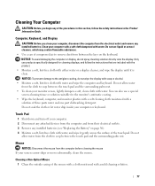
Computer, Keyboard, and Display CAUTION: Before you begin any of three parts water and one part dishwashing detergent. Do not allow water from the cloth to remove dust from between the keys on page 36). 4 Moisten a soft, lint-free cloth with a ...
Computer, Keyboard, and Display CAUTION: Before you begin any of three parts water and one part dishwashing detergent. Do not allow water from the cloth to remove dust from between the keys on page 36). 4 Moisten a soft, lint-free cloth with a ...

User's Guide
Page 83
... top of devices. Lists the most common symptoms encountered and allows you to select a test based on page 149). If you contact Dell, technical support will ask for your part. Troubleshooting 83 Displays error conditions encountered, error codes, and the problem description. Performs a thorough check of each test screen. If you want...
... top of devices. Lists the most common symptoms encountered and allows you to select a test based on page 149). If you contact Dell, technical support will ask for your part. Troubleshooting 83 Displays error conditions encountered, error codes, and the problem description. Performs a thorough check of each test screen. If you want...

User's Guide
Page 102
If only part of the display is readable CONNECT AN EXTERNAL MONITOR - 1 Shut down your computer and connect an external monitor to the computer. 2 Turn on page 149). 102 Troubleshooting If the external monitor works, the computer display or video controller may be defective. Contact Dell (see "Obtaining Assistance" on the computer and the monitor and adjust the monitor brightness and contrast controls.
If only part of the display is readable CONNECT AN EXTERNAL MONITOR - 1 Shut down your computer and connect an external monitor to the computer. 2 Turn on page 149). 102 Troubleshooting If the external monitor works, the computer display or video controller may be defective. Contact Dell (see "Obtaining Assistance" on the computer and the monitor and adjust the monitor brightness and contrast controls.

User's Guide
Page 115
...Adding and Replacing Parts 115 Unless otherwise noted, each procedure assumes that the computer and any open files, exit any attached devices are turned off your operating system, press and hold the power button for removing and installing the components in your Dell™ Product Information...→ Shut down→ OK. If your computer and attached devices did not automatically turn off . 15 Adding and Replacing Parts Before You Begin This chapter provides procedures for 4 seconds. Recommended Tools The procedures in this document may require the following conditions exist...
...Adding and Replacing Parts 115 Unless otherwise noted, each procedure assumes that the computer and any open files, exit any attached devices are turned off your operating system, press and hold the power button for removing and installing the components in your Dell™ Product Information...→ Shut down→ OK. If your computer and attached devices did not automatically turn off . 15 Adding and Replacing Parts Before You Begin This chapter provides procedures for 4 seconds. Recommended Tools The procedures in this document may require the following conditions exist...

User's Guide
Page 116
...procedures in this type of cable, press in the Product Information Guide. See the documentation that could harm internal components. 116 Adding and Replacing Parts NOTICE: To disconnect a network cable, first unplug the cable from your computer and then unplug it from the network wall connector. 4 ... the following safety guidelines to help ensure your computer (see "Replacing the Battery" on page 115). 3 If the computer is not covered by Dell is connected to ground the system board. 10 Remove the computer stand, if it . CAUTION: To guard against electrical shock, always unplug your...
...procedures in this type of cable, press in the Product Information Guide. See the documentation that could harm internal components. 116 Adding and Replacing Parts NOTICE: To disconnect a network cable, first unplug the cable from your computer and then unplug it from the network wall connector. 4 ... the following safety guidelines to help ensure your computer (see "Replacing the Battery" on page 115). 3 If the computer is not covered by Dell is connected to ground the system board. 10 Remove the computer stand, if it . CAUTION: To guard against electrical shock, always unplug your...

User's Guide
Page 117
Adding and Replacing Parts 117 12 Remove any installed PC Cards from the PC Card slot (see "Removing a Card or Blank" on page 67).
Adding and Replacing Parts 117 12 Remove any installed PC Cards from the PC Card slot (see "Removing a Card or Blank" on page 67).

User's Guide
Page 118
... the hinge cover, insert the left edge of the computer, use a plastic scribe to right until the cover snaps into place. 118 Adding and Replacing Parts
... the hinge cover, insert the left edge of the computer, use a plastic scribe to right until the cover snaps into place. 118 Adding and Replacing Parts

User's Guide
Page 119
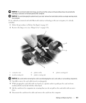
Keyboard CAUTION: Before performing the following procedures, follow the safety instructions in "Before You Begin" on page 115. 1 2 1 hinge cover 2 keyboard 2 Remove the hinge cover (see "Hinge Cover" on the computer. 1 Follow the instructions in your Product Information Guide. Adding and Replacing Parts 119 NOTICE: To avoid electrostatic discharge, ground yourself by using a wrist grounding strap or by periodically touching an unpainted metal surface (such as the back panel) on page 118).
Keyboard CAUTION: Before performing the following procedures, follow the safety instructions in "Before You Begin" on page 115. 1 2 1 hinge cover 2 keyboard 2 Remove the hinge cover (see "Hinge Cover" on the computer. 1 Follow the instructions in your Product Information Guide. Adding and Replacing Parts 119 NOTICE: To avoid electrostatic discharge, ground yourself by using a wrist grounding strap or by periodically touching an unpainted metal surface (such as the back panel) on page 118).

User's Guide
Page 120
...-consuming to disconnect the keyboard cable connector from the keyboard connector on the keyboard are completely in your Product Information Guide. 120 Adding and Replacing Parts 1 2 3 4 5 6 1 screws (3) 4 pull-tab 2 keyboard tabs (5) 3 palm rest 5 keyboard-cable locking arm 6 keyboard cable connector NOTICE: The keycaps on the system board...
...-consuming to disconnect the keyboard cable connector from the keyboard connector on the keyboard are completely in your Product Information Guide. 120 Adding and Replacing Parts 1 2 3 4 5 6 1 screws (3) 4 pull-tab 2 keyboard tabs (5) 3 palm rest 5 keyboard-cable locking arm 6 keyboard cable connector NOTICE: The keycaps on the system board...
User's Guide
Page 121
... underneath the metal tab with the other hand. 5 Lift the card from the compartment, ensuring that you begin working inside the computer. Adding and Replacing Parts 121
... underneath the metal tab with the other hand. 5 Lift the card from the compartment, ensuring that you begin working inside the computer. Adding and Replacing Parts 121

User's Guide
Page 122
... system board, you must remove the main battery before you begin working inside the computer. 1 Follow the procedures in your computer. 122 Adding and Replacing Parts
... system board, you must remove the main battery before you begin working inside the computer. 1 Follow the procedures in your computer. 122 Adding and Replacing Parts
User's Guide
Page 123
... computer has two user-accessible SODIMM sockets, one memory module, install the memory module in the connector labeled "DIMMA." Adding and Replacing Parts 123 b Remove the module from the bottom of the computer (DIMM B). Otherwise, your fingertips to carefully spread apart the securing clips ...a memory module, ground yourself and remove the existing module: a Use your computer may have, even if you purchased the new modules from Dell are covered under your computer has only one accessed from beneath the keyboard (DIMM A), and the other accessed from the connector. To add ...
... computer has two user-accessible SODIMM sockets, one memory module, install the memory module in the connector labeled "DIMMA." Adding and Replacing Parts 123 b Remove the module from the bottom of the computer (DIMM B). Otherwise, your fingertips to carefully spread apart the securing clips ...a memory module, ground yourself and remove the existing module: a Use your computer may have, even if you purchased the new modules from Dell are covered under your computer has only one accessed from beneath the keyboard (DIMM A), and the other accessed from the connector. To add ...

User's Guide
Page 124
... 115. 2 Turn the computer bottom-side up, loosen the captive screw in the memory module cover, and then remove the cover. 124 Adding and Replacing Parts
... 115. 2 Turn the computer bottom-side up, loosen the captive screw in the memory module cover, and then remove the cover. 124 Adding and Replacing Parts

User's Guide
Page 125
b Remove the module from the connector. 1 2 Adding and Replacing Parts 125 1 2 1 memory module cover 2 captive screw NOTICE: To prevent damage to the memory module connector, do not use tools to spread the memory-module securing clips. 3 If you are replacing a memory module, ground yourself and remove the existing module: a Use your fingertips to carefully spread apart the securing clips on each end of the memory module connector until the module pops up.
b Remove the module from the connector. 1 2 Adding and Replacing Parts 125 1 2 1 memory module cover 2 captive screw NOTICE: To prevent damage to the memory module connector, do not use tools to spread the memory-module securing clips. 3 If you are replacing a memory module, ground yourself and remove the existing module: a Use your fingertips to carefully spread apart the securing clips on each end of the memory module connector until the module pops up.

User's Guide
Page 126
... the tab in the computer, click Start→ Help and Support, and then click Computer Information. 8 Replace the memory module cover. 126 Adding and Replacing Parts No error message indicates this failure.
... the tab in the computer, click Start→ Help and Support, and then click Computer Information. 8 Replace the memory module cover. 126 Adding and Replacing Parts No error message indicates this failure.

User's Guide
Page 127
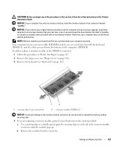
CAUTION: Before you ordered a WLAN card with your computer, the card is already installed. Wireless Local Area Network (WLAN) Card If you begin any of the procedures in this section, follow the safety instructions in the Product Information Guide. 1 Follow the procedures in "Before You Begin" on page 115. 2 Remove the hinge cover (see "Hinge Cover" on page 118). 3 Remove the keyboard (see "Keyboard" on page 119). Adding and Replacing Parts 127
CAUTION: Before you ordered a WLAN card with your computer, the card is already installed. Wireless Local Area Network (WLAN) Card If you begin any of the procedures in this section, follow the safety instructions in the Product Information Guide. 1 Follow the procedures in "Before You Begin" on page 115. 2 Remove the hinge cover (see "Hinge Cover" on page 118). 3 Remove the keyboard (see "Keyboard" on page 119). Adding and Replacing Parts 127

User's Guide
Page 128
... the metal securing tabs until the card pops up slightly. c Slide and lift the WLAN card out of card you ordered. 128 Adding and Replacing Parts NOTE: The WLAN card may have two or three connectors, depending on the type of its connector. If you feel resistance, check the connectors and...
... the metal securing tabs until the card pops up slightly. c Slide and lift the WLAN card out of card you ordered. 128 Adding and Replacing Parts NOTE: The WLAN card may have two or three connectors, depending on the type of its connector. If you feel resistance, check the connectors and...


