
Owners Manual
Page 4
Keyboard lattice and Keyboard...25 Removing keyboard lattice...25 Installing keyboard lattice...26 Removing the keyboard...26 Installing the keyboard...29 Heat sink ...29 Removing the heat sink ...29 Installing the heat sink ...30 System fan...30 Removing the system fan...30 Installing the system ...
Keyboard lattice and Keyboard...25 Removing keyboard lattice...25 Installing keyboard lattice...26 Removing the keyboard...26 Installing the keyboard...29 Heat sink ...29 Removing the heat sink ...29 Installing the heat sink ...30 System fan...30 Removing the system fan...30 Installing the system ...

Owners Manual
Page 5
... Audio specifications...60 Video specification...61 Integrated...61 Discrete...61 Camera option ...61 Ports and Connectors ...62 Contacted smart card specifications...62 Display specification...62 Keyboard specifications ...64 Touch pad specifications...65 Battery specifications...65 AC Adapter specifications...66 System dimensions...67 Operating Conditions...67 4 Technology and components...69 Power adapter...
... Audio specifications...60 Video specification...61 Integrated...61 Discrete...61 Camera option ...61 Ports and Connectors ...62 Contacted smart card specifications...62 Display specification...62 Keyboard specifications ...64 Touch pad specifications...65 Battery specifications...65 AC Adapter specifications...66 System dimensions...67 Operating Conditions...67 4 Technology and components...69 Power adapter...

Owners Manual
Page 10
optional • Memory modules • Keyboard lattice and Keyboard • Heat sink • System fan • Power connector port • Chassis frame • SmartCard module • Speaker • System board • Display hinge cover &#...
optional • Memory modules • Keyboard lattice and Keyboard • Heat sink • System fan • Power connector port • Chassis frame • SmartCard module • Speaker • System board • Display hinge cover &#...

Owners Manual
Page 11
Screw size list Table 1. Latitude 5490 screw size list Component Base cover M2x3 (Thin head) Battery Heatsink 4 WLAN 1 SSD card 1 Keyboard Display assembly Display panel 4 Power connector port 2 Palmrest 2 LED board System board 4 Type-C USB bracket Display hinge cover 2 Display hinge Hard drive Chassis frame 5 Touchpad ...
Screw size list Table 1. Latitude 5490 screw size list Component Base cover M2x3 (Thin head) Battery Heatsink 4 WLAN 1 SSD card 1 Keyboard Display assembly Display panel 4 Power connector port 2 Palmrest 2 LED board System board 4 Type-C USB bracket Display hinge cover 2 Display hinge Hard drive Chassis frame 5 Touchpad ...

Owners Manual
Page 25
NOTE: Gently pull or lift keyboard lattice in Before working inside your computer. Then, press the module until the contacts are fully seated into the memory connector at a 30 degree angle ...until the clips secure the memory module. 2 Install the : a battery b base cover 3 Follow the procedure in After working inside your computer. 2 Pry the keyboard lattice from one of the recess points [1] and lift the lattice from the system [2]. Installing the memory module 1 Insert the memory module into the slot...
NOTE: Gently pull or lift keyboard lattice in Before working inside your computer. Then, press the module until the contacts are fully seated into the memory connector at a 30 degree angle ...until the clips secure the memory module. 2 Install the : a battery b base cover 3 Follow the procedure in After working inside your computer. 2 Pry the keyboard lattice from one of the recess points [1] and lift the lattice from the system [2]. Installing the memory module 1 Insert the memory module into the slot...

Owners Manual
Page 26
... press along the edges and in between the rows of cables to disconnect is based on the keyboard type. 26 Removing and installing components b Lift the latch and disconnect the keyboard backlight cables from the connector on the system. NOTE: Number of keys until the lattice clicks in place. 2 Follow the procedure...
... press along the edges and in between the rows of cables to disconnect is based on the keyboard type. 26 Removing and installing components b Lift the latch and disconnect the keyboard backlight cables from the connector on the system. NOTE: Number of keys until the lattice clicks in place. 2 Follow the procedure...
Owners Manual
Page 27
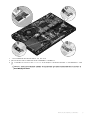
WARNING: Gently pull the keyboard cable and the keyboard back light cables routed beneath the chassis frame to the system [1]. e Flip the keyboard from the bottom and lift it from the system along with the keyboard cable and the keyboard back light cable [2]. d Remove the five (M2x2.5) screws that secure the keyboard to avoid damaging the cables. Removing and installing components 27 c Turn over the system and open the laptop in front view mode.
WARNING: Gently pull the keyboard cable and the keyboard back light cables routed beneath the chassis frame to the system [1]. e Flip the keyboard from the bottom and lift it from the system along with the keyboard cable and the keyboard back light cable [2]. d Remove the five (M2x2.5) screws that secure the keyboard to avoid damaging the cables. Removing and installing components 27 c Turn over the system and open the laptop in front view mode.

Owners Manual
Page 29
...Follow the procedure in Before working inside your computer. Removing and installing components 29 Installing the keyboard 1 Hold the keyboard and route the keyboard cable and the keyboard backlight cables through the opening in the frame before connecting them to the connector in sequential ... on the system. 3 Replace the five (M2x2.5) screws to secure the keyboard to the system. 4 Turn the system over and connect the keyboard cable and the keyboard backlight cable to system board. 5 Install the: a keyboard lattice b battery c base cover 6 Follow the procedure in After working inside...
...Follow the procedure in Before working inside your computer. Removing and installing components 29 Installing the keyboard 1 Hold the keyboard and route the keyboard cable and the keyboard backlight cables through the opening in the frame before connecting them to the connector in sequential ... on the system. 3 Replace the five (M2x2.5) screws to secure the keyboard to the system. 4 Turn the system over and connect the keyboard cable and the keyboard backlight cable to system board. 5 Install the: a keyboard lattice b battery c base cover 6 Follow the procedure in After working inside...

Owners Manual
Page 33
...: M2x5 8ea and M2x3 5ea 3 To release the chassis frame: a Unroute the WLAN cables from their connectors [2,3,4,5] on the keyboard type. b Lift the latch and disconnect the keyboard backlight cable and the keyboard cable from the routing channels [1]. NOTE: There may be more than one cable to disconnect based on the system. Removing...
...: M2x5 8ea and M2x3 5ea 3 To release the chassis frame: a Unroute the WLAN cables from their connectors [2,3,4,5] on the keyboard type. b Lift the latch and disconnect the keyboard backlight cable and the keyboard cable from the routing channels [1]. NOTE: There may be more than one cable to disconnect based on the system. Removing...

Owners Manual
Page 34
... the system. 2 Replace the five (M2x3) screws and eight (M2x5) screws to secure the chassis frame to the system. 3 Connect the keyboard cable and the keyboard backlight cable to connect based on keyboard types. 4 Route the WLAN cables through the routing channels. 5 Install the: a WWAN card (optional) b WLAN card c SSD frame d SSD card...
... the system. 2 Replace the five (M2x3) screws and eight (M2x5) screws to secure the chassis frame to the system. 3 Connect the keyboard cable and the keyboard backlight cable to connect based on keyboard types. 4 Route the WLAN cables through the routing channels. 5 Install the: a WWAN card (optional) b WLAN card c SSD frame d SSD card...

Owners Manual
Page 37
Speaker Removing the speaker 1 Follow the procedure in Before working inside your computer. 2 Remove the: a base cover b battery c memory module d hard drive e SSD card f SSD frame g WLAN card h WWAN card (optional) i keyboard lattice j keyboard k chassis frame l system board 3 To remove the speakers: a Release the speaker cable through the routing channels [1]. Removing and installing components 37 b Lift the speaker away from the computer [2].
Speaker Removing the speaker 1 Follow the procedure in Before working inside your computer. 2 Remove the: a base cover b battery c memory module d hard drive e SSD card f SSD frame g WLAN card h WWAN card (optional) i keyboard lattice j keyboard k chassis frame l system board 3 To remove the speakers: a Release the speaker cable through the routing channels [1]. Removing and installing components 37 b Lift the speaker away from the computer [2].

Owners Manual
Page 38
...it with the nodes on the chassis. 2 Route the speaker cable through the routing channels. 3 Install the: a system board b chassis frame c keyboard d keyboard lattice e WLAN card f SSD frame g SSD card h hard drive i memory module j battery k base cover l SIM card 4 Follow the ... Remove the: a SIM card b base cover c battery d memory module e hard drive f SSD card g SSD frame h WLAN card i WWAN card (optional) j keyboard lattice k keyboard l heat sink m chassis frame n system fan 3 Disconnect the following cables from the system board: a Touchpad cable [1] b USH cable [2] c LED board cable [3] ...
...it with the nodes on the chassis. 2 Route the speaker cable through the routing channels. 3 Install the: a system board b chassis frame c keyboard d keyboard lattice e WLAN card f SSD frame g SSD card h hard drive i memory module j battery k base cover l SIM card 4 Follow the ... Remove the: a SIM card b base cover c battery d memory module e hard drive f SSD card g SSD frame h WLAN card i WWAN card (optional) j keyboard lattice k keyboard l heat sink m chassis frame n system fan 3 Disconnect the following cables from the system board: a Touchpad cable [1] b USH cable [2] c LED board cable [3] ...

Owners Manual
Page 41
... mode. 10 Connect the following cables: a Touchpad cable b LED board cable c USH board cable d speaker cable 11 Install the: a system fan b chassis frame c heat sink d keyboard e keyboard lattice f WWAN card (optional) g WLAN card Removing and installing components 41
... mode. 10 Connect the following cables: a Touchpad cable b LED board cable c USH board cable d speaker cable 11 Install the: a system fan b chassis frame c heat sink d keyboard e keyboard lattice f WWAN card (optional) g WLAN card Removing and installing components 41

Owners Manual
Page 57
Installing palm rest 1 Place the palm rest on a flat surface. 2 Install the: a display assembly b display hinge cover c system board d system fan e chassis frame Removing and installing components 57 a SIM card b base cover c battery d memory module e hard drive f SSD card g SSD frame h WLAN card i WWAN card (optional) j keyboard lattice k keyboard l heat sink m chassis frame n system fan o system board p display hinge cover q display assembly 3 The palm rest is the remaining component after removing all the components.
Installing palm rest 1 Place the palm rest on a flat surface. 2 Install the: a display assembly b display hinge cover c system board d system fan e chassis frame Removing and installing components 57 a SIM card b base cover c battery d memory module e hard drive f SSD card g SSD frame h WLAN card i WWAN card (optional) j keyboard lattice k keyboard l heat sink m chassis frame n system fan o system board p display hinge cover q display assembly 3 The palm rest is the remaining component after removing all the components.

Owners Manual
Page 58
f heat sink assembly g keyboard h keyboard lattice i WWAN card (optional) j WLAN card k SSD frame l SSD card m hard drive n memory module o battery p base cover q SIM card 3 Follow the procedure in After working inside your computer. 58 Removing and installing components
f heat sink assembly g keyboard h keyboard lattice i WWAN card (optional) j WLAN card k SSD frame l SSD card m hard drive n memory module o battery p base cover q SIM card 3 Follow the procedure in After working inside your computer. 58 Removing and installing components

Owners Manual
Page 59
... • Storage specifications • Audio specifications • Video specification • Camera option • Ports and Connectors • Contacted smart card specifications • Display specification • Keyboard specifications • Touch pad specifications • Battery specifications • AC Adapter specifications • System dimensions • Operating Conditions Processor > Settings > System > About. Table 2. Processor specifications...
... • Storage specifications • Audio specifications • Video specification • Camera option • Ports and Connectors • Contacted smart card specifications • Display specification • Keyboard specifications • Touch pad specifications • Battery specifications • AC Adapter specifications • System dimensions • Operating Conditions Processor > Settings > System > About. Table 2. Processor specifications...

Owners Manual
Page 61
... HD fixed focus Optional CMOS sensor technology Technical specifications 61 Table 5. Feature Specification • Noise reducing array microphones • Volume control buttons, supports hot-key keyboard button External interface Stereo headset/mic combo Speakers Two Volume controls Hot keys Video specification Integrated Feature Type UMA controller Specification Integrated on system board...
... HD fixed focus Optional CMOS sensor technology Technical specifications 61 Table 5. Feature Specification • Noise reducing array microphones • Volume control buttons, supports hot-key keyboard button External interface Stereo headset/mic combo Speakers Two Volume controls Hot keys Video specification Integrated Feature Type UMA controller Specification Integrated on system board...

Owners Manual
Page 62
... 4.0 Memory card reader Yes (optional) Yes (optional) Yes (optional) Universal Audio JAck High Quality Speakers Noise reducing array microphones Volume control buttons, supports hot-key keyboard button DisplayPort over USB Type-C. Ports and Connectors USB Video Network Modem Expansion Smart Card Reader Touch Fingerprint Reader Contactless card reader Audio Docking Three...
... 4.0 Memory card reader Yes (optional) Yes (optional) Yes (optional) Universal Audio JAck High Quality Speakers Noise reducing array microphones Volume control buttons, supports hot-key keyboard button DisplayPort over USB Type-C. Ports and Connectors USB Video Network Modem Expansion Smart Card Reader Touch Fingerprint Reader Contactless card reader Audio Docking Three...

Owners Manual
Page 64
..., press Shift and the desired key. Brightness down Brightness up Sleep Wireless on them. To perform secondary functions, press Fn and the desired key. Table 8. Keyboard hot key definitions Fn Key Combination Fn+ESC Fn+ F1 Fn + F2 Fn + F3 Fn + F4 Fn + F5 Fn + F6 Fn + F8 Fn + F9... on/off 64 Technical specifications These keys can be used to type alternate characters or to the optional dual point backlit keyboard. Keyboard specifications Feature Number of keys Specification • United States: 82 keys • United Kingdom: 83 keys • Japan: 86 keys • Brazil: 84 keys...
..., press Shift and the desired key. Brightness down Brightness up Sleep Wireless on them. To perform secondary functions, press Fn and the desired key. Table 8. Keyboard hot key definitions Fn Key Combination Fn+ESC Fn+ F1 Fn + F2 Fn + F3 Fn + F4 Fn + F5 Fn + F6 Fn + F8 Fn + F9... on/off 64 Technical specifications These keys can be used to type alternate characters or to the optional dual point backlit keyboard. Keyboard specifications Feature Number of keys Specification • United States: 82 keys • United Kingdom: 83 keys • Japan: 86 keys • Brazil: 84 keys...

Owners Manual
Page 72
... Channel - Adds high-speed networking to an HDMI link, allowing users to optimize picture settings based on the bottom of the system or under the keyboard, as a digital TV (DTV). Real-time signaling of their IP-enabled devices without a separate Ethernet cable • Audio Return Channel - Thickness difference Curved edge DDR4...
... Channel - Adds high-speed networking to an HDMI link, allowing users to optimize picture settings based on the bottom of the system or under the keyboard, as a digital TV (DTV). Real-time signaling of their IP-enabled devices without a separate Ethernet cable • Audio Return Channel - Thickness difference Curved edge DDR4...


