Owner's Manual (PDF)
Page 4
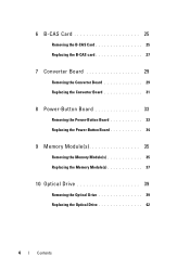
6 B-CAS Card 25 Removing the B-CAS Card 25 Replacing the B-CAS card 27 7 Converter Board 29 Removing the Converter Board 29 Replacing the Converter Board 31 8 Power-Button Board 33 Removing the Power-Button Board 33 Replacing the Power-Button Board 34 9 Memory Module(s 35 Removing the Memory Module(s 35 Replacing the Memory Module(s 37 10 Optical Drive 39 Removing the Optical Drive 39 Replacing the Optical Drive 42 4 Contents
6 B-CAS Card 25 Removing the B-CAS Card 25 Replacing the B-CAS card 27 7 Converter Board 29 Removing the Converter Board 29 Replacing the Converter Board 31 8 Power-Button Board 33 Removing the Power-Button Board 33 Replacing the Power-Button Board 34 9 Memory Module(s 35 Removing the Memory Module(s 35 Replacing the Memory Module(s 37 10 Optical Drive 39 Removing the Optical Drive 39 Replacing the Optical Drive 42 4 Contents
Owner's Manual (PDF)
Page 16
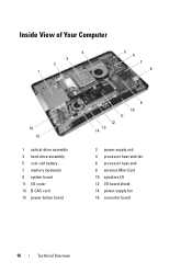
Inside View of Your Computer 4 3 2 1 5 6 7 8 16 15 1 optical-drive assembly 3 hard-drive assembly 5 coin-cell battery 7 memory module(s) 9 system board 11 I/O cover 13 B-CAS card 15 power-button board 11 12 13 14 9 10 2 power-supply unit 4 processor heat-sink fan 6 processor heat-sink 8 wireless Mini-Card 10 speakers (2) 12 I/O board shield 14 power-supply fan 16 converter board 16 Technical Overview
Inside View of Your Computer 4 3 2 1 5 6 7 8 16 15 1 optical-drive assembly 3 hard-drive assembly 5 coin-cell battery 7 memory module(s) 9 system board 11 I/O cover 13 B-CAS card 15 power-button board 11 12 13 14 9 10 2 power-supply unit 4 processor heat-sink fan 6 processor heat-sink 8 wireless Mini-Card 10 speakers (2) 12 I/O board shield 14 power-supply fan 16 converter board 16 Technical Overview
Owner's Manual (PDF)
Page 18
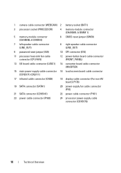
1 camera cable connector (WEBCAM) 2 battery socket (BAT1) 3 processor socket (PROCESSOR) 4 memory-module connector (CHANNEL A DIMM 1) 5 memory-module connector (CHANNEL A DIMM 0) 6 CMOS reset jumper (SW50) 7 left speaker cable connector (LINE_OUT) 8 right speaker cable connector (LINE_OUT) 9 password reset jumper (E49) 10 SPI connector (...
1 camera cable connector (WEBCAM) 2 battery socket (BAT1) 3 processor socket (PROCESSOR) 4 memory-module connector (CHANNEL A DIMM 1) 5 memory-module connector (CHANNEL A DIMM 0) 6 CMOS reset jumper (SW50) 7 left speaker cable connector (LINE_OUT) 8 right speaker cable connector (LINE_OUT) 9 password reset jumper (E49) 10 SPI connector (...
Owner's Manual (PDF)
Page 35
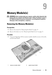
For additional safety best practices information, see the Regulatory Compliance Homepage at dell.com/regulatory_compliance. Removing the Memory Module(s) Prerequisites 1 Remove the stand. Procedure 1 Using your computer and follow the steps in "Before You Begin" on page 11. See "Removing the Back Cover" ...on page 19. 2 Remove the back cover. See "Removing the Stand" on page 23. Memory Module(s) WARNING: Before working inside your computer, read the safety information that shipped with your fingertips, lift the...
For additional safety best practices information, see the Regulatory Compliance Homepage at dell.com/regulatory_compliance. Removing the Memory Module(s) Prerequisites 1 Remove the stand. Procedure 1 Using your computer and follow the steps in "Before You Begin" on page 11. See "Removing the Back Cover" ...on page 19. 2 Remove the back cover. See "Removing the Stand" on page 23. Memory Module(s) WARNING: Before working inside your computer, read the safety information that shipped with your fingertips, lift the...

Owner's Manual (PDF)
Page 36
2 Use your fingertips to carefully spread apart the securing clips on each end of the memory-module connector until the memory module pops up. 3 Remove the memory module from the memory-module connector. 2 1 1 securing clips (2) 3 memory module 3 2 memory-module connector 36 Memory Module(s)
2 Use your fingertips to carefully spread apart the securing clips on each end of the memory-module connector until the memory module pops up. 3 Remove the memory module from the memory-module connector. 2 1 1 securing clips (2) 3 memory module 3 2 memory-module connector 36 Memory Module(s)
Owner's Manual (PDF)
Page 37
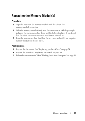
... 1 Replace the back cover. See "Replacing the Back Cover" on the memory-module connector. 2 Slide the memory module firmly into the connector at a 45-degree angle, and press the memory module down until it . 3 Place the memory-module shield on page 13. If you do not hear the click, remove... the memory module and reinstall it clicks into place. Memory Module(s) 37 See "Replacing the Stand" on page 21. 3...
... 1 Replace the back cover. See "Replacing the Back Cover" on the memory-module connector. 2 Slide the memory module firmly into the connector at a 45-degree angle, and press the memory module down until it . 3 Place the memory-module shield on page 13. If you do not hear the click, remove... the memory module and reinstall it clicks into place. Memory Module(s) 37 See "Replacing the Stand" on page 21. 3...

Owner's Manual (PDF)
Page 38
38 Memory Module(s)
38 Memory Module(s)
Owner's Manual (PDF)
Page 113
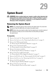
.... Removing the System Board NOTE: Your computer's Service Tag is stored in the BIOS after you replace the system board. See "Removing the Memory Module(s)" on page 11. See "Removing the I /O board shield. For additional safety best practices information, see the Regulatory Compliance Homepage at... dell.com/regulatory_compliance. You must enter the Service Tag in the system board. See "Removing the Power-Supply Fan Bracket" on page 85. 10 ...
.... Removing the System Board NOTE: Your computer's Service Tag is stored in the BIOS after you replace the system board. See "Removing the Memory Module(s)" on page 11. See "Removing the I /O board shield. For additional safety best practices information, see the Regulatory Compliance Homepage at... dell.com/regulatory_compliance. You must enter the Service Tag in the system board. See "Removing the Power-Supply Fan Bracket" on page 85. 10 ...
Owner's Manual (PDF)
Page 115
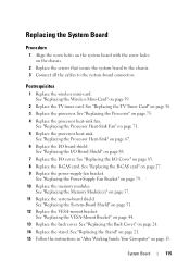
See "Replacing the Processor Heat-Sink Fan" on page 79. 10 Replace the memory modules. See "Replacing the Power-Supply Fan Bracket" on page 71. 5 Replace the processor heat-sink. See "Replacing the VESA-Mount Bracket" on page 27. 9 ... page 75. 4 Replace the processor heat-sink fan. See "Replacing the Processor" on page 83. 8 Replace the B-CAS card. System Board 115 See "Replacing the Memory Module(s)" on page 67. 6 Replace the I /O cover.
See "Replacing the Processor Heat-Sink Fan" on page 79. 10 Replace the memory modules. See "Replacing the Power-Supply Fan Bracket" on page 71. 5 Replace the processor heat-sink. See "Replacing the VESA-Mount Bracket" on page 27. 9 ... page 75. 4 Replace the processor heat-sink fan. See "Replacing the Processor" on page 83. 8 Replace the B-CAS card. System Board 115 See "Replacing the Memory Module(s)" on page 67. 6 Replace the I /O cover.
Owner's Manual (PDF)
Page 117
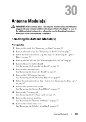
... Begin" on page 49. 10 Remove the TV tuner card. Antenna Module(s) 117 See "Removing the Power-Button Board" on page 53. 11 Remove the memory modules. See "Removing the TV Tuner Card" on page 33. 6 Remove the converter board. For additional safety best practices information, see the Regulatory Compliance Homepage...
... Begin" on page 49. 10 Remove the TV tuner card. Antenna Module(s) 117 See "Removing the Power-Button Board" on page 53. 11 Remove the memory modules. See "Removing the TV Tuner Card" on page 33. 6 Remove the converter board. For additional safety best practices information, see the Regulatory Compliance Homepage...
Owner's Manual (PDF)
Page 120
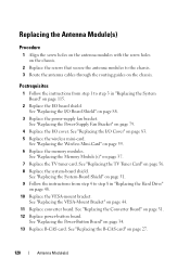
... Replace the screws that secure the antenna modules to the chassis. 3 Route the antenna cables through the routing guides on page 59. 6 Replace the memory modules. Postrequisites 1 Follow the instructions from step 4 to step 3 in "Replacing the Hard Drive" on page 48. 10 Replace the VESA-mount ...on page 31. 12 Replace power-button board. See "Replacing the Converter Board" on page 56. 8 Replace the system-board shield. See "Replacing the Memory Module(s)" on page 88. 3 Replace the power-supply fan bracket. See "Replacing the I /O board shield. See "Replacing the B-CAS card" on ...
... Replace the screws that secure the antenna modules to the chassis. 3 Route the antenna cables through the routing guides on page 59. 6 Replace the memory modules. Postrequisites 1 Follow the instructions from step 4 to step 3 in "Replacing the Hard Drive" on page 48. 10 Replace the VESA-mount ...on page 31. 12 Replace power-button board. See "Replacing the Converter Board" on page 56. 8 Replace the system-board shield. See "Replacing the Memory Module(s)" on page 88. 3 Replace the power-supply fan bracket. See "Replacing the I /O board shield. See "Replacing the B-CAS card" on ...
Owner's Manual (PDF)
Page 123
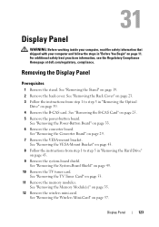
... Remove the converter board. See "Removing the Power-Button Board" on page 25. 5 Remove the power-button board. See "Removing the Memory Module(s)" on page 11. Display Panel WARNING: Before working inside your computer, read the safety information that shipped with your computer and follow ...Converter Board" on page 49. 10 Remove the TV tuner card. For additional safety best practices information, see the Regulatory Compliance Homepage at dell.com/regulatory_compliance. See "Removing the System-Board Shield" on page 29. 7 Remove the VESA-mount bracket. See "Removing the TV Tuner...
... Remove the converter board. See "Removing the Power-Button Board" on page 25. 5 Remove the power-button board. See "Removing the Memory Module(s)" on page 11. Display Panel WARNING: Before working inside your computer, read the safety information that shipped with your computer and follow ...Converter Board" on page 49. 10 Remove the TV tuner card. For additional safety best practices information, see the Regulatory Compliance Homepage at dell.com/regulatory_compliance. See "Removing the System-Board Shield" on page 29. 7 Remove the VESA-mount bracket. See "Removing the TV Tuner...
Owner's Manual (PDF)
Page 129
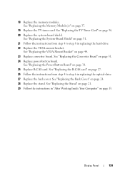
... "Replacing the Stand" on page 21. 29 Follow the instructions in replacing the optical-drive 27 Replace the back cover. 18 Replace the memory modules. See "Replacing the Memory Module(s)" on page 44. 23 Replace converter board. See "Replacing the VESA-Mount Bracket" on page 37. 19 Replace the TV tuner card...
... "Replacing the Stand" on page 21. 29 Follow the instructions in replacing the optical-drive 27 Replace the back cover. 18 Replace the memory modules. See "Replacing the Memory Module(s)" on page 44. 23 Replace converter board. See "Replacing the VESA-Mount Bracket" on page 37. 19 Replace the TV tuner card...
Owner's Manual (PDF)
Page 131
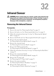
...Regulatory Compliance Homepage at dell.com/regulatory_compliance. Removing the Infrared Sensor Prerequisites 1 Remove the stand. See "Removing the Stand" on page 25. 5 Remove the power-button board. See "Removing the B-CAS Card" on page 19. 2 Remove the back cover. See "Removing the Memory Module(s)" on page... 53. 11 Remove the memory modules. See "Removing the TV Tuner Card" on page 35. 12 Remove the wireless mini-card. See "Removing the ...
...Regulatory Compliance Homepage at dell.com/regulatory_compliance. Removing the Infrared Sensor Prerequisites 1 Remove the stand. See "Removing the Stand" on page 25. 5 Remove the power-button board. See "Removing the B-CAS Card" on page 19. 2 Remove the back cover. See "Removing the Memory Module(s)" on page... 53. 11 Remove the memory modules. See "Removing the TV Tuner Card" on page 35. 12 Remove the wireless mini-card. See "Removing the ...
Owner's Manual (PDF)
Page 134
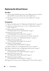
... 3 Replace the processor heat-sink fan. See "Replacing the B-CAS card" on page 37. 14 Replace the TV tuner card. See "Replacing the Memory Module(s)" on page 27. 11 Replace the power-supply fan bracket. Ensure that the infrared LED is secured under the tabs on the middle frame... Mini-Card" on page 79. 12 Replace the wireless mini-card. See "Replacing the Power-Supply Fan Bracket" on page 59. 13 Replace the memory modules. Replacing the Infrared Sensor Procedure 1 Slide the infrared LED into place. Postrequisites 1 Replace the display panel. See "Replacing the Processor Heat-Sink Fan...
... 3 Replace the processor heat-sink fan. See "Replacing the B-CAS card" on page 37. 14 Replace the TV tuner card. See "Replacing the Memory Module(s)" on page 27. 11 Replace the power-supply fan bracket. Ensure that the infrared LED is secured under the tabs on the middle frame... Mini-Card" on page 79. 12 Replace the wireless mini-card. See "Replacing the Power-Supply Fan Bracket" on page 59. 13 Replace the memory modules. Replacing the Infrared Sensor Procedure 1 Slide the infrared LED into place. Postrequisites 1 Replace the display panel. See "Replacing the Processor Heat-Sink Fan...
Owner's Manual (PDF)
Page 137
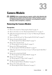
...TV tuner card. See "Removing the System-Board Shield" on page 33. 6 Remove the converter board. See "Removing the Memory Module(s)" on page 53. 11 Remove the memory modules. Camera Module 137 See "Removing the VESA-Mount Bracket" on page 43. 8 Follow the instructions from step 1 to ... the Hard Drive" on page 45. 9 Remove the system-board shield. For additional safety best practices information, see the Regulatory Compliance Homepage at dell.com/regulatory_compliance. See "Removing the B-CAS Card" on page 57. See "Removing the Stand" on page 29. 7 Remove the VESA-mount bracket...
...TV tuner card. See "Removing the System-Board Shield" on page 33. 6 Remove the converter board. See "Removing the Memory Module(s)" on page 53. 11 Remove the memory modules. Camera Module 137 See "Removing the VESA-Mount Bracket" on page 43. 8 Follow the instructions from step 1 to ... the Hard Drive" on page 45. 9 Remove the system-board shield. For additional safety best practices information, see the Regulatory Compliance Homepage at dell.com/regulatory_compliance. See "Removing the B-CAS Card" on page 57. See "Removing the Stand" on page 29. 7 Remove the VESA-mount bracket...
Owner's Manual (PDF)
Page 140
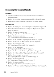
..." on page 67. 5 Replace the I /O Cover" on page 83. 10 Replace the B-CAS card. See "Replacing the Speakers" on page 59. 13 Replace the memory modules. See "Replacing the I /O board. See "Replacing the Wireless Mini-Card" on page 63. 7 Replace the power-supply unit. See "Replacing the... Memory Module(s)" on page 79. 12 Replace the wireless mini-card. Postrequisites 1 Replace the display panel. See "Replacing the I /O cover. See "Replacing the I/O Board Shield"...
..." on page 67. 5 Replace the I /O Cover" on page 83. 10 Replace the B-CAS card. See "Replacing the Speakers" on page 59. 13 Replace the memory modules. See "Replacing the I /O board. See "Replacing the Wireless Mini-Card" on page 63. 7 Replace the power-supply unit. See "Replacing the... Memory Module(s)" on page 79. 12 Replace the wireless mini-card. Postrequisites 1 Replace the display panel. See "Replacing the I /O cover. See "Replacing the I/O Board Shield"...
Owner's Manual (PDF)
Page 145
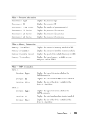
... Displays the amount of memory installed in MB Memory Available Displays the amount of installed memory available Memory Running Speed Displays the speed of the installed memory in MHz Memory Technology Displays the type of the device installed, if the device is a hard drive Displays the type of device... installed on the SATA2 connector Displays the serial number of the device installed Displays the size of memory installed on the SATA1 connector Displays the serial number of the device installed Displays the size of the device installed, if the device...
... Displays the amount of memory installed in MB Memory Available Displays the amount of installed memory available Memory Running Speed Displays the speed of the installed memory in MHz Memory Technology Displays the type of the device installed, if the device is a hard drive Displays the type of device... installed on the SATA2 connector Displays the serial number of the device installed Displays the size of memory installed on the SATA1 connector Displays the serial number of the device installed Displays the size of the device installed, if the device...
Owner's Manual (PDF)
Page 150
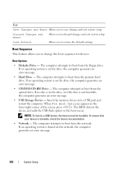
The computer attempts to boot from the floppy drive. Insert the memory device into a USB port and restart the computer. The computer attempts to boot from the network. When F12 Boot Options appears in the drive, or ...
The computer attempts to boot from the floppy drive. Insert the memory device into a USB port and restart the computer. The computer attempts to boot from the network. When F12 Boot Options appears in the drive, or ...
Owner's Manual (PDF)
Page 151
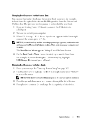
Changing Boot Sequence for example, to boot from the optical drive to run Dell Diagnostics from the Drivers and Utilities disc. The previous boot sequence is restored at the next boot. 1 If you are booting to a USB memory key, highlight USB Storage Device and press . NOTE: If you wait too long and the...
Changing Boot Sequence for example, to boot from the optical drive to run Dell Diagnostics from the Drivers and Utilities disc. The previous boot sequence is restored at the next boot. 1 If you are booting to a USB memory key, highlight USB Storage Device and press . NOTE: If you wait too long and the...


