Setup Guide
Page 5
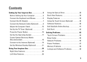
Contents Setting Up Your Inspiron One 5 Before Setting Up Your Computer 5 Connect the Keyboard and Mouse 6 Connect the AC Adapter 7 Connect the Network Cable (Optional 8 Adjust the Computer Stand 10 Set Up the TV Tuner (Optional 11 Press the Power Button 16 Set Up the Operating System...Display (Optional 21 Using Your Inspiron One 24 Right View Features 24 Left View Features 26 Using the Optical Drive 28 Back View Features 30 Display Features 34 Using the Touch Screen (Optional 36 Software Features 40 Dell DataSafe Online Backup 41 Dell Dock 42 Solving Problems 43 ...
Contents Setting Up Your Inspiron One 5 Before Setting Up Your Computer 5 Connect the Keyboard and Mouse 6 Connect the AC Adapter 7 Connect the Network Cable (Optional 8 Adjust the Computer Stand 10 Set Up the TV Tuner (Optional 11 Press the Power Button 16 Set Up the Operating System...Display (Optional 21 Using Your Inspiron One 24 Right View Features 24 Left View Features 26 Using the Optical Drive 28 Back View Features 30 Display Features 34 Using the Touch Screen (Optional 36 Software Features 40 Dell DataSafe Online Backup 41 Dell Dock 42 Solving Problems 43 ...
Setup Guide
Page 12
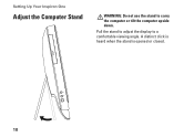
Pull the stand to adjust the display to carry the computer or tilt the computer upside down. A distinct click is heard when the stand is opened or closed. 10 Setting Up Your Inspiron One Adjust the Computer Stand WARNING: Do not use the stand to a comfortable viewing angle.
Pull the stand to adjust the display to carry the computer or tilt the computer upside down. A distinct click is heard when the stand is opened or closed. 10 Setting Up Your Inspiron One Adjust the Computer Stand WARNING: Do not use the stand to a comfortable viewing angle.
Setup Guide
Page 27
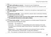
...avoid loss of data, never turn off the computer, move the computer, or adjust the stand while the hard drive activity light is not receiving power. 25 The computer is in sleep...standby mode or there might be an issue with audio programs. 7 Hard drive activity light - Contact Dell (see "Contacting Dell" on page 75) for assistance. • Off - The computer is in /Microphone connector - NOTE... the Power-on when the computer reads or writes data. Using Your Inspiron One 5 Audio-out/Headphone connector - Connects to a microphone or inputs signal for use the line-out connector ...
...avoid loss of data, never turn off the computer, move the computer, or adjust the stand while the hard drive activity light is not receiving power. 25 The computer is in sleep...standby mode or there might be an issue with audio programs. 7 Hard drive activity light - Contact Dell (see "Contacting Dell" on page 75) for assistance. • Off - The computer is in /Microphone connector - NOTE... the Power-on when the computer reads or writes data. Using Your Inspiron One 5 Audio-out/Headphone connector - Connects to a microphone or inputs signal for use the line-out connector ...

Setup Guide
Page 29
..., VGA, or HDMI). 7 Computer stand - Press to increase the brightness level of the display. 6 Video input source button (optional) - For more information, see "Using the Optical Drive" on page 28. 2 Optical drive light - Opens the optical drive tray when pressed. 4 Brightness increase button (optional) - Using Your Inspiron One 1 Optical drive - Plays or records...
..., VGA, or HDMI). 7 Computer stand - Press to increase the brightness level of the display. 6 Video input source button (optional) - For more information, see "Using the Optical Drive" on page 28. 2 Optical drive light - Opens the optical drive tray when pressed. 4 Brightness increase button (optional) - Using Your Inspiron One 1 Optical drive - Plays or records...
Service Manual
Page 1
...: A CAUTION indicates either the entities claiming the marks and names or their products. Dell™ Inspiron™ One 2305/2310 Service Manual Technical Overview Before You Begin Back Cover Hard Drive Optical Drive Converter Card Touch Screen Control Card (Optional) Front Stand Audio Video Board Shield Audio Video Board Audio Video Board Cable Audio Video...
...: A CAUTION indicates either the entities claiming the marks and names or their products. Dell™ Inspiron™ One 2305/2310 Service Manual Technical Overview Before You Begin Back Cover Hard Drive Optical Drive Converter Card Touch Screen Control Card (Optional) Front Stand Audio Video Board Shield Audio Video Board Audio Video Board Cable Audio Video...
Service Manual
Page 2
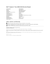
... the connectors on the AV board. 6. Replace the back cover (see the Regulatory Compliance Homepage at www.dell.com/regulatory_compliance. Back to Contents Page Audio Video Board Dell™ Inspiron™ One 2305/2310 Service Manual Removing the Audio Video (AV) Board Replacing the Audio Video (AV) Board WARNING: Before... that secure the AV board to servicing that shipped with the screw holes on the chassis. 3. Follow the instructions in Replacing the Front Stand. 7. Align the screw holes on the AV board. 5. Replace the five screws that secure the AV board to the connectors on the...
... the connectors on the AV board. 6. Replace the back cover (see the Regulatory Compliance Homepage at www.dell.com/regulatory_compliance. Back to Contents Page Audio Video Board Dell™ Inspiron™ One 2305/2310 Service Manual Removing the Audio Video (AV) Board Replacing the Audio Video (AV) Board WARNING: Before... that secure the AV board to servicing that shipped with the screw holes on the chassis. 3. Follow the instructions in Replacing the Front Stand. 7. Align the screw holes on the AV board. 5. Replace the five screws that secure the AV board to the connectors on the...
Service Manual
Page 4
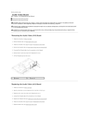
...Stand. 4. Follow the instructions from the chassis. 1 AV-board shield 2 screws (3) Replacing the Audio Video (AV) Board Shield 1. Align the screw holes on your computer). Failure to do so may result in Before You Begin. 2. Back to Contents Page Audio Video Board Shield Dell™ Inspiron™ One 2305... the instructions in damage to step 5 in Replacing the Front Stand. 5. Follow the instructions in Before You Begin. 2. Remove the back cover (see the Regulatory Compliance Homepage at www.dell.com/regulatory_compliance. Replace the back cover (see Replacing the Back ...
...Stand. 4. Follow the instructions from the chassis. 1 AV-board shield 2 screws (3) Replacing the Audio Video (AV) Board Shield 1. Align the screw holes on your computer). Failure to do so may result in Before You Begin. 2. Back to Contents Page Audio Video Board Shield Dell™ Inspiron™ One 2305... the instructions in damage to step 5 in Replacing the Front Stand. 5. Follow the instructions in Before You Begin. 2. Remove the back cover (see the Regulatory Compliance Homepage at www.dell.com/regulatory_compliance. Replace the back cover (see Replacing the Back ...
Service Manual
Page 6
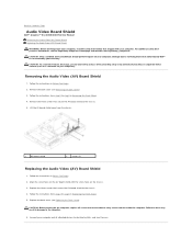
... Make note of the AV board cable routing and release the cable from the routing guide. Damage due to step 5 in Removing the Front Stand. 4. Remove the back cover (see Removing the Display Panel). 9. Remove the display panel (see Removing the Back Cover). 3. Replace the ... Route the AV board cable through the routing guide and secure it with your computer. Back to Contents Page Audio Video Board Cable Dell™ Inspiron™ One 2305/2310 Service Manual Removing the Audio Video (AV) Board Cable Replacing the Audio Video (AV) Board Cable WARNING: Before working inside...
... Make note of the AV board cable routing and release the cable from the routing guide. Damage due to step 5 in Removing the Front Stand. 4. Remove the back cover (see Removing the Display Panel). 9. Remove the display panel (see Removing the Back Cover). 3. Replace the ... Route the AV board cable through the routing guide and secure it with your computer. Back to Contents Page Audio Video Board Cable Dell™ Inspiron™ One 2305/2310 Service Manual Removing the Audio Video (AV) Board Cable Replacing the Audio Video (AV) Board Cable WARNING: Before working inside...

Service Manual
Page 7
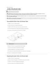
..., and turn them on the AV board. 7. Follow the instructions from step 4 to step 5 in damage to do so may result in Replacing the Front Stand. 9. Failure to the computer. 10. Connect the AV board cable to Contents Page
..., and turn them on the AV board. 7. Follow the instructions from step 4 to step 5 in damage to do so may result in Replacing the Front Stand. 9. Failure to the computer. 10. Connect the AV board cable to Contents Page
Service Manual
Page 8
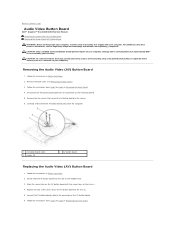
... Audio Video Button Board Dell™ Inspiron™ One 2305/2310 Service Manual Removing the Audio Video (AV) Button Board Replacing the Audio Video (AV) Button Board WARNING: Before working inside your computer, read the safety information that is not authorized by Dell™ is not covered...to the chassis. 6. Follow the instructions from the connector on the AV button board. 6. Follow the instructions in Replacing the Front Stand. Align the screw holes on the AV button board with your computer. For additional safety best practices information, see Removing the Back Cover...
... Audio Video Button Board Dell™ Inspiron™ One 2305/2310 Service Manual Removing the Audio Video (AV) Button Board Replacing the Audio Video (AV) Button Board WARNING: Before working inside your computer, read the safety information that is not authorized by Dell™ is not covered...to the chassis. 6. Follow the instructions from the connector on the AV button board. 6. Follow the instructions in Replacing the Front Stand. Align the screw holes on the AV button board with your computer. For additional safety best practices information, see Removing the Back Cover...
Service Manual
Page 12
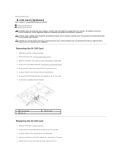
Removing the B-CAS Card 1. Remove the two screws that secure the B-CAS card to servicing that is not authorized by Dell™ is not covered by periodically touching an unpainted metal surface (such as a connector on your computer. Disconnect the B-CAS-card ...Begin. 2. Back to the connector on the TV tuner card. 3. Connect the B-CAS-card cable to Contents Page B-CAS Card (Optional) Dell™ Inspiron™ One 2305/2310 Service Manual Removing the B-CAS Card Replacing the B-CAS Card WARNING: Before working inside your computer, read the safety information that secure the...
Removing the B-CAS Card 1. Remove the two screws that secure the B-CAS card to servicing that is not authorized by Dell™ is not covered by periodically touching an unpainted metal surface (such as a connector on your computer. Disconnect the B-CAS-card ...Begin. 2. Back to the connector on the TV tuner card. 3. Connect the B-CAS-card cable to Contents Page B-CAS Card (Optional) Dell™ Inspiron™ One 2305/2310 Service Manual Removing the B-CAS Card Replacing the B-CAS Card WARNING: Before working inside your computer, read the safety information that secure the...
Service Manual
Page 13
Replace the back cover (see Removing the System-Board Shield). 7. CAUTION: Before turning on . Back to step 5 in damage to electrical outlets, and turn them on the computer, replace all attached devices to the computer. 9. Follow the instructions from step 4 to Contents Page Replace the system-board shield (see Replacing the Back Cover). 6. Failure to do so may result in Replacing the Front Stand. 8. Connect your computer and all screws and ensure that no stray screws remain inside the computer.
Replace the back cover (see Removing the System-Board Shield). 7. CAUTION: Before turning on . Back to step 5 in damage to electrical outlets, and turn them on the computer, replace all attached devices to the computer. 9. Follow the instructions from step 4 to Contents Page Replace the system-board shield (see Replacing the Back Cover). 6. Failure to do so may result in Replacing the Front Stand. 8. Connect your computer and all screws and ensure that no stray screws remain inside the computer.
Service Manual
Page 21
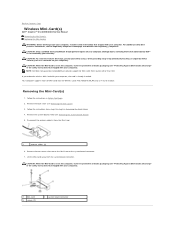
..., store it in protective antistatic packaging (see "Protecting Against Electrostatic Discharge" in Removing the Front Stand. 4. Follow the instructions from sources other than Dell. Damage due to servicing that shipped with your computer. CAUTION: To avoid electrostatic discharge, ground ... Lift the Mini-Card away from the Mini-Card. 1 antenna cables (2) 6. Back to Contents Page Wireless Mini-Card(s) Dell™ Inspiron™ One 2305/2310 Service Manual Removing the Mini-Card(s) Replacing the Mini-Card(s) WARNING: Before working inside your computer, read the safety ...
..., store it in protective antistatic packaging (see "Protecting Against Electrostatic Discharge" in Removing the Front Stand. 4. Follow the instructions from sources other than Dell. Damage due to servicing that shipped with your computer. CAUTION: To avoid electrostatic discharge, ground ... Lift the Mini-Card away from the Mini-Card. 1 antenna cables (2) 6. Back to Contents Page Wireless Mini-Card(s) Dell™ Inspiron™ One 2305/2310 Service Manual Removing the Mini-Card(s) Replacing the Mini-Card(s) WARNING: Before working inside your computer, read the safety ...
Service Manual
Page 22
... all attached devices to the system-board connector. 5. CAUTION: To avoid damage to step 5 in Before You Begin. 2. Follow the instructions in Replacing the Front Stand. 8. Replace the system-board shield (see Replacing the Back Cover). Connect your computer.
... all attached devices to the system-board connector. 5. CAUTION: To avoid damage to step 5 in Before You Begin. 2. Follow the instructions in Replacing the Front Stand. 8. Replace the system-board shield (see Replacing the Back Cover). Connect your computer.
Service Manual
Page 23
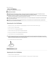
... (such as a connector on your computer. Press the battery release lever to the manufacturer's instructions. Follow the instructions in Removing the Front Stand. 5. Discard used batteries according to remove the battery. 1 battery release lever Replacing the Coin-Cell Battery 1. Removing the Coin-Cell Battery... the instructions from step 2 to step 5 in Before You Begin. 2. Back to Contents Page Coin-Cell Battery Dell™ Inspiron™ One 2305/2310 Service Manual Removing the Coin-Cell Battery Replacing the Coin-Cell Battery WARNING: Before working inside your computer, read...
... (such as a connector on your computer. Press the battery release lever to the manufacturer's instructions. Follow the instructions in Removing the Front Stand. 5. Discard used batteries according to remove the battery. 1 battery release lever Replacing the Coin-Cell Battery 1. Removing the Coin-Cell Battery... the instructions from step 2 to step 5 in Before You Begin. 2. Back to Contents Page Coin-Cell Battery Dell™ Inspiron™ One 2305/2310 Service Manual Removing the Coin-Cell Battery Replacing the Coin-Cell Battery WARNING: Before working inside your computer, read...

Service Manual
Page 24
Replace the back cover (see System Setup Utility) and restore the settings you recorded in Replacing the Front Stand. 5. Enter the system setup utility (see Replacing the Back Cover). Follow the instructions from step 4 to the computer. 6. Failure to do so may result in ...
Replace the back cover (see System Setup Utility) and restore the settings you recorded in Replacing the Front Stand. 5. Enter the system setup utility (see Replacing the Back Cover). Follow the instructions from step 4 to the computer. 6. Failure to do so may result in ...
Service Manual
Page 33
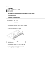
..., ground yourself by using a wrist grounding strap or by your warranty. Remove the four screws that shipped with your computer. Back to Contents Page Front Stand Dell™ Inspiron™ One 2305/2310 Service Manual Removing the Front Stand Replacing the Front Stand WARNING: Before working inside your computer, read the safety information that secure the front...
..., ground yourself by using a wrist grounding strap or by your warranty. Remove the four screws that shipped with your computer. Back to Contents Page Front Stand Dell™ Inspiron™ One 2305/2310 Service Manual Removing the Front Stand Replacing the Front Stand WARNING: Before working inside your computer, read the safety information that secure the front...

Service Manual
Page 34
Follow the instructions in damage to electrical outlets, and turn them on. Align the screw holes on the front-stand assembly with the screw holes on the computer. 5. CAUTION: Before turning on the computer, replace all attached devices to the computer... Slide the five tabs on the I /O bracket 2 screws (2) 4 tabs (5) Replacing the Front Stand 1. Replace the back cover (see Replacing the Back Cover). 1 front stand 3 I /O bracket into the slots on the front stand. 3. Back to the front stand. 4. Failure to the computer. 6. Replace the two screws that secure the front...
Follow the instructions in damage to electrical outlets, and turn them on. Align the screw holes on the front-stand assembly with the screw holes on the computer. 5. CAUTION: Before turning on the computer, replace all attached devices to the computer... Slide the five tabs on the I /O bracket 2 screws (2) 4 tabs (5) Replacing the Front Stand 1. Replace the back cover (see Replacing the Back Cover). 1 front stand 3 I /O bracket into the slots on the front stand. 3. Back to the front stand. 4. Failure to the computer. 6. Replace the two screws that secure the front...
Service Manual
Page 37
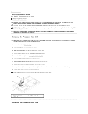
... sink), loosen the four captive screws that secure the processor heat sink to the system board. 10. The oils in Removing the Front Stand. 4. Remove the two screws that it has had sufficient time to cool before you touch it. WARNING: The heat sink may vary ... information, see Removing the MXM Assembly). 7. NOTE: The appearance of the thermal grease. 1. Back to Contents Page Processor Heat-Sink Dell™ Inspiron™ One 2305/2310 Service Manual Removing the Processor Heat Sink Replacing the Processor Heat Sink WARNING: Before working inside your computer, read the safety information ...
... sink), loosen the four captive screws that secure the processor heat sink to the system board. 10. The oils in Removing the Front Stand. 4. Remove the two screws that it has had sufficient time to cool before you touch it. WARNING: The heat sink may vary ... information, see Removing the MXM Assembly). 7. NOTE: The appearance of the thermal grease. 1. Back to Contents Page Processor Heat-Sink Dell™ Inspiron™ One 2305/2310 Service Manual Removing the Processor Heat Sink Replacing the Processor Heat Sink WARNING: Before working inside your computer, read the safety information ...

Service Manual
Page 38
..., and turn them on the computer, replace all screws and ensure that thermal conductivity is replaced, use the thermal grease provided in Replacing the Front Stand. 10. Clean the thermal grease from step 4 to the system board and processor. Replace the MXM assembly (see Replacing the MXM-Assembly Fan). 8. CAUTION: Incorrect...
..., and turn them on the computer, replace all screws and ensure that thermal conductivity is replaced, use the thermal grease provided in Replacing the Front Stand. 10. Clean the thermal grease from step 4 to the system board and processor. Replace the MXM assembly (see Replacing the MXM-Assembly Fan). 8. CAUTION: Incorrect...


