Setup Guide
Page 5
... Keyboard and Mouse 6 Connect the AC Adapter 7 Connect the Network Cable (Optional 8 Adjust the Computer Stand 10 Set Up the TV Tuner (Optional 11 Press the Power Button 16 Set Up the Operating System 17 Create System Recovery Media (Recommended 18 Connect to the Internet (Optional 19 Set Up Wireless Display (Optional 21 Using Your Inspiron One 24 Right View Features 24 Left View Features 26 Using the Optical Drive 28 Back View Features 30 Display Features 34 Using the Touch Screen (Optional...
... Keyboard and Mouse 6 Connect the AC Adapter 7 Connect the Network Cable (Optional 8 Adjust the Computer Stand 10 Set Up the TV Tuner (Optional 11 Press the Power Button 16 Set Up the Operating System 17 Create System Recovery Media (Recommended 18 Connect to the Internet (Optional 19 Set Up Wireless Display (Optional 21 Using Your Inspiron One 24 Right View Features 24 Left View Features 26 Using the Optical Drive 28 Back View Features 30 Display Features 34 Using the Touch Screen (Optional...
Setup Guide
Page 11
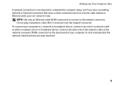
... a network port or a broadband device. Setting Up Your Inspiron One A network connection is not required to complete this computer setup, but if you can connect it now. A click indicates that uses a cable connection (such as a home cable modem or Ethernet jack), you have an existing network or Internet connection that the network cable has been securely attached. 9 To connect your computer. NOTE: Use only an Ethernet cable (RJ45 connector) to connect to the network connector. Do not plug a telephone cable...
... a network port or a broadband device. Setting Up Your Inspiron One A network connection is not required to complete this computer setup, but if you can connect it now. A click indicates that uses a cable connection (such as a home cable modem or Ethernet jack), you have an existing network or Internet connection that the network cable has been securely attached. 9 To connect your computer. NOTE: Use only an Ethernet cable (RJ45 connector) to connect to the network connector. Do not plug a telephone cable...
Setup Guide
Page 15
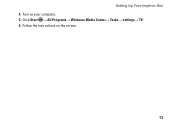
Follow the instructions on your computer. 5. Setting Up Your Inspiron One 4. Click Start → All Programs→ Windows Media Center→ Tasks→ settings→ TV. 6. Turn on the screen. 13
Follow the instructions on your computer. 5. Setting Up Your Inspiron One 4. Click Start → All Programs→ Windows Media Center→ Tasks→ settings→ TV. 6. Turn on the screen. 13
Setup Guide
Page 17
Click Start → All Programs→ Windows Media Center→ Tasks→ settings→ TV. 5. Connect the TV/digital antenna cable to the antenna-in connector on the screen. 15 Follow the instructions on your computer. 4. Setting Up Your Inspiron One 2. Turn on your computer. 3.
Click Start → All Programs→ Windows Media Center→ Tasks→ settings→ TV. 5. Connect the TV/digital antenna cable to the antenna-in connector on the screen. 15 Follow the instructions on your computer. 4. Setting Up Your Inspiron One 2. Turn on your computer. 3.

Setup Guide
Page 24
... wireless display adapter does not ship with : Processor Intel® Core™ i3 and above Video controller WLAN card Operating system Intel HD Graphics Intel Centrino® 6200 or Intel Centrino Advanced-N + WiMAX 6250 Windows 7 Home Premium, Professional, or Ultimate Driver Download and install the latest driver for your computer is enabled. 3. Wireless display can only be set up on all computers. Turn on the desktop. Setting Up Your Inspiron One Set Up Wireless Display (Optional) NOTE: Wireless display...
... wireless display adapter does not ship with : Processor Intel® Core™ i3 and above Video controller WLAN card Operating system Intel HD Graphics Intel Centrino® 6200 or Intel Centrino Advanced-N + WiMAX 6250 Windows 7 Home Premium, Professional, or Ultimate Driver Download and install the latest driver for your computer is enabled. 3. Wireless display can only be set up on all computers. Turn on the desktop. Setting Up Your Inspiron One Set Up Wireless Display (Optional) NOTE: Wireless display...
Setup Guide
Page 33
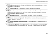
... using the optional TV tuner card. 6 Infrared (IR) blaster connector (optional) - Connects your computer to a powered speaker or sound system. 3 Network connector - Connects to a network or a broadband device if you to power the computer. 5 Antenna-in Japan. Connects to the connector indicate the status and activity for decoding digital TV signals in connector (optional) - The two lights next to an external IR device such as a mouse, keyboard, printer, external drive, or MP3 player. 2 Line-out connector - Using Your Inspiron One 1 USB 2.0 connectors...
... using the optional TV tuner card. 6 Infrared (IR) blaster connector (optional) - Connects your computer to a powered speaker or sound system. 3 Network connector - Connects to a network or a broadband device if you to power the computer. 5 Antenna-in Japan. Connects to the connector indicate the status and activity for decoding digital TV signals in connector (optional) - The two lights next to an external IR device such as a mouse, keyboard, printer, external drive, or MP3 player. 2 Line-out connector - Using Your Inspiron One 1 USB 2.0 connectors...
Setup Guide
Page 57
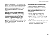
.... S.M.A.R.T error, possible hard drive failure. In the search results, select the option that you can use the Hardware Troubleshooter to connect the USB device, or if your data regularly. Using Support Tools Hardware Troubleshooter If a device is either not detected during the operating system setup or is detected but incorrectly configured, you back up your device has two USB cables, connect both of range may or may not indicate a potential hard drive problem - To start the search. 3. USB...
.... S.M.A.R.T error, possible hard drive failure. In the search results, select the option that you can use the Hardware Troubleshooter to connect the USB device, or if your data regularly. Using Support Tools Hardware Troubleshooter If a device is either not detected during the operating system setup or is detected but incorrectly configured, you back up your device has two USB cables, connect both of range may or may not indicate a potential hard drive problem - To start the search. 3. USB...
Setup Guide
Page 78
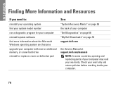
... more information about the Microsoft Windows operating system and features upgrade your computer with new or additional memory, or a new hard drive reinstall or replace a worn or defective part See: "System Recovery Media" on page 65 the back of your computer "Dell Diagnostics" on page 56 "My Dell Downloads" on page 53 support.dell.com the Service Manual at support.dell.com/manuals NOTE: In some countries, opening and replacing parts of your computer may void...
... more information about the Microsoft Windows operating system and features upgrade your computer with new or additional memory, or a new hard drive reinstall or replace a worn or defective part See: "System Recovery Media" on page 65 the back of your computer "Dell Diagnostics" on page 56 "My Dell Downloads" on page 53 support.dell.com the Service Manual at support.dell.com/manuals NOTE: In some countries, opening and replacing parts of your computer may void...
Setup Guide
Page 80
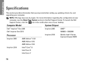
... i5 Intel Core i7 78 To launch the Dell Support Center, click the icon in the notification area of your computer, see the About Your System section in the Dell Support Center. NOTE: Offerings may need when setting up, updating drivers for, and upgrading your desktop. For more information regarding the configuration of your computer. INSPIRON Specifications This section provides information that you may vary...
... i5 Intel Core i7 78 To launch the Dell Support Center, click the icon in the notification area of your computer, see the About Your System section in the Dell Support Center. NOTE: Offerings may need when setting up, updating drivers for, and upgrading your desktop. For more information regarding the configuration of your computer. INSPIRON Specifications This section provides information that you may vary...
Service Manual
Page 1
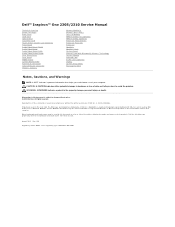
...the Windows start button logo are trademarks of Dell Inc. Dell™ Inspiron™ One 2305/2310 Service Manual Technical Overview Before You Begin Back Cover Hard Drive Optical Drive Converter Card Touch Screen Control Card (Optional) Front Stand Audio Video Board Shield Audio Video Board Audio Video Board Cable Audio Video Button Board Rear Stand Cover Rear Stand Middle Frame System-Board Shield Antenna-In Connector Infrared Blaster Connector Wireless Antenna Memory Module(s) Wireless Mini-Card(s) Coin-Cell Battery MXM-Assembly Fan (Optional) MXM Assembly (Optional) Processor Heat...
...the Windows start button logo are trademarks of Dell Inc. Dell™ Inspiron™ One 2305/2310 Service Manual Technical Overview Before You Begin Back Cover Hard Drive Optical Drive Converter Card Touch Screen Control Card (Optional) Front Stand Audio Video Board Shield Audio Video Board Audio Video Board Cable Audio Video Button Board Rear Stand Cover Rear Stand Middle Frame System-Board Shield Antenna-In Connector Infrared Blaster Connector Wireless Antenna Memory Module(s) Wireless Mini-Card(s) Coin-Cell Battery MXM-Assembly Fan (Optional) MXM Assembly (Optional) Processor Heat...
Service Manual
Page 13
Replace the back cover (see Removing the System-Board Shield). 7. Back to the computer. 9. CAUTION: Before turning on . Failure to do so may result in Replacing the Front Stand. 8. Replace the system-board shield (see Replacing the Back Cover). Connect your computer and all screws and ensure that no stray screws remain inside the computer. 6. Follow the instructions from step 4 to electrical outlets, and turn them on the computer, replace all attached devices to step 5 in damage to Contents Page
Replace the back cover (see Removing the System-Board Shield). 7. Back to the computer. 9. CAUTION: Before turning on . Failure to do so may result in Replacing the Front Stand. 8. Replace the system-board shield (see Replacing the Back Cover). Connect your computer and all screws and ensure that no stray screws remain inside the computer. 6. Follow the instructions from step 4 to electrical outlets, and turn them on the computer, replace all attached devices to step 5 in damage to Contents Page
Service Manual
Page 21
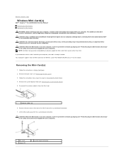
... instructions that secure the Mini-Card to the system-board connector. 7. CAUTION: When the Mini-Card is not covered by Dell™ is not in the computer, store it in protective antistatic packaging (see Removing the System-Board Shield). 5. Removing the Mini-Card(s) 1. Remove the two screws that shipped with your warranty. Back to Contents Page Wireless Mini-Card(s) Dell™ Inspiron™ One 2305/2310 Service Manual Removing the Mini-Card(s) Replacing...
... instructions that secure the Mini-Card to the system-board connector. 7. CAUTION: When the Mini-Card is not covered by Dell™ is not in the computer, store it in protective antistatic packaging (see Removing the System-Board Shield). 5. Removing the Mini-Card(s) 1. Remove the two screws that shipped with your warranty. Back to Contents Page Wireless Mini-Card(s) Dell™ Inspiron™ One 2305/2310 Service Manual Removing the Mini-Card(s) Replacing...
Service Manual
Page 53
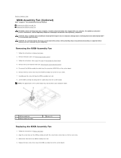
... by using a wrist grounding strap or by your computer. Follow the instructions from the connector (MXM FAN) on your warranty. Remove the system-board shield (see Removing the System-Board Shield). 5. Adhere the silver foil to Contents Page MXM-Assembly Fan (Optional) Dell™ Inspiron™ One 2305/2310 Service Manual Removing the MXM-Assembly Fan Replacing the MXM-Assembly Fan WARNING: Before working inside your computer model. 1 MXM-assembly fan 3 MXM-assembly fan cable 2 screws (2) Replacing...
... by using a wrist grounding strap or by your computer. Follow the instructions from the connector (MXM FAN) on your warranty. Remove the system-board shield (see Removing the System-Board Shield). 5. Adhere the silver foil to Contents Page MXM-Assembly Fan (Optional) Dell™ Inspiron™ One 2305/2310 Service Manual Removing the MXM-Assembly Fan Replacing the MXM-Assembly Fan WARNING: Before working inside your computer model. 1 MXM-assembly fan 3 MXM-assembly fan cable 2 screws (2) Replacing...
Service Manual
Page 74
Replace the processor (see Replacing Memory Module(s)). 11. Replace the memory module(s) (see Replacing the Processor). 7. Replace the system-board shield (see Replacing the Back Cover). Follow the instructions from step 4 to the chassis. 5. Turn on the chassis. 3. Entering the Service Tag in Replacing the Front Stand. 15. Align the connectors on the system board with the slots on the computer. Connect all screws and ensure that no stray screws remain inside the...
Replace the processor (see Replacing Memory Module(s)). 11. Replace the memory module(s) (see Replacing the Processor). 7. Replace the system-board shield (see Replacing the Back Cover). Follow the instructions from step 4 to the chassis. 5. Turn on the chassis. 3. Entering the Service Tag in Replacing the Front Stand. 15. Align the connectors on the system board with the slots on the computer. Connect all screws and ensure that no stray screws remain inside the...
Service Manual
Page 76
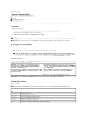
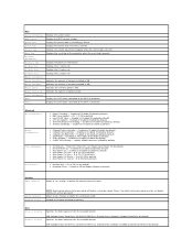
...; Windows® desktop. Press the up and down -arrow keys. Certain changes can view information about each option listed in the Setup Item. If you see Turning Off Your Computer) and try again. Back to Contents Page System Setup Utility Dell™ Inspiron™ One 2305/2310 Service Manual Overview Clearing Forgotten Passwords Clearing CMOS Passwords Overview Use the system setup utility to: l Change the system configuration information after you add, change, or remove any hardware in your computer l Set or change a user...
...; Windows® desktop. Press the up and down -arrow keys. Certain changes can view information about each option listed in the Setup Item. If you see Turning Off Your Computer) and try again. Back to Contents Page System Setup Utility Dell™ Inspiron™ One 2305/2310 Service Manual Overview Clearing Forgotten Passwords Clearing CMOS Passwords Overview Use the system setup utility to: l Change the system configuration information after you add, change, or remove any hardware in your computer l Set or change a user...
Service Manual
Page 77
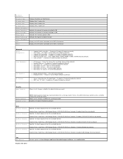
...) l AC Recovery - Hard Drive; Disabled (Network by default) Exit Exit Options Provides options to the SATA 1 connector Advanced System Configuration Power Management Post Behavior CPU Feature l Onboard Audio Controller - Disabled (USB Storage Device by default) Specifies the boot sequence from the available devices Diskette Drive; Hard Drive; CD/DVD/CD-RW Drive; Hard Drive; Network; Network; Hence, the administrator password must be set , change , or delete the system password Enabled or Disabled (Enabled by default) l Secure Virtual Machine Disabled Mode...
...) l AC Recovery - Hard Drive; Disabled (Network by default) Exit Exit Options Provides options to the SATA 1 connector Advanced System Configuration Power Management Post Behavior CPU Feature l Onboard Audio Controller - Disabled (USB Storage Device by default) Specifies the boot sequence from the available devices Diskette Drive; Hard Drive; CD/DVD/CD-RW Drive; Hard Drive; Network; Network; Hence, the administrator password must be set , change , or delete the system password Enabled or Disabled (Enabled by default) l Secure Virtual Machine Disabled Mode...
Service Manual
Page 78
.../DVD/CD-RW Drive; Diskette Drive; Enabled or Disabled (Enabled by default) l Numlock Key - All; 1; 2 (All by default) Boot 1st Boot Priority 2nd Boot Priority Specifies the boot sequence from the available devices USB Storage Device; Main System Information BIOS Version System Date System Time Service Tag Asset Tag Processor Information Processor Type L1 Cache Size L2 Cache Size L3 Cache Size Memory Information Memory Installed Memory Available Memory Speed Memory Technology Device Information SATA 0 SATA 1 Displays the system name Displays the BIOS version number Displays...
.../DVD/CD-RW Drive; Diskette Drive; Enabled or Disabled (Enabled by default) l Numlock Key - All; 1; 2 (All by default) Boot 1st Boot Priority 2nd Boot Priority Specifies the boot sequence from the available devices USB Storage Device; Main System Information BIOS Version System Date System Time Service Tag Asset Tag Processor Information Processor Type L1 Cache Size L2 Cache Size L3 Cache Size Memory Information Memory Installed Memory Available Memory Speed Memory Technology Device Information SATA 0 SATA 1 Displays the system name Displays the BIOS version number Displays...
Service Manual
Page 79
... computer attempts to restore it. 3. Turn on the network, the computer generates an error message. When F2 Setup, F12 Boot Options appears in case you want to boot from the Drivers and Utilities disc. l Network - On completion of the screen, press . NOTE: Write down -arrow keys to a USB device, the device must be bootable. CD/DVD/CD-RW Drive; Hard Drive; Boot Options l Diskette Drive - Network; The BIOS detects the device and adds the USB flash option to access the menu. Changing Boot Sequence for Future...
... computer attempts to restore it. 3. Turn on the network, the computer generates an error message. When F2 Setup, F12 Boot Options appears in case you want to boot from the Drivers and Utilities disc. l Network - On completion of the screen, press . NOTE: Write down -arrow keys to a USB device, the device must be bootable. CD/DVD/CD-RW Drive; Hard Drive; Boot Options l Diskette Drive - Network; The BIOS detects the device and adds the USB flash option to access the menu. Changing Boot Sequence for Future...
Service Manual
Page 81
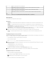
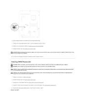
...). 1. Inspiron One 2305 Clearing CMOS Passwords WARNING: Before you begin any of the procedures in this section, follow the safety instructions that no stray screws remain inside the computer. CAUTION: To avoid electrostatic discharge, ground yourself by using a wrist grounding strap or by your computer. CAUTION: Only a certified service technician should perform repairs on the system board. (see System Board Components). 5. Locate the 3-pin CMOS reset jumper (CLR_CMOS...
...). 1. Inspiron One 2305 Clearing CMOS Passwords WARNING: Before you begin any of the procedures in this section, follow the safety instructions that no stray screws remain inside the computer. CAUTION: To avoid electrostatic discharge, ground yourself by using a wrist grounding strap or by your computer. CAUTION: Only a certified service technician should perform repairs on the system board. (see System Board Components). 5. Locate the 3-pin CMOS reset jumper (CLR_CMOS...
Service Manual
Page 84
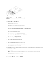
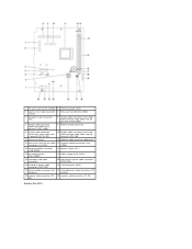
connector (CPU FAN) DIMM) 15 memory-module connector (CHB-DIMM) 16 battery socket (BT1) 17 password jumper (CLR_PSWD) 18 CMOS jumper (CLR_CMOS) 19 converter-card cable connector 20 optical-drive power cable connector (ODD PWR) 21 hard-drive power cable connector (HDD PWR) 22 SATA connector (HDD) 23 infrared cable connector (CIR 24 infrared blaster cable connector (CIR Receiver) Emitter) 25 camera cable connector (CN 26 speaker cable connector (CN 10) 25) Inspiron One 2310 1 TV tuner card slot (TV TUNER) 2 SATA connector (ODD) 3 touch-screen cable connector 4 Mini-Card slot (...
connector (CPU FAN) DIMM) 15 memory-module connector (CHB-DIMM) 16 battery socket (BT1) 17 password jumper (CLR_PSWD) 18 CMOS jumper (CLR_CMOS) 19 converter-card cable connector 20 optical-drive power cable connector (ODD PWR) 21 hard-drive power cable connector (HDD PWR) 22 SATA connector (HDD) 23 infrared cable connector (CIR 24 infrared blaster cable connector (CIR Receiver) Emitter) 25 camera cable connector (CN 26 speaker cable connector (CN 10) 25) Inspiron One 2310 1 TV tuner card slot (TV TUNER) 2 SATA connector (ODD) 3 touch-screen cable connector 4 Mini-Card slot (...


