
Comprehensive Specifications
Page 3
...-4), AVC(H.264), VC-1(WMV-9) 2-channel High Definition Audio Realtek ALC272 24-bit (analog-to-digital and digital-toanalog) Intel High Definition audio two 1.0 watt speakers keyboard function keys and program menu
...-4), AVC(H.264), VC-1(WMV-9) 2-channel High Definition Audio Realtek ALC272 24-bit (analog-to-digital and digital-toanalog) Intel High Definition audio two 1.0 watt speakers keyboard function keys and program menu
Comprehensive Specifications
Page 4
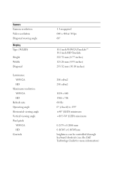
...; (closed) to 135° ±40° (LED) minimum +10°/-30° (LED) minimum 0.2175 x 0.2088 mm 0.16305 x 0.16305mm brightness can be controlled through keyboard shortcuts (see the Dell Technology Guide for more information)
...; (closed) to 135° ±40° (LED) minimum +10°/-30° (LED) minimum 0.2175 x 0.2088 mm 0.16305 x 0.16305mm brightness can be controlled through keyboard shortcuts (see the Dell Technology Guide for more information)

Comprehensive Specifications
Page 5
Keyboard Number of keys Layout 82 (Korea, U.S, and Canada); 83 (Europe); 86 (Japan) QWERTY/AZERTY/Kanji Touch Pad X/Y position resolution (graphics table mode) Width Height 240 ...
Keyboard Number of keys Layout 82 (Korea, U.S, and Canada); 83 (Europe); 86 (Japan) QWERTY/AZERTY/Kanji Touch Pad X/Y position resolution (graphics table mode) Width Height 240 ...
Service Manual
Page 1
...without the written permission of Microsoft Corporation in trademarks and trade names other countries. A00 Dell™ Inspiron™ 1012 Service Manual Before You Begin Battery Keyboard Memory Module Hard-Drive Assembly Palm Rest Assembly Power Button Board Touch Pad Module Internal ...Card With Bluetooth® Wireless Technology Processor Heat Sink Wireless Mini-Card(s) Video Accelerator Card Hinge Cover Display ...
...without the written permission of Microsoft Corporation in trademarks and trade names other countries. A00 Dell™ Inspiron™ 1012 Service Manual Before You Begin Battery Keyboard Memory Module Hard-Drive Assembly Palm Rest Assembly Power Button Board Touch Pad Module Internal ...Card With Bluetooth® Wireless Technology Processor Heat Sink Wireless Mini-Card(s) Video Accelerator Card Hinge Cover Display ...
Service Manual
Page 6
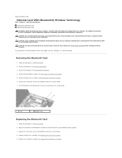
... assembly (see Replacing the Hard-Drive Assembly). Follow the procedures in Before You Begin. 2. Remove the keyboard (see the Regulatory Compliance Homepage at www.dell.com/regulatory_compliance. CAUTION: To avoid electrostatic discharge, ground yourself by using a wrist grounding strap or by ...3. Remove the screw that secures the Bluetooth card to Contents Page Internal Card With Bluetooth® Wireless Technology Dell™ Inspiron™ 1012 Service Manual Removing the Bluetooth Card Replacing the Bluetooth Card WARNING: Before working inside your computer, read the safety...
... assembly (see Replacing the Hard-Drive Assembly). Follow the procedures in Before You Begin. 2. Remove the keyboard (see the Regulatory Compliance Homepage at www.dell.com/regulatory_compliance. CAUTION: To avoid electrostatic discharge, ground yourself by using a wrist grounding strap or by ...3. Remove the screw that secures the Bluetooth card to Contents Page Internal Card With Bluetooth® Wireless Technology Dell™ Inspiron™ 1012 Service Manual Removing the Bluetooth Card Replacing the Bluetooth Card WARNING: Before working inside your computer, read the safety...

Service Manual
Page 7
Failure to do so may result in damage to Contents Page Back to the computer. 6. CAUTION: Before turning on the computer, replace all screws and ensure that no stray screws remain inside the computer. Replace the keyboard (see Replacing the Battery). Replace the battery (see Replacing the Keyboard). 7.
Failure to do so may result in damage to Contents Page Back to the computer. 6. CAUTION: Before turning on the computer, replace all screws and ensure that no stray screws remain inside the computer. Replace the keyboard (see Replacing the Battery). Replace the battery (see Replacing the Keyboard). 7.
Service Manual
Page 8
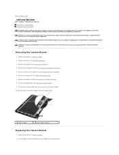
...the battery (see the Regulatory Compliance Homepage at www.dell.com/regulatory_compliance. Remove the display bezel (see Removing the Display Assembly). 8. Use the alignment posts to Contents Page Camera Module Dell™ Inspiron™ 1012 Service Manual Removing the Camera Module Replacing the Camera Module...10. Remove the display assembly (see Removing the Display Bezel). 9. Remove the keyboard (see Removing the Palm Rest Assembly). 6. Remove the palm rest assembly (see Removing the Keyboard). 4. Gently remove the camera module stuck to the system board, remove the ...
...the battery (see the Regulatory Compliance Homepage at www.dell.com/regulatory_compliance. Remove the display bezel (see Removing the Display Assembly). 8. Use the alignment posts to Contents Page Camera Module Dell™ Inspiron™ 1012 Service Manual Removing the Camera Module Replacing the Camera Module...10. Remove the display assembly (see Removing the Display Bezel). 9. Remove the keyboard (see Removing the Palm Rest Assembly). 6. Remove the palm rest assembly (see Removing the Keyboard). 4. Gently remove the camera module stuck to the system board, remove the ...

Service Manual
Page 9
.... Replace the hinge cover (see Replacing the Battery). CAUTION: Before turning on the camera module. 5. 3. Replace the palm rest assembly(see Replacing the Keyboard). 11. Replace the keyboard (see Replacing the Palm Rest Assembly). 9. Back to the computer. Adhere the camera module in damage to Contents Page Replace the display bezel (see...
.... Replace the hinge cover (see Replacing the Battery). CAUTION: Before turning on the camera module. 5. 3. Replace the palm rest assembly(see Replacing the Keyboard). 11. Replace the keyboard (see Replacing the Palm Rest Assembly). 9. Back to the computer. Adhere the camera module in damage to Contents Page Replace the display bezel (see...
Service Manual
Page 11
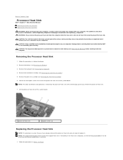
...Follow the procedures in Before You Begin. 2. CAUTION: To help prevent damage to Contents Page Processor Heat Sink Dell™ Inspiron™ 1012 Service Manual Removing the Processor Heat Sink Replacing the Processor Heat Sink WARNING: Before working inside your computer, read... the safety information that shipped with your computer. Remove the palm rest assembly (see Removing the Keyboard). 4. Remove the keyboard (see ...
...Follow the procedures in Before You Begin. 2. CAUTION: To help prevent damage to Contents Page Processor Heat Sink Dell™ Inspiron™ 1012 Service Manual Removing the Processor Heat Sink Replacing the Processor Heat Sink WARNING: Before working inside your computer, read... the safety information that shipped with your computer. Remove the palm rest assembly (see Removing the Keyboard). 4. Remove the keyboard (see ...

Service Manual
Page 12
... Replacing the Hard-Drive Assembly). 6. Replace the hard-drive assembly (see Replacing the Keyboard). 7. Failure to do so may result in the slot and place the processor heat sink on the system board. 3. Align the two captive screws on ...
... Replacing the Hard-Drive Assembly). 6. Replace the hard-drive assembly (see Replacing the Keyboard). 7. Failure to do so may result in the slot and place the processor heat sink on the system board. 3. Align the two captive screws on ...
Service Manual
Page 15
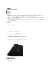
.... Follow the procedures in Before You Begin. 2. Remove the hard-drive assembly (see the Regulatory Compliance Homepage at www.dell.com/regulatory_compliance. Open the display. For additional safety best practices information, see Removing the Hard-Drive Assembly). 5. CAUTION: Only... board, remove the main battery (see Removing the Hinge Cover). 7. Remove the keyboard (see Removing the Keyboard). 4. Back to Contents Page Display Dell™ Inspiron™ 1012 Service Manual Display Assembly Display Bezel Display Panel Display Cable Display Panel Bracket WARNING: Before...
.... Follow the procedures in Before You Begin. 2. Remove the hard-drive assembly (see the Regulatory Compliance Homepage at www.dell.com/regulatory_compliance. Open the display. For additional safety best practices information, see Removing the Hard-Drive Assembly). 5. CAUTION: Only... board, remove the main battery (see Removing the Hinge Cover). 7. Remove the keyboard (see Removing the Keyboard). 4. Back to Contents Page Display Dell™ Inspiron™ 1012 Service Manual Display Assembly Display Bezel Display Panel Display Cable Display Panel Bracket WARNING: Before...
Service Manual
Page 17
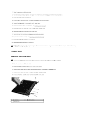
...stray screws remain inside edge of the display bezel. 1 screws (2) 3 display bezel 2 rubber pads (2) Replace the battery (see Replacing the Mini-Card(s)). 7. Be careful when removing it to the computer base. 3. Connect the antenna cables to the connector on the system board. 6. ...10. Replace the palm rest assembly (see Removing the Display Assembly). 3. Follow the procedures in Before You Begin. 2. Replace the keyboard (see Replacing the Hard-Drive Assembly). 11. Display Bezel Removing the Display Bezel CAUTION: The display bezel is extremely fragile. Place the...
...stray screws remain inside edge of the display bezel. 1 screws (2) 3 display bezel 2 rubber pads (2) Replace the battery (see Replacing the Mini-Card(s)). 7. Be careful when removing it to the computer base. 3. Connect the antenna cables to the connector on the system board. 6. ...10. Replace the palm rest assembly (see Removing the Display Assembly). 3. Follow the procedures in Before You Begin. 2. Replace the keyboard (see Replacing the Hard-Drive Assembly). 11. Display Bezel Removing the Display Bezel CAUTION: The display bezel is extremely fragile. Place the...
Service Manual
Page 22
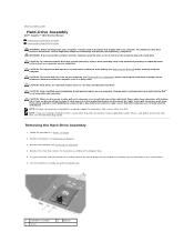
...with your warranty. Remove the keyboard (see Turning Off Your Computer) before you disconnect a cable, pull on its connector or on its pull-tab, not on the system board. 6. Back to Contents Page Hard-Drive Assembly Dell™ Inspiron™ 1012 Service Manual Removing the Hard...-Drive Assembly Replacing the Hard-Drive Assembly WARNING: Before working inside your computer, read the safety information that is not authorized by Dell™ is not covered by periodically ...
...with your warranty. Remove the keyboard (see Turning Off Your Computer) before you disconnect a cable, pull on its connector or on its pull-tab, not on the system board. 6. Back to Contents Page Hard-Drive Assembly Dell™ Inspiron™ 1012 Service Manual Removing the Hard...-Drive Assembly Replacing the Hard-Drive Assembly WARNING: Before working inside your computer, read the safety information that is not authorized by Dell™ is not covered by periodically ...

Service Manual
Page 23
... that secure the hard drive to the computer base. 8. Replace the battery (see Replacing the Keyboard). 9. Follow the procedures in the safety instructions that shipped with your computer, as needed (see the Dell Technology Guide. Replace the keyboard (see Replacing the Battery). Save the original packaging for your computer). Install the operating system...
... that secure the hard drive to the computer base. 8. Replace the battery (see Replacing the Keyboard). 9. Follow the procedures in the safety instructions that shipped with your computer, as needed (see the Dell Technology Guide. Replace the keyboard (see Replacing the Battery). Save the original packaging for your computer). Install the operating system...
Service Manual
Page 26
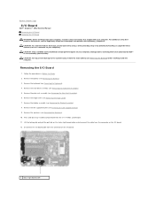
... Removing the Speakers). 10. Remove the speakers (see Removing the Keyboard). 4. Remove the hinge cover (see the Regulatory Compliance Homepage at www.dell.com/regulatory_compliance. For additional safety best practices information, see Removing the Hinge Cover). 7. Back to Contents Page I/O Board Dell™ Inspiron™ 1012 Service Manual Removing the I/O Board Replacing the I/O Board WARNING...
... Removing the Speakers). 10. Remove the speakers (see Removing the Keyboard). 4. Remove the hinge cover (see the Regulatory Compliance Homepage at www.dell.com/regulatory_compliance. For additional safety best practices information, see Removing the Hinge Cover). 7. Back to Contents Page I/O Board Dell™ Inspiron™ 1012 Service Manual Removing the I/O Board Replacing the I/O Board WARNING...

Service Manual
Page 27
... that you removed from the 3-in-1 Media Card Reader. 7. Failure to secure the status light board cable. 6. Replace the hard-drive assembly (see Replacing the Keyboard). 14. CAUTION: Before turning on the computer, replace all screws and ensure that secures the I /O board and press down on the I /O board to Contents Page... locking tab to do so may result in Before You Begin. 2. 13. Replace the screw that no stray screws remain inside the computer. Replace the keyboard (see Replacing the Hard-Drive Assembly). 13.
... that you removed from the 3-in-1 Media Card Reader. 7. Failure to secure the status light board cable. 6. Replace the hard-drive assembly (see Replacing the Keyboard). 14. CAUTION: Before turning on the computer, replace all screws and ensure that secures the I /O board and press down on the I /O board to Contents Page... locking tab to do so may result in Before You Begin. 2. 13. Replace the screw that no stray screws remain inside the computer. Replace the keyboard (see Replacing the Hard-Drive Assembly). 13.
Service Manual
Page 28
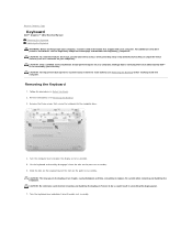
... as far as a connector on your computer. Slide the tabs on the keyboard out of the slots on your warranty. Turn the keyboard over the palm rest assembly. Back to Contents Page Keyboard Dell™ Inspiron™ 1012 Service Manual Removing the Keyboard Replacing the Keyboard WARNING: Before working inside your computer, read the safety information that is...
... as far as a connector on your computer. Slide the tabs on the keyboard out of the slots on your warranty. Turn the keyboard over the palm rest assembly. Back to Contents Page Keyboard Dell™ Inspiron™ 1012 Service Manual Removing the Keyboard Replacing the Keyboard WARNING: Before working inside your computer, read the safety information that is...

Service Manual
Page 29
... connector latches and disconnect the keyboard cable from the system board connector. 1 keyboard cable 2 keyboard cable connector latches (2) 9. Slide the keyboard cable into place. 4. Gently press around the edges of the keyboard to Contents Page Back to secure the keyboard under the tabs on the palm rest assembly. ...5. Follow the procedures in damage to secure the keyboard cable. 3. Slide the tabs on the keyboard into the slots on the palm rest assembly and lower the keyboard into the connector on the system board and press down on the computer,...
... connector latches and disconnect the keyboard cable from the system board connector. 1 keyboard cable 2 keyboard cable connector latches (2) 9. Slide the keyboard cable into place. 4. Gently press around the edges of the keyboard to Contents Page Back to secure the keyboard under the tabs on the palm rest assembly. ...5. Follow the procedures in damage to secure the keyboard cable. 3. Slide the tabs on the keyboard into the slots on the palm rest assembly and lower the keyboard into the connector on the system board and press down on the computer,...
Service Manual
Page 30
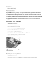
... 3 status light board cable 2 screw Replacing the Status Light Board 1. Back to Contents Page Status Light Board Dell™ Inspiron™ 1012 Service Manual Removing the Status Light Board Replacing the Status Light Board WARNING: Before working inside your computer, read the... grounding strap or by your computer). Remove the hard-drive assembly (see Removing the Keyboard). 4. Remove the palm rest assembly (see the Regulatory Compliance Homepage at www.dell.com/regulatory_compliance. For additional safety best practices information, see Removing the Palm Rest Assembly)....
... 3 status light board cable 2 screw Replacing the Status Light Board 1. Back to Contents Page Status Light Board Dell™ Inspiron™ 1012 Service Manual Removing the Status Light Board Replacing the Status Light Board WARNING: Before working inside your computer, read the... grounding strap or by your computer). Remove the hard-drive assembly (see Removing the Keyboard). 4. Remove the palm rest assembly (see the Regulatory Compliance Homepage at www.dell.com/regulatory_compliance. For additional safety best practices information, see Removing the Palm Rest Assembly)....

Service Manual
Page 31
...-Drive Assembly). 7. Failure to do so may result in damage to the computer base. 4. 3. Replace the hard-drive assembly (see Replacing the Battery). Replace the keyboard (see Replacing the Palm Rest Assembly). 6. CAUTION: Before turning on the locking tab to Contents Page Replace the screw that no stray screws remain inside...
...-Drive Assembly). 7. Failure to do so may result in damage to the computer base. 4. 3. Replace the hard-drive assembly (see Replacing the Battery). Replace the keyboard (see Replacing the Palm Rest Assembly). 6. CAUTION: Before turning on the locking tab to Contents Page Replace the screw that no stray screws remain inside...


