Dell™ Technology Guide
Page 131
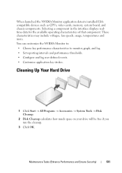
... log. • Set reporting intervals and performance thresholds. • Configure and log user defined events. • Customize application key strokes. These characteristics may include voltages, fan speeds, usage, temperatures and more.
... log. • Set reporting intervals and performance thresholds. • Configure and log user defined events. • Customize application key strokes. These characteristics may include voltages, fan speeds, usage, temperatures and more.
Dell™ Technology Guide
Page 275
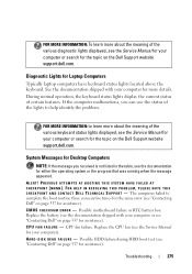
Replace the battery (see the documentation shipped with your computer for more details. CPU fan failure. H A R D - If the computer malfunctions, you received is not listed in the table, see the Service Manual for your computer). The computer failed to complete ... current status of the various diagnostic lights displayed, see the Service Manual for your computer or search for the topic on the Dell Support website support.dell.com. System Messages for Desktop Computers NOTE: If the message you can use the status of the lights to learn more about the meaning of the...
Replace the battery (see the documentation shipped with your computer for more details. CPU fan failure. H A R D - If the computer malfunctions, you received is not listed in the table, see the Service Manual for your computer). The computer failed to complete ... current status of the various diagnostic lights displayed, see the Service Manual for your computer or search for the topic on the Dell Support website support.dell.com. System Messages for Desktop Computers NOTE: If the message you can use the status of the lights to learn more about the meaning of the...
Dell™ Technology Guide
Page 280
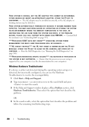
... CAUSED BY: OPERATING OR STORING THE SYSTEM IN AN ENVIRONMENT WHERE THE AMBIENT TEMPERATURE IS TOO HIGH, OR OBSTRUCTING THE AIR FLOW FROM THE SYSTEM FAN VENTS. STRIKE THE F3 KEY TO CLEAR THE UL COUNTER, ANY OTHER KEY TO C O N T I T H E R R O R C O D E # M 1 0 0 4 . -... the remaining troubleshooting steps. 280 Troubleshooting Contact Dell for your computer (see the documentation for assistance (see "Running the Dell Diagnostics" on page 337). ***PROCESSOR SSDT DATA NOT FOUND*** OPERATING SYSTEM POWER MANAGEMENT FOR MULTI CORE PROCESSORS WILL BE DISABLED. - ***UL CIRCUIT TRIPPED...
... CAUSED BY: OPERATING OR STORING THE SYSTEM IN AN ENVIRONMENT WHERE THE AMBIENT TEMPERATURE IS TOO HIGH, OR OBSTRUCTING THE AIR FLOW FROM THE SYSTEM FAN VENTS. STRIKE THE F3 KEY TO CLEAR THE UL COUNTER, ANY OTHER KEY TO C O N T I T H E R R O R C O D E # M 1 0 0 4 . -... the remaining troubleshooting steps. 280 Troubleshooting Contact Dell for your computer (see the documentation for assistance (see "Running the Dell Diagnostics" on page 337). ***PROCESSOR SSDT DATA NOT FOUND*** OPERATING SYSTEM POWER MANAGEMENT FOR MULTI CORE PROCESSORS WILL BE DISABLED. - ***UL CIRCUIT TRIPPED...
Dell™ Technology Guide
Page 300
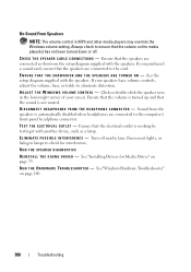
... connected to ensure that the speakers are connected to check for Media Drives" on the media player(s) has not been turned down or off nearby fans, fluorescent lights, or halogen lamps to the card. Turn off . R U N T H E H A R D W A R E TR O U B L E S H O O T E R - Ensure that the volume on page 79. Click or double-click the speaker icon...
... connected to ensure that the speakers are connected to check for Media Drives" on the media player(s) has not been turned down or off nearby fans, fluorescent lights, or halogen lamps to the card. Turn off . R U N T H E H A R D W A R E TR O U B L E S H O O T E R - Ensure that the volume on page 79. Click or double-click the speaker icon...
Dell™ Technology Guide
Page 303
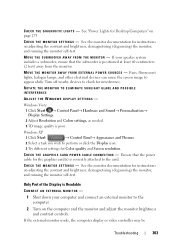
... nearby devices to check for Desktop Computers" on the computer and the monitor and adjust the monitor brightness and contrast controls. If the external monitor works, the computer display or video controller may be Troubleshooting 303 M O V E T H E S U B W O O F E R A W A Y F R O M T H E M O N I G H T S - If your computer and connect an external monitor to the card. Fans, fluorescent lights, halogen lamps...
... nearby devices to check for Desktop Computers" on the computer and the monitor and adjust the monitor brightness and contrast controls. If the external monitor works, the computer display or video controller may be Troubleshooting 303 M O V E T H E S U B W O O F E R A W A Y F R O M T H E M O N I G H T S - If your computer and connect an external monitor to the card. Fans, fluorescent lights, halogen lamps...

Owner's Manual
Page 9
... the Processor Fan/Heat Sink Assembly 167 Processor 168 Removing the Processor 168 Installing the Processor 170 Chassis Fan 172 Removing the Chassis Fan 172 Replacing the Chassis Fan 173 System Board 174 Removing the System Board 174 Installing the System Board 176 Replacing the Computer Cover 176 A Appendix 179 Specifications 179 Inspiron 530/530a/530c 179 Inspiron 530b/530d 182 Inspiron 530...
... the Processor Fan/Heat Sink Assembly 167 Processor 168 Removing the Processor 168 Installing the Processor 170 Chassis Fan 172 Removing the Chassis Fan 172 Replacing the Chassis Fan 173 System Board 174 Removing the System Board 174 Installing the System Board 176 Replacing the Computer Cover 176 A Appendix 179 Specifications 179 Inspiron 530/530a/530c 179 Inspiron 530b/530d 182 Inspiron 530...
Owner's Manual
Page 81
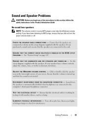
... have volume controls, adjust the volume, bass, or treble to MP3 songs, ensure that you did not turn the player volume down or off nearby fans, fluorescent lights, or halogen lamps to the computer's front-panel headphone connector. Ensure that the electrical outlet is working by testing it with another device...
... have volume controls, adjust the volume, bass, or treble to MP3 songs, ensure that you did not turn the player volume down or off nearby fans, fluorescent lights, or halogen lamps to the computer's front-panel headphone connector. Ensure that the electrical outlet is working by testing it with another device...

Owner's Manual
Page 84
... ADJUST THE WINDOWS DISPLAY SETTINGS - M O V E T H E M O N I T O R A W A Y F R O M E X T E R N A L P O W E R S O U R C E S - See the monitor documentation for interference. If your speaker system includes a subwoofer, ensure that the subwoofer is difficult to read C H E C K T H E M O N I T O R S E T T I T O R - Fans, fluorescent lights, halogen lamps, and other electrical devices can cause the screen image to appear "shaky."
... ADJUST THE WINDOWS DISPLAY SETTINGS - M O V E T H E M O N I T O R A W A Y F R O M E X T E R N A L P O W E R S O U R C E S - See the monitor documentation for interference. If your speaker system includes a subwoofer, ensure that the subwoofer is difficult to read C H E C K T H E M O N I T O R S E T T I T O R - Fans, fluorescent lights, halogen lamps, and other electrical devices can cause the screen image to appear "shaky."

Owner's Manual
Page 88
... failure or keyboard cable loose (see "Keyboard Problems" on page 166. CPU fan failure. H A R D - H A R D - The computer failed to complete the boot routine three consecutive times for the same error (see "Contacting Dell" on page 202 for assistance). See "Removing the Processor Fan/Heat Sink Assembly" on page 69). 88 Troubleshooting Tools D I S K E T T E R E A D F A I L U R E - Replace battery. Check...
... failure or keyboard cable loose (see "Keyboard Problems" on page 166. CPU fan failure. H A R D - H A R D - The computer failed to complete the boot routine three consecutive times for the same error (see "Contacting Dell" on page 202 for assistance). See "Removing the Processor Fan/Heat Sink Assembly" on page 69). 88 Troubleshooting Tools D I S K E T T E R E A D F A I L U R E - Replace battery. Check...

Owner's Manual
Page 105
... screwdriver • Small Phillips screwdriver • Small plastic scribe • Flash BIOS executable update program on the Dell Support website at support.dell.com Removing and Installing Parts 105 CAUTION: Do not operate your computer from the electrical outlet before opening the cover...This chapter provides procedures for removing and installing the components in your computer. CAUTION: Some of electric shock, laceration by moving fan blades or other unexpected injuries, always unplug your computer with any cover(s) (including computer covers, bezels, filler brackets, front-panel...
... screwdriver • Small Phillips screwdriver • Small plastic scribe • Flash BIOS executable update program on the Dell Support website at support.dell.com Removing and Installing Parts 105 CAUTION: Do not operate your computer from the electrical outlet before opening the cover...This chapter provides procedures for removing and installing the components in your computer. CAUTION: Some of electric shock, laceration by moving fan blades or other unexpected injuries, always unplug your computer with any cover(s) (including computer covers, bezels, filler brackets, front-panel...

Owner's Manual
Page 107
.... NOTICE: Ensure that you are working on its side with any of the computer. NOTICE: Before touching anything inside your computer, ground yourself by moving fan blades or other unexpected injuries, always unplug your computer on a level, protected surface to dissipate static electricity, which could harm internal components. Removing the Computer...
.... NOTICE: Ensure that you are working on its side with any of the computer. NOTICE: Before touching anything inside your computer, ground yourself by moving fan blades or other unexpected injuries, always unplug your computer on a level, protected surface to dissipate static electricity, which could harm internal components. Removing the Computer...

Owner's Manual
Page 131
... configuring the card, making internal connections, or otherwise customizing it for installation. Removing and Installing Parts 131 To guard against electrical shock, laceration by moving fan blades, or other unexpected injuries, always unplug your computer. CAUTION: Some network adapters automatically start the computer when they are installing the PCI Express card...
... configuring the card, making internal connections, or otherwise customizing it for installation. Removing and Installing Parts 131 To guard against electrical shock, laceration by moving fan blades, or other unexpected injuries, always unplug your computer. CAUTION: Some network adapters automatically start the computer when they are installing the PCI Express card...

Owner's Manual
Page 148
... of the data cable to the connector labeled "FLOPPY" on the system board (see "Inside View of the way to avoid blocking airflow between the fan and cooling vents. 11 Replace the bezel (see "System Board Components" on page 110. 10 Check all cable connections, and fold cables out of Your...
... of the data cable to the connector labeled "FLOPPY" on the system board (see "Inside View of the way to avoid blocking airflow between the fan and cooling vents. 11 Replace the bezel (see "System Board Components" on page 110. 10 Check all cable connections, and fold cables out of Your...

Owner's Manual
Page 158
9 Connect the data cable to the system board connector on the system board. 1 6 2 3 4 5 1 CD/DVD drive 4 power cable 2 second CD/DVD drive 5 system board connector 3 data cable 6 screw holes in the CD/DVD drive bay 10 Check all cable connections, and fold cables out of the way to avoid blocking airflow between the fan and cooling vents. 11 Replace and tighten the two screws securing the CD/DVD drive. 12 Replace the bezel (see "Replacing the Bezel" on page 137). 13 Replace the computer cover (see "Replacing the Computer Cover" on page 176). 158 Removing and Installing Parts
9 Connect the data cable to the system board connector on the system board. 1 6 2 3 4 5 1 CD/DVD drive 4 power cable 2 second CD/DVD drive 5 system board connector 3 data cable 6 screw holes in the CD/DVD drive bay 10 Check all cable connections, and fold cables out of the way to avoid blocking airflow between the fan and cooling vents. 11 Replace and tighten the two screws securing the CD/DVD drive. 12 Replace the bezel (see "Replacing the Bezel" on page 137). 13 Replace the computer cover (see "Replacing the Computer Cover" on page 176). 158 Removing and Installing Parts

Owner's Manual
Page 163
... You can do so by touching an unpainted metal surface on page 90). CAUTION: To guard against likelihood of electric shock, laceration by running the Dell Diagnostics (see "Replacing the Computer Cover" on page 176). 12 Connect your computer and devices to an electrical outlet, and turn them on. 13... cable to components inside your computer's electronic components. CAUTION: Failure to replace and tighten all screws that the computer works correctly by moving fan blades or other components may cause electrical shock as these screws are secure. 11 Replace the computer cover (see...
... You can do so by touching an unpainted metal surface on page 90). CAUTION: To guard against likelihood of electric shock, laceration by running the Dell Diagnostics (see "Replacing the Computer Cover" on page 176). 12 Connect your computer and devices to an electrical outlet, and turn them on. 13... cable to components inside your computer's electronic components. CAUTION: Failure to replace and tighten all screws that the computer works correctly by moving fan blades or other components may cause electrical shock as these screws are secure. 11 Replace the computer cover (see...

Owner's Manual
Page 165
...the cables to the system board. 5 Replace the bezel (see "Replacing the Bezel" on page 137). 6 Replace the computer cover (see "Dell Diagnostics" on the computer chassis. CAUTION: To guard against likelihood of the procedures in this section, follow the safety instructions in the Product Information Guide... outlet before you begin any of electric shock, laceration by moving fan blades or other components may be very hot during normal operation. NOTE: The processor fan with the heatsink is one single unit. Processor Fan CAUTION: Before you touch them on. 8 Verify that they have...
...the cables to the system board. 5 Replace the bezel (see "Replacing the Bezel" on page 137). 6 Replace the computer cover (see "Dell Diagnostics" on the computer chassis. CAUTION: To guard against likelihood of the procedures in this section, follow the safety instructions in the Product Information Guide... outlet before you begin any of electric shock, laceration by moving fan blades or other components may be very hot during normal operation. NOTE: The processor fan with the heatsink is one single unit. Processor Fan CAUTION: Before you touch them on. 8 Verify that they have...
Owner's Manual
Page 166
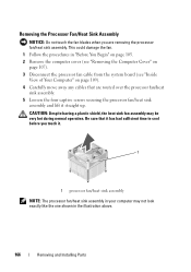
..."Before You Begin" on page 105. 2 Remove the computer cover (see "Removing the Computer Cover" on page 107). 3 Disconnect the processor fan cable from the system board (see "Inside View of Your Computer" on page 109). 4 Carefully move away any cables that it has ...had sufficient time to cool before you are routed over the processor fan/heat sink assembly. 5 Loosen the four captive screws securing the processor fan/heat sink assembly and lift it . 1 1 processor fan/heat sink assembly NOTE: The processor fan/heat sink assembly in the illustration above. 166 Removing and Installing Parts...
..."Before You Begin" on page 105. 2 Remove the computer cover (see "Removing the Computer Cover" on page 107). 3 Disconnect the processor fan cable from the system board (see "Inside View of Your Computer" on page 109). 4 Carefully move away any cables that it has ...had sufficient time to cool before you are routed over the processor fan/heat sink assembly. 5 Loosen the four captive screws securing the processor fan/heat sink assembly and lift it . 1 1 processor fan/heat sink assembly NOTE: The processor fan/heat sink assembly in the illustration above. 166 Removing and Installing Parts...
Owner's Manual
Page 167
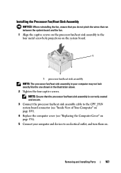
... that run between the system board and the fan. 1 Align the captive screws on the processor fan/heat sink assembly to an electrical outlet, and turn them on the system board. 1 1 processor fan/heat sink assembly NOTE: The processor fan/heat sink assembly in your computer and devices.... Removing and Installing Parts 167 Installing the Processor Fan/Heat Sink Assembly NOTICE: When reinstalling the fan, ensure that you do not pinch the wires that the processor fan/heat sink assembly is correctly seated and secure. 3 Connect the processor fan/heat sink assembly cable to the CPU_FAN system...
... that run between the system board and the fan. 1 Align the captive screws on the processor fan/heat sink assembly to an electrical outlet, and turn them on the system board. 1 1 processor fan/heat sink assembly NOTE: The processor fan/heat sink assembly in your computer and devices.... Removing and Installing Parts 167 Installing the Processor Fan/Heat Sink Assembly NOTICE: When reinstalling the fan, ensure that you do not pinch the wires that the processor fan/heat sink assembly is correctly seated and secure. 3 Connect the processor fan/heat sink assembly cable to the CPU_FAN system...

Owner's Manual
Page 168
... sufficient time to cool before you replace the processor. 168 Removing and Installing Parts CAUTION: Despite having a plastic shield, the heat sink assembly may be very hot during normal operation. Be sure that it . 3 Remove the processor fan/heat sink assembly from the computer (see ..."Removing the Computer Cover" on page 166). Removing the Processor 1 Follow the procedures in the Product Information Guide. Processor CAUTION: Before you begin any of the procedures in this ...
... sufficient time to cool before you replace the processor. 168 Removing and Installing Parts CAUTION: Despite having a plastic shield, the heat sink assembly may be very hot during normal operation. Be sure that it . 3 Remove the processor fan/heat sink assembly from the computer (see ..."Removing the Computer Cover" on page 166). Removing the Processor 1 Follow the procedures in the Product Information Guide. Processor CAUTION: Before you begin any of the procedures in this ...

Owner's Manual
Page 171
.... 12 Replace the computer cover (see "Installing the Processor Fan/Heat Sink Assembly" on page 176). 2 1 9 3 4 5 6 8 7 1 processor cover 2 tab 3 processor 4 processor socket 5 center cover latch 6 release lever 7 front alignment-notch 8 processor pin-1 indicator 9 rear alignment notch 9 Clean the thermal grease from the bottom of the processor. 11 Install the processor fan/heat sink assembly (see "Replacing the Computer Cover...
.... 12 Replace the computer cover (see "Installing the Processor Fan/Heat Sink Assembly" on page 176). 2 1 9 3 4 5 6 8 7 1 processor cover 2 tab 3 processor 4 processor socket 5 center cover latch 6 release lever 7 front alignment-notch 8 processor pin-1 indicator 9 rear alignment notch 9 Clean the thermal grease from the bottom of the processor. 11 Install the processor fan/heat sink assembly (see "Replacing the Computer Cover...


