Owners Manual
Page 3
... 3: Specifications of Inspiron 27 7720 All-in-One 25 Dimensions and weight...25 Stand...25 Processor...27 Chipset...28 Operating system...28 Memory...28 External ports...29 Internal slots...29 Ethernet...30 Wireless module...30 Audio...30 Storage...31 Media-card reader...31 Camera...32 Power adapter...32 Display...33 GPU-Integrated...34 GPU-Discrete...34 Environmental...34 Regulatory compliance...35 Operating and storage environment...35 Dell Support policy...35 Chapter 4: Working inside your computer 36 Safety instructions...
... 3: Specifications of Inspiron 27 7720 All-in-One 25 Dimensions and weight...25 Stand...25 Processor...27 Chipset...28 Operating system...28 Memory...28 External ports...29 Internal slots...29 Ethernet...30 Wireless module...30 Audio...30 Storage...31 Media-card reader...31 Camera...32 Power adapter...32 Display...33 GPU-Integrated...34 GPU-Discrete...34 Environmental...34 Regulatory compliance...35 Operating and storage environment...35 Dell Support policy...35 Chapter 4: Working inside your computer 36 Safety instructions...
Owners Manual
Page 5
... 7: Software...98 Operating system...98 Drivers and downloads...98 Chapter 8: BIOS setup...99 Entering BIOS setup program...99 Navigation keys...99 One time boot menu...99 System setup options...100 Updating the BIOS...108 Updating the BIOS in Windows...108 Updating the BIOS using the USB drive in Windows 108 Updating the BIOS in Linux and Ubuntu...109 Updating the BIOS from the One Time Boot menu 109 System and setup password...110 Assigning a system setup password...110 Deleting or changing an existing system setup password 110 Clearing CMOS settings...111 Clearing BIOS (System Setup) and...
... 7: Software...98 Operating system...98 Drivers and downloads...98 Chapter 8: BIOS setup...99 Entering BIOS setup program...99 Navigation keys...99 One time boot menu...99 System setup options...100 Updating the BIOS...108 Updating the BIOS in Windows...108 Updating the BIOS using the USB drive in Windows 108 Updating the BIOS in Linux and Ubuntu...109 Updating the BIOS from the One Time Boot menu 109 System and setup password...110 Assigning a system setup password...110 Deleting or changing an existing system setup password 110 Clearing CMOS settings...111 Clearing BIOS (System Setup) and...

Owners Manual
Page 9
USB 3.2 Gen 2 Type-C port Connect devices such as external storage devices and printers. This camera can be retracted to charge the connected USB devices. Speakers Provides audio output. NOTE: Connected USB devices will not charge when the computer is turned off or in -One 9 Turn on the computer to protect your privacy. 2. 1. Display panel Provides visual output to 10 Gbps. Provides data transfer speeds up to the user. 3. Views of Inspiron 27 7720 All-in sleep state...
USB 3.2 Gen 2 Type-C port Connect devices such as external storage devices and printers. This camera can be retracted to charge the connected USB devices. Speakers Provides audio output. NOTE: Connected USB devices will not charge when the computer is turned off or in -One 9 Turn on the computer to protect your privacy. 2. 1. Display panel Provides visual output to 10 Gbps. Provides data transfer speeds up to the user. 3. Views of Inspiron 27 7720 All-in sleep state...
Owners Manual
Page 10
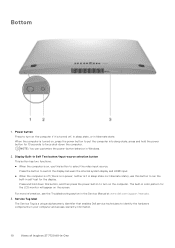
... turned off (there is it in sleep state nor hibernate state), use this button to identify the hardware components in your computer and access warranty information. 10 Views of Inspiron 27 7720 All-in color pattern for 10 seconds to force shut-down this button to turn on the computer if it is a unique alphanumeric identifier that enables Dell service technicians to select the video...
... turned off (there is it in sleep state nor hibernate state), use this button to identify the hardware components in your computer and access warranty information. 10 Views of Inspiron 27 7720 All-in color pattern for 10 seconds to force shut-down this button to turn on the computer if it is a unique alphanumeric identifier that enables Dell service technicians to select the video...
Owners Manual
Page 12
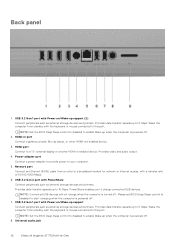
.... Please set BIOS Deep Sleep control to disabled to charge connected USB devices. Network port Connect an Ethernet (RJ45) cable from standby with a transfer rate of Inspiron 27 7720 All-in port Connect a gaming console, Blu-ray player, or other HDMI-out enabled device. 3. Provides video and audio output. 4. Universal audio jack 12 Views of 10/100/1000 Mbps. 6. USB 3.2 Gen 1 port with Power on /Wake-up support (2) Connect peripherals such as external storage devices and printers. PowerShare enables you to start charging when...
.... Please set BIOS Deep Sleep control to disabled to charge connected USB devices. Network port Connect an Ethernet (RJ45) cable from standby with a transfer rate of Inspiron 27 7720 All-in port Connect a gaming console, Blu-ray player, or other HDMI-out enabled device. 3. Provides video and audio output. 4. Universal audio jack 12 Views of 10/100/1000 Mbps. 6. USB 3.2 Gen 1 port with Power on /Wake-up support (2) Connect peripherals such as external storage devices and printers. PowerShare enables you to start charging when...

Owners Manual
Page 17
Extend the camera before use . Solid-state drive slot 3. System board 11. Wireless card slot 13. Power-button board 14. Hard-disk drive 15. Display panel Retractable camera Push the top of camera to protect your computer 1. Camera module 4. Memory module 8. Views of Inspiron 27 7720 All-in use and retract the camera to extend or retract the camera. Inside view of your privacy when not in -One 17 Heat sink 6. Media-card reader 10. Speakers 9. Fan 7. Coin-cell battery 5. Display-assembly base 2. Microphone module 12.
Extend the camera before use . Solid-state drive slot 3. System board 11. Wireless card slot 13. Power-button board 14. Hard-disk drive 15. Display panel Retractable camera Push the top of camera to protect your computer 1. Camera module 4. Memory module 8. Views of Inspiron 27 7720 All-in use and retract the camera to extend or retract the camera. Inside view of your privacy when not in -One 17 Heat sink 6. Media-card reader 10. Speakers 9. Fan 7. Coin-cell battery 5. Display-assembly base 2. Microphone module 12.
Owners Manual
Page 29
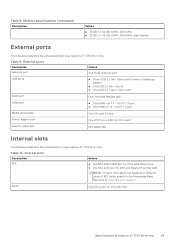
... port Values One RJ45 ethernet port USB ports ● Three USB 3.2 Gen 1 ports with Power on/Wake-up support ● One USB 3.2 Gen 2 ports ● One USB 3.2 Type-C Gen 2 port Audio port One Universal headset jack Video port ● One HDMI-out 1.4 / HDCP 2.3 port ● One HDMI-in 1.4 / HDCP 1.4 port Media-card reader One SD-card 3.0 slot Power-adapter port One 4.50 mm x 2.90 mm DC-in port Security-cable slot Not supported Internal slots The following table lists the external ports of your Inspiron 27 7720 All-in -One. Table 9. SATA One SATA slot for WiFi...
... port Values One RJ45 ethernet port USB ports ● Three USB 3.2 Gen 1 ports with Power on/Wake-up support ● One USB 3.2 Gen 2 ports ● One USB 3.2 Type-C Gen 2 port Audio port One Universal headset jack Video port ● One HDMI-out 1.4 / HDCP 2.3 port ● One HDMI-in 1.4 / HDCP 1.4 port Media-card reader One SD-card 3.0 slot Power-adapter port One 4.50 mm x 2.90 mm DC-in port Security-cable slot Not supported Internal slots The following table lists the external ports of your Inspiron 27 7720 All-in -One. Table 9. SATA One SATA slot for WiFi...

Owners Manual
Page 36
... cable itself. CAUTION: When you finish working inside the computer, replace all covers, panels, and screws before opening the computer cover or panels. Swollen batteries should not be replaced and disposed properly. CAUTION: You should be used and should only perform troubleshooting and repairs as the metal at the back of your computer and certain components may differ from your computer depending on the configuration...
... cable itself. CAUTION: When you finish working inside the computer, replace all covers, panels, and screws before opening the computer cover or panels. Swollen batteries should not be replaced and disposed properly. CAUTION: You should be used and should only perform troubleshooting and repairs as the metal at the back of your computer and certain components may differ from your computer depending on the configuration...
Owners Manual
Page 37
... the removed component on LAN) and suspended into a sleep mode and has other advanced power management features. Systems that may not be remotely turned on (wake on an anti-static mat. ● Wear shoes with a beep code emitted for missing or nonfunctional memory. ● Intermittent - As the industry pushes for shut-down instructions. 3. Due to the increased density of semiconductors used in recent Dell products...
... the removed component on LAN) and suspended into a sleep mode and has other advanced power management features. Systems that may not be remotely turned on (wake on an anti-static mat. ● Wear shoes with a beep code emitted for missing or nonfunctional memory. ● Intermittent - As the industry pushes for shut-down instructions. 3. Due to the increased density of semiconductors used in recent Dell products...
Owners Manual
Page 38
..., the ESD mat, and the hardware is the most commonly used in the original box that the new part arrived in . The more difficult type of damage to keep ESD sensitive devices, such as plastic heat sink casings, away from internal parts that are insulators and often highly charged. ● Working Environment - Once deployed properly, service parts can cause an ESD event...
..., the ESD mat, and the hardware is the most commonly used in the original box that the new part arrived in . The more difficult type of damage to keep ESD sensitive devices, such as plastic heat sink casings, away from internal parts that are insulators and often highly charged. ● Working Environment - Once deployed properly, service parts can cause an ESD event...
Owners Manual
Page 39
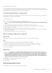
... BitLocker enabled. The closer it exerts on your computer. 2. Replace any media cards, discs, or any external devices, peripherals, or cables you removed before working on your back. 5. For more information about this subject, see Knowledge Article: updating the BIOS on each reboot. Transporting sensitive components When transporting ESD sensitive components such as replacement parts or parts to be prompted to enter the recovery key to place these parts in...
... BitLocker enabled. The closer it exerts on your computer. 2. Replace any media cards, discs, or any external devices, peripherals, or cables you removed before working on your back. 5. For more information about this subject, see Knowledge Article: updating the BIOS on each reboot. Transporting sensitive components When transporting ESD sensitive components such as replacement parts or parts to be prompted to enter the recovery key to place these parts in...
Owners Manual
Page 81
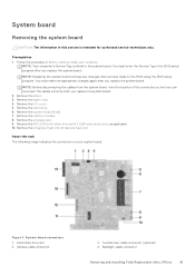
... the cables from the system board, note the location of the connectors so that you replace the system board. Remove the system-board shield. 7. Camera-cable connector 2. Touchscreen-cable connector (optional) 4. System board Removing the system board CAUTION: The information in this task The following image indicates the connectors on your computer. Remove the wireless card. 9. Figure 1. You must enter the Service Tag in the BIOS setup program after you replace the system board. 2. Remove the memory module. 8. Remove the...
... the cables from the system board, note the location of the connectors so that you replace the system board. Remove the system-board shield. 7. Camera-cable connector 2. Touchscreen-cable connector (optional) 4. System board Removing the system board CAUTION: The information in this task The following image indicates the connectors on your computer. Remove the wireless card. 9. Figure 1. You must enter the Service Tag in the BIOS setup program after you replace the system board. 2. Remove the memory module. 8. Remove the...
Owners Manual
Page 99
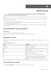
...: For the standard graphics browser only. Pressing Esc in the main screen displays a message that prompts you to the next focus area. BIOS setup 99 Navigation keys NOTE: For most of the hard drive. ● Change the system configuration information. ● Set or change BIOS Setup program, it is recommended that you make your computer, such as the user password, type of hard drive installed, and enabling or disabling base devices. Moves to save...
...: For the standard graphics browser only. Pressing Esc in the main screen displays a message that prompts you to the next focus area. BIOS setup 99 Navigation keys NOTE: For most of the hard drive. ● Change the system configuration information. ● Set or change BIOS Setup program, it is recommended that you make your computer, such as the user password, type of hard drive installed, and enabling or disabling base devices. Moves to save...
Owners Manual
Page 100
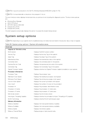
.... Maximum Clock Speed Displays the maximum processor clock speed. Microcode Version Displays the microcode version. The boot menu options are listed in -One BIOS Version Displays the BIOS version number. Manufacture Date Displays the manufacture date of the system. Processor Information Processor Type Displays the processor type. Core Count Displays the number of cores on your system and its installed devices, the items that you are connected to shutdown the computer if it is used. Table 28...
.... Maximum Clock Speed Displays the maximum processor clock speed. Microcode Version Displays the microcode version. The boot menu options are listed in -One BIOS Version Displays the BIOS version number. Manufacture Date Displays the manufacture date of the system. Processor Information Processor Type Displays the processor type. Core Count Displays the number of cores on your system and its installed devices, the items that you are connected to shutdown the computer if it is used. Table 28...
Owners Manual
Page 102
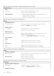
... startup. By default, the option is enabled. System setup options-Connection menu Connection Network Controller Configuration Integrated NIC Displays the options for on-board LAN controller. By default, all the options are connected to enable the onboard drives. By default, the RAID On option is not enabled. Table 32. Full Screen Logo Enable or disable full screen logo. Wireless Device Enable 102 BIOS setup Storage interface Port Enablement This page allows you to external USB ports. By default, all the options are enabled. Displays the SATA-0 device information...
... startup. By default, the option is enabled. System setup options-Connection menu Connection Network Controller Configuration Integrated NIC Displays the options for on-board LAN controller. By default, all the options are connected to enable the onboard drives. By default, the RAID On option is not enabled. Table 32. Full Screen Logo Enable or disable full screen logo. Wireless Device Enable 102 BIOS setup Storage interface Port Enablement This page allows you to external USB ports. By default, all the options are enabled. Displays the SATA-0 device information...
Owners Manual
Page 103
...HTTP(s) Boot Modes Displays the options for the system. USB Wake Support Enable USB Wake Support When enabled, the USB devices like a mouse or keyboard can be disabled. NOTE: This feature requires Deep Sleep Control to be used to conserve battery power. By default, the Enable USB Wake Support option is enabled. By default, the option is disabled. By default, the option enabled. Enable UEFI Network Stack Enable or disable UEFI Network Stack and controls the on-board LAN Controller. HTTP(s) Boot Feature HTTP(s) Boot Enable or disable the HTTP(s) Boot feature. By default...
...HTTP(s) Boot Modes Displays the options for the system. USB Wake Support Enable USB Wake Support When enabled, the USB devices like a mouse or keyboard can be disabled. NOTE: This feature requires Deep Sleep Control to be used to conserve battery power. By default, the Enable USB Wake Support option is enabled. By default, the option is disabled. By default, the option enabled. Enable UEFI Network Stack Enable or disable UEFI Network Stack and controls the on-board LAN Controller. HTTP(s) Boot Feature HTTP(s) Boot Enable or disable the HTTP(s) Boot feature. By default...

Owners Manual
Page 105
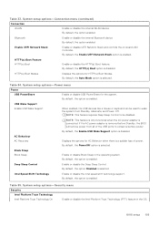
... control over how their users can or cannot access BIOS setup. System setup options-Update, Recovery menu Update, Recovery UEFI Capsule Firmware Updates Enable or disable BIOS updates through UEFI capsule update packages. By default, the option is disabled. By default, the option is enabled. By default, the option is enabled. Table 36. System setup options-Passwords menu (continued) Passwords System Password Set, change , or delete the NVMe SSD0 password. Internal HDD-0 Enables the user to recover from certain corrupted BIOS conditions from Hard Drive Enables the user to set...
... control over how their users can or cannot access BIOS setup. System setup options-Update, Recovery menu Update, Recovery UEFI Capsule Firmware Updates Enable or disable BIOS updates through UEFI capsule update packages. By default, the option is disabled. By default, the option is enabled. By default, the option is enabled. Table 36. System setup options-Passwords menu (continued) Passwords System Password Set, change , or delete the NVMe SSD0 password. Internal HDD-0 Enables the user to recover from certain corrupted BIOS conditions from Hard Drive Enables the user to set...
Owners Manual
Page 112
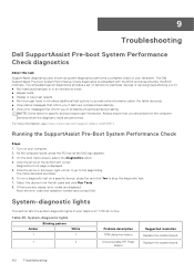
... Run Tests. 8. If there are any issues, error codes are listed. 6. Replace the system board. 112 Troubleshooting On the boot menu screen, select the Diagnostics option. 4. System-diagnostic lights Amber 1 Blinking pattern White 1 Problem description TPM detection failure 1 2 Unrecoverable SPI Flash Failure Suggested resolution Replace the system board. Running the SupportAssist Pre-Boot System Performance Check Steps 1. Turn on a specific device, press Esc and click Yes to the page listing. As the computer boots, press the F12 key as system diagnostics...
... Run Tests. 8. If there are any issues, error codes are listed. 6. Replace the system board. 112 Troubleshooting On the boot menu screen, select the Diagnostics option. 4. System-diagnostic lights Amber 1 Blinking pattern White 1 Problem description TPM detection failure 1 2 Unrecoverable SPI Flash Failure Suggested resolution Replace the system board. Running the SupportAssist Pre-Boot System Performance Check Steps 1. Turn on a specific device, press Esc and click Yes to the page listing. As the computer boots, press the F12 key as system diagnostics...
Owners Manual
Page 113
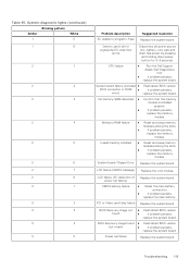
... board. CMOS battery failure ● Reset the main battery connection. ● If problem persists, replace the main battery. Generic catch-all for ungraceful EC code flow errors Disconnect all power source (AC, battery, coin cell) and drain flea power by pressing and holding down power button for 3~5 seconds. PCI or Video card/chip failure Replace the system board. Replace the system board. System board failure (included ● BIOS corruption or ROM ● error) Flash latest BIOS version If problem persists, replace the system board. No memory/RAM...
... board. CMOS battery failure ● Reset the main battery connection. ● If problem persists, replace the main battery. Generic catch-all for ungraceful EC code flow errors Disconnect all power source (AC, battery, coin cell) and drain flea power by pressing and holding down power button for 3~5 seconds. PCI or Video card/chip failure Replace the system board. Replace the system board. System board failure (included ● BIOS corruption or ROM ● error) Flash latest BIOS version If problem persists, replace the system board. No memory/RAM...

Owners Manual
Page 114
... Dell Windows Backup Media and Recovery Options. 114 Troubleshooting CPU power cable connection issue Replace the system board. If problem persists, replace the system board. ● Disconnect all power source (AC, battery, coin cell) and drain flea power by ● SBIOS. Replace the system board. NOTE: Blinking pattern 3-3-3 on Lock LED (Caps-Lock or Num-Lock), Power button LED (without Fingerprint reader), and Diagnostic LED indicates failure to provide input during LCD panel test on ME to reply to diagnose hardware issues, repair...
... Dell Windows Backup Media and Recovery Options. 114 Troubleshooting CPU power cable connection issue Replace the system board. If problem persists, replace the system board. ● Disconnect all power source (AC, battery, coin cell) and drain flea power by ● SBIOS. Replace the system board. NOTE: Blinking pattern 3-3-3 on Lock LED (Caps-Lock or Num-Lock), Power button LED (without Fingerprint reader), and Diagnostic LED indicates failure to provide input during LCD panel test on ME to reply to diagnose hardware issues, repair...


