
Inspiron 24 5000 Service Manual
Page 5
Removing the heat sink 39 Prerequisites 39 Procedure 39 Replacing the heat sink 41 Procedure 41 Post-requisites 41 Removing the fan 42 Prerequisites 42 Procedure 42 Replacing the fan 44 Procedure 44 Post-requisites 44 Removing the coin-cell battery 45 Prerequisites 45 Procedure 45 Replacing the coin-cell battery 47 Procedure 47 Post-requisites 47 Removing the processor 48 Prerequisites 48 Procedure 48 Replacing the processor 50 Procedure 50 Post-requisites 51 5
Removing the heat sink 39 Prerequisites 39 Procedure 39 Replacing the heat sink 41 Procedure 41 Post-requisites 41 Removing the fan 42 Prerequisites 42 Procedure 42 Replacing the fan 44 Procedure 44 Post-requisites 44 Removing the coin-cell battery 45 Prerequisites 45 Procedure 45 Replacing the coin-cell battery 47 Procedure 47 Post-requisites 47 Removing the processor 48 Prerequisites 48 Procedure 48 Replacing the processor 50 Procedure 50 Post-requisites 51 5

Inspiron 24 5000 Service Manual
Page 11
....5 1 Hard-drive assembly Middle-frame M3x5 1 base Hard-drive bracket Hard drive M3x3.5 3 Wireless-card bracket Wireless card M2x2.5 1 Heat sink Middle-frame M3x5 1 base Fan Middle-frame M3x5 2 base VESA-mount bracket Middle-frame M3x5 4 base System board Middle-frame M3x5 5 base Speaker cover Middle-frame M3x3 4 base Middle-frame...
....5 1 Hard-drive assembly Middle-frame M3x5 1 base Hard-drive bracket Hard drive M3x3.5 3 Wireless-card bracket Wireless card M2x2.5 1 Heat sink Middle-frame M3x5 1 base Fan Middle-frame M3x5 2 base VESA-mount bracket Middle-frame M3x5 4 base System board Middle-frame M3x5 5 base Speaker cover Middle-frame M3x3 4 base Middle-frame...

Inspiron 24 5000 Service Manual
Page 15
7 right microphone (touch-screen models only) 9 fan 11 heat sink 13 memory modules 15 system board 8 camera 10 left microphone (touch-screen models only) 12 wireless card 14 coin-cell battery GUID-10780793-CEA7-4C74-9763-8F42F335BD8B System-board components 1 display-backlight cable connector 2 control-buttons board cable connector 3 display-cable connector 4 hard-drive data cable connector 15
7 right microphone (touch-screen models only) 9 fan 11 heat sink 13 memory modules 15 system board 8 camera 10 left microphone (touch-screen models only) 12 wireless card 14 coin-cell battery GUID-10780793-CEA7-4C74-9763-8F42F335BD8B System-board components 1 display-backlight cable connector 2 control-buttons board cable connector 3 display-cable connector 4 hard-drive data cable connector 15

Inspiron 24 5000 Service Manual
Page 16
5 optical-drive data cable connector 6 hard-drive and optical-drive power cable connector 7 touch-screen board cable connector 8 fan-cable connector 9 processor socket 10 wireless-card slot 11 memory-module slots (2) 12 camera and microphone-cable connector 13 CMOS jumper 14 password jumper 15 speaker-cable connector 16
5 optical-drive data cable connector 6 hard-drive and optical-drive power cable connector 7 touch-screen board cable connector 8 fan-cable connector 9 processor socket 10 wireless-card slot 11 memory-module slots (2) 12 camera and microphone-cable connector 13 CMOS jumper 14 password jumper 15 speaker-cable connector 16

Inspiron 24 5000 Service Manual
Page 42
For more safety best practices, see the Regulatory Compliance home page at www.dell.com/ regulatory_compliance. GUID-3781B0E2-638C-41D1-8401-8D8D6F7B4F03 Procedure 1 Disconnect the fan cable from the system board. 2 Remove the two screws (M3x5) that shipped with your computer and follow the ...instructions in Before working inside your computer. GUID-FAA962E5-AD4D-4E85-BCA3-D99993D9AFD2 Removing the fan WARNING: Before working inside your computer, read the safety information that secure the fan to the middle-frame base. 42 After working inside your computer, follow the steps in...
For more safety best practices, see the Regulatory Compliance home page at www.dell.com/ regulatory_compliance. GUID-3781B0E2-638C-41D1-8401-8D8D6F7B4F03 Procedure 1 Disconnect the fan cable from the system board. 2 Remove the two screws (M3x5) that shipped with your computer and follow the ...instructions in Before working inside your computer. GUID-FAA962E5-AD4D-4E85-BCA3-D99993D9AFD2 Removing the fan WARNING: Before working inside your computer, read the safety information that secure the fan to the middle-frame base. 42 After working inside your computer, follow the steps in...

Inspiron 24 5000 Service Manual
Page 43
3 Lift the fan off the middle-frame base. 1 fan cable 3 middle-frame base 2 M3x5 screws (2) 4 fan 43
3 Lift the fan off the middle-frame base. 1 fan cable 3 middle-frame base 2 M3x5 screws (2) 4 fan 43

Inspiron 24 5000 Service Manual
Page 44
...Align the screw holes on the middle-frame base. 2 Replace the two screws (M3x5) that shipped with the screw holes on the fan with your computer and follow the instructions in Before working inside your computer. GUID-2596AFC0-F1E8-4A0E-A603-7D2CFE582ECE Replacing the... working inside your computer, read the safety information that secure the fan to the middle-frame base. 3 Connect the fan cable to the system board. For more safety best practices, see the Regulatory Compliance home page at www.dell.com/ regulatory_compliance. GUID-17536558-648A-4BF5-A4F5-814B0AA01A44 Post-requisites 1...
...Align the screw holes on the middle-frame base. 2 Replace the two screws (M3x5) that shipped with the screw holes on the fan with your computer and follow the instructions in Before working inside your computer. GUID-2596AFC0-F1E8-4A0E-A603-7D2CFE582ECE Replacing the... working inside your computer, read the safety information that secure the fan to the middle-frame base. 3 Connect the fan cable to the system board. For more safety best practices, see the Regulatory Compliance home page at www.dell.com/ regulatory_compliance. GUID-17536558-648A-4BF5-A4F5-814B0AA01A44 Post-requisites 1...

Inspiron 24 5000 Service Manual
Page 71
GUID-B767856A-17BF-416D-A92F-3B6EC306BDAC Procedure 1 Disconnect the speaker, camera and microphone, and fan cables from the system board. 1 speaker cable 3 fan cable 2 camera and microphone cable 2 Disconnect the display-backlight, optical-drive data, hard-drive data, hard-drive and optical-drive power, and touch-screen board cables from the system board. 71
GUID-B767856A-17BF-416D-A92F-3B6EC306BDAC Procedure 1 Disconnect the speaker, camera and microphone, and fan cables from the system board. 1 speaker cable 3 fan cable 2 camera and microphone cable 2 Disconnect the display-backlight, optical-drive data, hard-drive data, hard-drive and optical-drive power, and touch-screen board cables from the system board. 71
Inspiron 24 5000 Service Manual
Page 74
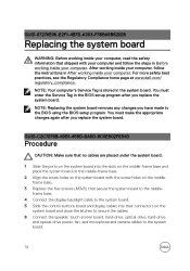
... enter the Service Tag in After working inside your computer. For more safety best practices, see the Regulatory Compliance home page at www.dell.com/ regulatory_compliance. NOTE: Your computer's Service Tag is stored in Before working inside your computer. NOTE: Replacing the system board removes ... to secure the cables. 6 Connect the speaker, touch-screen board, hard-drive, optical-drive, hard-drive and optical-drive power, fan, and microphone and camera cables to the BIOS using the BIOS setup program. GUID-67274E98-E2F1-4B7B-A903-F38BA6B62028 Replacing the system board WARNING...
... enter the Service Tag in After working inside your computer. For more safety best practices, see the Regulatory Compliance home page at www.dell.com/ regulatory_compliance. NOTE: Your computer's Service Tag is stored in Before working inside your computer. NOTE: Replacing the system board removes ... to secure the cables. 6 Connect the speaker, touch-screen board, hard-drive, optical-drive, hard-drive and optical-drive power, fan, and microphone and camera cables to the BIOS using the BIOS setup program. GUID-67274E98-E2F1-4B7B-A903-F38BA6B62028 Replacing the system board WARNING...

Inspiron 24 5000 Service Manual
Page 76
... 1 Remove the stand. 2 Remove the back cover. 3 Remove the optical drive. 4 Remove the hard drive. 5 Remove the wireless card. 6 Remove the heat sink. 7 Remove the fan. 8 Remove the system board. 9 Remove the VESA-mount bracket. 10 Remove the speaker cover. After working inside your computer, follow the steps in After working... your computer and follow the instructions in Before working inside your computer. For more safety best practices, see the Regulatory Compliance home page at www.dell.com/ regulatory_compliance.
... 1 Remove the stand. 2 Remove the back cover. 3 Remove the optical drive. 4 Remove the hard drive. 5 Remove the wireless card. 6 Remove the heat sink. 7 Remove the fan. 8 Remove the system board. 9 Remove the VESA-mount bracket. 10 Remove the speaker cover. After working inside your computer, follow the steps in After working... your computer and follow the instructions in Before working inside your computer. For more safety best practices, see the Regulatory Compliance home page at www.dell.com/ regulatory_compliance.

Inspiron 24 5000 Service Manual
Page 82
3 Replace the system board. 4 Replace the fan. 5 Replace the heat sink. 6 Replace the wireless card. 7 Replace the hard drive. 8 Replace the optical drive. 9 Replace the back cover. 10 Replace the stand. 82
3 Replace the system board. 4 Replace the fan. 5 Replace the heat sink. 6 Replace the wireless card. 7 Replace the hard drive. 8 Replace the optical drive. 9 Replace the back cover. 10 Replace the stand. 82

Inspiron 24 5000 Service Manual
Page 83
For more safety best practices, see the Regulatory Compliance home page at www.dell.com/ regulatory_compliance. GUID-552E75E5-5CA2-4286-8A48-3906C8A9A066 Procedure 1 Remove the two screws (M3x5) that shipped with your computer and follow the instructions in Before ... 1 Remove the stand. 2 Remove the back cover. 3 Remove the optical drive. 4 Remove the hard drive. 5 Remove the wireless card. 6 Remove the heat sink. 7 Remove the fan. 8 Remove the system board. 9 Remove the VESA-mount bracket. 10 Remove the speaker cover. 11 Remove the middle-frame base. GUID-19CE5907-7DCB-4B1B-9B38...
For more safety best practices, see the Regulatory Compliance home page at www.dell.com/ regulatory_compliance. GUID-552E75E5-5CA2-4286-8A48-3906C8A9A066 Procedure 1 Remove the two screws (M3x5) that shipped with your computer and follow the instructions in Before ... 1 Remove the stand. 2 Remove the back cover. 3 Remove the optical drive. 4 Remove the hard drive. 5 Remove the wireless card. 6 Remove the heat sink. 7 Remove the fan. 8 Remove the system board. 9 Remove the VESA-mount bracket. 10 Remove the speaker cover. 11 Remove the middle-frame base. GUID-19CE5907-7DCB-4B1B-9B38...

Inspiron 24 5000 Service Manual
Page 85
..., follow the steps in After working inside your computer. For more safety best practices, see the Regulatory Compliance home page at www.dell.com/ regulatory_compliance. GUID-915F0249-50CC-4B0D-A654-B832E90956CD Procedure 1 Align the screw holes on the rubber foot with the screw holes on... Post-requisites 1 Replace the middle-frame base. 2 Replace the speaker cover. 3 Replace the VESA-mount bracket. 4 Replace the system board. 5 Replace the fan. 6 Replace the heat sink. 7 Replace the wireless card. 8 Replace the hard drive. 9 Replace the optical drive. 10 Replace the back cover. 11...
..., follow the steps in After working inside your computer. For more safety best practices, see the Regulatory Compliance home page at www.dell.com/ regulatory_compliance. GUID-915F0249-50CC-4B0D-A654-B832E90956CD Procedure 1 Align the screw holes on the rubber foot with the screw holes on... Post-requisites 1 Replace the middle-frame base. 2 Replace the speaker cover. 3 Replace the VESA-mount bracket. 4 Replace the system board. 5 Replace the fan. 6 Replace the heat sink. 7 Replace the wireless card. 8 Replace the hard drive. 9 Replace the optical drive. 10 Replace the back cover. 11...

Inspiron 24 5000 Service Manual
Page 86
..., see the Regulatory Compliance home page at www.dell.com/ regulatory_compliance. GUID-098385CD-39BA-4A51-8FE8-4FA4FD342AB3 Prerequisites 1 Remove the stand. 2 Remove the back cover. 3 Remove the optical drive. 4 Remove the hard drive. 5 Remove the wireless card. 6 Remove the heat sink. 7 Remove the fan. 8 Remove the microphone. 9 Follow the procedure from step...
..., see the Regulatory Compliance home page at www.dell.com/ regulatory_compliance. GUID-098385CD-39BA-4A51-8FE8-4FA4FD342AB3 Prerequisites 1 Remove the stand. 2 Remove the back cover. 3 Remove the optical drive. 4 Remove the hard drive. 5 Remove the wireless card. 6 Remove the heat sink. 7 Remove the fan. 8 Remove the microphone. 9 Follow the procedure from step...

Inspiron 24 5000 Service Manual
Page 88
For more safety best practices, see the Regulatory Compliance home page at www.dell.com/ regulatory_compliance. GUID-E993FB19-54F7-4DDD-8B55-503462373D1D Post-requisites 1 Replace the rubber feet. 2 Replace the middle-frame base. 3 Replace the control-buttons board. 4 Replace ... the VESA-mount bracket. 7 Replace the system board. 8 Follow the procedure from step 2 to step 5 in "Replacing the camera". 9 Replace the microphone. 10 Replace the fan. 11 Replace the heat sink. 12 Replace the wireless card. 13 Replace the hard drive. 14 Replace the optical drive. 88 GUID-FBEC17A1-151D-4CCA...
For more safety best practices, see the Regulatory Compliance home page at www.dell.com/ regulatory_compliance. GUID-E993FB19-54F7-4DDD-8B55-503462373D1D Post-requisites 1 Replace the rubber feet. 2 Replace the middle-frame base. 3 Replace the control-buttons board. 4 Replace ... the VESA-mount bracket. 7 Replace the system board. 8 Follow the procedure from step 2 to step 5 in "Replacing the camera". 9 Replace the microphone. 10 Replace the fan. 11 Replace the heat sink. 12 Replace the wireless card. 13 Replace the hard drive. 14 Replace the optical drive. 88 GUID-FBEC17A1-151D-4CCA...


