
Owners Manual
Page 9
... cables, network cables, and attached devices from their electrical outlets. 4 Disconnect all open the Charms sidebar, and then click Settings→ Power→ Shut down on a soft and clean surface to avoid scratching the display. 6 Place the computer face down . NOTE: If you turn off your computer. 1 Save and close all open files and exit all open programs before you are using...
... cables, network cables, and attached devices from their electrical outlets. 4 Disconnect all open the Charms sidebar, and then click Settings→ Power→ Shut down on a soft and clean surface to avoid scratching the display. 6 Place the computer face down . NOTE: If you turn off your computer. 1 Save and close all open files and exit all open programs before you are using...
Owners Manual
Page 10
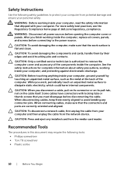
... dell.com/regulatory_compliance. When connecting cables, make sure that the connectors and ports are correctly oriented and aligned. WARNING: Before working inside your computer, read the safety information that shipped with locking tabs or thumb-screws that you finish working inside the computer, replace all power sources before connecting to remove the computer cover and access any of the computer. WARNING: Disconnect all covers, panels, and screws before opening...
... dell.com/regulatory_compliance. When connecting cables, make sure that the connectors and ports are correctly oriented and aligned. WARNING: Before working inside your computer, read the safety information that shipped with locking tabs or thumb-screws that you finish working inside the computer, replace all power sources before connecting to remove the computer cover and access any of the computer. WARNING: Disconnect all covers, panels, and screws before opening...

Owners Manual
Page 11
After Working Inside Your Computer CAUTION: Leaving stray or loose screws inside your computer may severely damage your computer. 1 Replace all screws and make sure that no stray screws remain inside your computer. 2 Place the computer in an upright position. 3 Connect any external devices, cables, cards, and any other part(s) you removed before working on your computer. 4 Connect your computer and all attached devices to their electrical outlets. After Working Inside Your Computer | 11
After Working Inside Your Computer CAUTION: Leaving stray or loose screws inside your computer may severely damage your computer. 1 Replace all screws and make sure that no stray screws remain inside your computer. 2 Place the computer in an upright position. 3 Connect any external devices, cables, cards, and any other part(s) you removed before working on your computer. 4 Connect your computer and all attached devices to their electrical outlets. After Working Inside Your Computer | 11

Owners Manual
Page 20
... and follow the instructions in "Before You Begin" on page 9. Postrequisites Replace the base cover. See "Replacing the Base Cover" on page 11. Replacing the Computer Base WARNING: Before working inside your computer, read the safety information that secure the computer base to the stand assembly. 4 Connect the display cables to the system board. 5 Connect the antenna cables to the wireless mini-card. For more safety...
... and follow the instructions in "Before You Begin" on page 9. Postrequisites Replace the base cover. See "Replacing the Base Cover" on page 11. Replacing the Computer Base WARNING: Before working inside your computer, read the safety information that secure the computer base to the stand assembly. 4 Connect the display cables to the system board. 5 Connect the antenna cables to the wireless mini-card. For more safety...
Owners Manual
Page 21
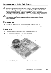
... steps in "After Working Inside Your Computer" on page 9. CAUTION: Removing the coin-cell battery resets the BIOS settings to default. It is recommended that shipped with its cable, off the coin-cell battery from the system board. 3 Lift the coin-cell battery, along with your computer and follow the instructions in "Before You Begin" on page 11. See "Removing the Base Cover" on page...
... steps in "After Working Inside Your Computer" on page 9. CAUTION: Removing the coin-cell battery resets the BIOS settings to default. It is recommended that shipped with its cable, off the coin-cell battery from the system board. 3 Lift the coin-cell battery, along with your computer and follow the instructions in "Before You Begin" on page 11. See "Removing the Base Cover" on page...

Owners Manual
Page 24
5 Remove the screws that secure the hard-drive bracket to the hard drive. 6 Lift the hard-drive assembly off the hard-drive bracket. 7 Remove the interposer from the hard drive. 1 2 3 4 1 hard drive 3 interposer 2 screws (4) 4 hard-drive bracket 24 | Removing the Hard Drive
5 Remove the screws that secure the hard-drive bracket to the hard drive. 6 Lift the hard-drive assembly off the hard-drive bracket. 7 Remove the interposer from the hard drive. 1 2 3 4 1 hard drive 3 interposer 2 screws (4) 4 hard-drive bracket 24 | Removing the Hard Drive

Owners Manual
Page 25
... system board. Postrequisites 1 Replace the computer base. CAUTION: Hard drives are fragile. For more safety best practices, see the Regulatory Compliance home page at dell.com/regulatory_compliance. Replacing the Hard Drive WARNING: Before working inside your computer, read the safety information that secure the hard-drive assembly to the computer base. 7 Route the speaker cable through the routing guides on the hard-drive assembly. 8 Connect the speaker cable to the hard-drive...
... system board. Postrequisites 1 Replace the computer base. CAUTION: Hard drives are fragile. For more safety best practices, see the Regulatory Compliance home page at dell.com/regulatory_compliance. Replacing the Hard Drive WARNING: Before working inside your computer, read the safety information that secure the hard-drive assembly to the computer base. 7 Route the speaker cable through the routing guides on the hard-drive assembly. 8 Connect the speaker cable to the hard-drive...

Owners Manual
Page 27
... page at dell.com/regulatory_compliance. See "Replacing the Computer Base" on page 17. Replacing the USB board WARNING: Before working inside your computer, read the safety information that secures the USB board to the computer base. 3 Connect the USB-board cable to the connector on the USB board. 4 Follow step 5 to step 8 in "Replacing the Hard Drive" on page 25. Postrequisites 1 Replace the computer base. See "Replacing the Base Cover" on page...
... page at dell.com/regulatory_compliance. See "Replacing the Computer Base" on page 17. Replacing the USB board WARNING: Before working inside your computer, read the safety information that secures the USB board to the computer base. 3 Connect the USB-board cable to the connector on the USB board. 4 Follow step 5 to step 8 in "Replacing the Hard Drive" on page 25. Postrequisites 1 Replace the computer base. See "Replacing the Base Cover" on page...
Owners Manual
Page 29
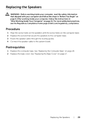
... Speakers WARNING: Before working inside your computer, read the safety information that secure the speakers to the computer base. 3 Route the speaker cable through the routing guides. 4 Connect the speaker cable to the system board. Replacing the Speakers | 29 After working inside your computer and follow the instructions in "Before You Begin" on page 9. For more safety best practices, see the Regulatory Compliance home page at dell...
... Speakers WARNING: Before working inside your computer, read the safety information that secure the speakers to the computer base. 3 Route the speaker cable through the routing guides. 4 Connect the speaker cable to the system board. Replacing the Speakers | 29 After working inside your computer and follow the instructions in "Before You Begin" on page 9. For more safety best practices, see the Regulatory Compliance home page at dell...
Owners Manual
Page 40
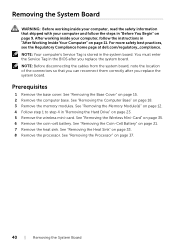
... 33. 8 Remove the processor. See "Removing the Processor" on page 23. 5 Remove the wireless mini-card. NOTE: Before disconnecting the cables from the system board, note the location of the connectors so that shipped with your computer, follow the steps in the system board. You must enter the Service Tag in "Removing the Hard Drive" on page 37. 40 | Removing the System Board Prerequisites 1 Remove the base cover. See "Removing the Memory Module(s)" on...
... 33. 8 Remove the processor. See "Removing the Processor" on page 23. 5 Remove the wireless mini-card. NOTE: Before disconnecting the cables from the system board, note the location of the connectors so that shipped with your computer, follow the steps in the system board. You must enter the Service Tag in "Removing the Hard Drive" on page 37. 40 | Removing the System Board Prerequisites 1 Remove the base cover. See "Removing the Memory Module(s)" on...
Owners Manual
Page 42
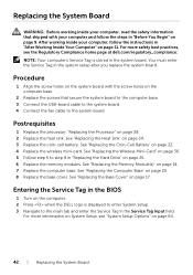
... follow the instructions in "After Working Inside Your Computer" on page 22. 4 Replace the wireless mini-card. See "Replacing the Wireless Mini-Card" on page 36. 5 Follow step 5 to step 8 in "Replacing the Hard Drive" on the computer. 2 Press when the DELL logo is stored in the system setup after you replace the system board. Entering the Service Tag in the BIOS 1 Turn on page 25. 6 Replace the memory modules. After working inside your...
... follow the instructions in "After Working Inside Your Computer" on page 22. 4 Replace the wireless mini-card. See "Replacing the Wireless Mini-Card" on page 36. 5 Follow step 5 to step 8 in "Replacing the Hard Drive" on the computer. 2 Press when the DELL logo is stored in the system setup after you replace the system board. Entering the Service Tag in the BIOS 1 Turn on page 25. 6 Replace the memory modules. After working inside your...
Owners Manual
Page 63
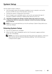
... make any changes. Entering System Setup 1 Turn on . System Setup Use the system setup to utility to: • Get information about the hardware installed on your computer, such as the amount of RAM, the size of the hard drive, and so on. • Change the system configuration information. • Set or change a user-selectable option, such as the user password, type of hard drive installed, enabling or disabling base devices, and so on (or restart) your computer. 2 When the DELL...
... make any changes. Entering System Setup 1 Turn on . System Setup Use the system setup to utility to: • Get information about the hardware installed on your computer, such as the amount of RAM, the size of the hard drive, and so on. • Change the system configuration information. • Set or change a user-selectable option, such as the user password, type of hard drive installed, enabling or disabling base devices, and so on (or restart) your computer. 2 When the DELL...
Owners Manual
Page 64
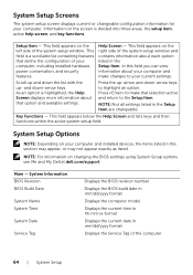
... system setup window. Scroll up and down the list with the up -arrow and down -arrow keys. Press to make changes to your computer and make that option and available settings. System Setup Screens The system setup screen displays current or changeable configuration information for your computer and installed devices, the items listed in the Setup Item are changeable. Information on changing the BIOS settings using System Setup options see Me and My Dell at dell.com/support...
... system setup window. Scroll up and down the list with the up -arrow and down -arrow keys. Press to make changes to your computer and make that option and available settings. System Setup Screens The system setup screen displays current or changeable configuration information for your computer and installed devices, the items listed in the Setup Item are changeable. Information on changing the BIOS settings using System Setup options see Me and My Dell at dell.com/support...
Owners Manual
Page 65
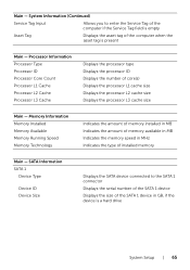
... to the SATA 1 connector Displays the serial number of the SATA 1 device Displays the size of the SATA 1 device in MHz Indicates the type of the computer when the asset tag is a hard drive System Setup | 65 SATA Information SATA 1 Device Type Device ID Device Size Displays the SATA device connected to enter the Service Tag of the computer if the Service Tag field is empty Asset Tag Displays the asset tag of installed memory Main - Memory Information Memory Installed Memory Available Memory Running Speed Memory Technology Indicates...
... to the SATA 1 connector Displays the serial number of the SATA 1 device Displays the size of the SATA 1 device in MHz Indicates the type of the computer when the asset tag is a hard drive System Setup | 65 SATA Information SATA 1 Device Type Device ID Device Size Displays the SATA device connected to enter the Service Tag of the computer if the Service Tag field is empty Asset Tag Displays the asset tag of installed memory Main - Memory Information Memory Installed Memory Available Memory Running Speed Memory Technology Indicates...
Owners Manual
Page 66
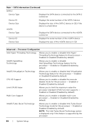
... the processor - Enabled or Disabled (Enabled by default) CPU XD Support Allows you to enable or disable Intel HyperThreading Technology feature for the processor - Enabled or Disabled (Enabled by default) NOTE: The Intel Turbo Boost Technology option is displayed only if this feature is a hard drive mSATA Device Type Displays the SATA device connected to the mSATA connector Device ID Displays the serial number of the mSATA device Device Size Displays the size of the SATA 2 device in GB, if the device is supported by default) Intel...
... the processor - Enabled or Disabled (Enabled by default) CPU XD Support Allows you to enable or disable Intel HyperThreading Technology feature for the processor - Enabled or Disabled (Enabled by default) NOTE: The Intel Turbo Boost Technology option is displayed only if this feature is a hard drive mSATA Device Type Displays the SATA device connected to the mSATA connector Device ID Displays the serial number of the mSATA device Device Size Displays the size of the SATA 2 device in GB, if the device is supported by default) Intel...
Owners Manual
Page 67
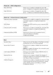
... as hard drive, optical drive, USB key, and so on your computer (ATA by default) Onboard LAN Controller Allows you to enable or disable the onboard LAN controller Enabled or Disabled (Enabled by default) Onboard LAN Boot ROM Allows you to boot your computer from a network Enabled or Disabled (Disabled by default) Boot Numlock Key Secure Boot Control Load Legacy OPROM Keyboard Errors USB Boot Support Allows you to enable or disable the secure boot control NOTE: To enable this feature, the computer must be in the UEFI boot mode. Onboard Device Configuration Onboard Audio Controller...
... as hard drive, optical drive, USB key, and so on your computer (ATA by default) Onboard LAN Controller Allows you to enable or disable the onboard LAN controller Enabled or Disabled (Enabled by default) Onboard LAN Boot ROM Allows you to boot your computer from a network Enabled or Disabled (Disabled by default) Boot Numlock Key Secure Boot Control Load Legacy OPROM Keyboard Errors USB Boot Support Allows you to enable or disable the secure boot control NOTE: To enable this feature, the computer must be in the UEFI boot mode. Onboard Device Configuration Onboard Audio Controller...
Owners Manual
Page 68
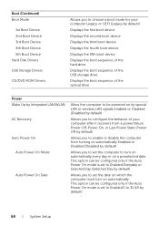
...) Boot Mode 1st Boot Device 2nd Boot Device 3rd Boot Device 4th Boot Device 5th Boot Device Hard Disk Drivers USB Storage Drivers CD/DVD ROM Drivers Allows you to choose a boot mode for your computer Legacy or UEFI (Legacy by default) Displays the first boot device Displays the second boot device Displays the third boot device Displays the fourth boot device Displays the fifth boot device Displays the boot sequence of the hard drive Displays the boot sequence of the USB storage drive Displays the boot sequence of the optical drive Power Wake Up by Integrated LAN/WLAN AC Recovery Auto Power...
...) Boot Mode 1st Boot Device 2nd Boot Device 3rd Boot Device 4th Boot Device 5th Boot Device Hard Disk Drivers USB Storage Drivers CD/DVD ROM Drivers Allows you to choose a boot mode for your computer Legacy or UEFI (Legacy by default) Displays the first boot device Displays the second boot device Displays the third boot device Displays the fourth boot device Displays the fifth boot device Displays the boot sequence of the hard drive Displays the boot sequence of the USB storage drive Displays the boot sequence of the optical drive Power Wake Up by Integrated LAN/WLAN AC Recovery Auto Power...
Owners Manual
Page 70
... 15. 6 Connect the USB-board cable to the system board. Exit Save Changes and Reset Discard Changes and Reset Load Defaults Allows you to exit system setup and save your changes Allows you to exit system setup and load previous values for all system setup options Allows you to load default values for approximately five seconds to clear the CMOS settings. 4 Connect the coin-cell battery cable to the system board. 5 Replace the base cover.
... 15. 6 Connect the USB-board cable to the system board. Exit Save Changes and Reset Discard Changes and Reset Load Defaults Allows you to exit system setup and save your changes Allows you to exit system setup and load previous values for all system setup options Allows you to load default values for approximately five seconds to clear the CMOS settings. 4 Connect the coin-cell battery cable to the system board. 5 Replace the base cover.
Owners Manual
Page 71
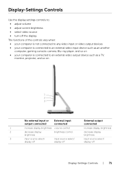
Display-Settings Controls Use the display settings controls to: • adjust volume • adjust screen brightness • select video source • turn off the display The functions of the controls vary when: • your computer is not connected to any video input or video output devices • your computer is connected to an external video input device such as an another computer, gaming console, camera, Blu-ray player, and so on...
Display-Settings Controls Use the display settings controls to: • adjust volume • adjust screen brightness • select video source • turn off the display The functions of the controls vary when: • your computer is not connected to any video input or video output devices • your computer is connected to an external video input device such as an another computer, gaming console, camera, Blu-ray player, and so on...

Owners Manual
Page 72
... display brightness. • Display off: Press and hold to turn off button and the power button simultaneously to initialize display diagnostics. Brightness Touch to an external video output device. The display settings controls provide an on-screen display (OSD) when your computer is disabled in Windows 8 charms. Input source select Touch to switch between video input sources. NOTE: Brightness control feature is connected to access the brightness controls menu. Touch to close the OSD controls. 72 | Display-Settings Controls...
... display brightness. • Display off: Press and hold to turn off button and the power button simultaneously to initialize display diagnostics. Brightness Touch to an external video output device. The display settings controls provide an on-screen display (OSD) when your computer is disabled in Windows 8 charms. Input source select Touch to switch between video input sources. NOTE: Brightness control feature is connected to access the brightness controls menu. Touch to close the OSD controls. 72 | Display-Settings Controls...


