Service Manual
Page 3
Contents 1 Before You Begin 9 Recommended Tools 9 Turning Off Your Computer 9 Before Working Inside Your Computer 10 2 Top Cover 13 Removing the Top Cover 13 Replacing the Top Cover 14 3 Battery 15 Removing the Battery 15 Replacing the Battery 16 4 Module Cover 17 Removing the Module Cover 17 Replacing the Module Cover 18 5 Optical Drive 19 Removing the Optical Drive 19 Contents 3
Contents 1 Before You Begin 9 Recommended Tools 9 Turning Off Your Computer 9 Before Working Inside Your Computer 10 2 Top Cover 13 Removing the Top Cover 13 Replacing the Top Cover 14 3 Battery 15 Removing the Battery 15 Replacing the Battery 16 4 Module Cover 17 Removing the Module Cover 17 Replacing the Module Cover 18 5 Optical Drive 19 Removing the Optical Drive 19 Contents 3

Service Manual
Page 6
Removing the Display Brackets 62 Replacing the Display Brackets 63 14 Camera Module 65 Removing the Camera Module 65 Replacing the Camera Module 66 15 Hinge Cover 69 Removing the Hinge Cover 69 Replacing the Hinge Cover 71 16 VGA Connector Board 73 Removing the VGA Connector Board 73 Replacing the VGA Connector Board 74 17 System Board 77 Removing the System Board 77 Replacing the System Board 81 Entering the Service Tag in the BIOS 82 18 Speakers 83 Removing the Speakers 83 Replacing the Speakers 84 6 Contents
Removing the Display Brackets 62 Replacing the Display Brackets 63 14 Camera Module 65 Removing the Camera Module 65 Replacing the Camera Module 66 15 Hinge Cover 69 Removing the Hinge Cover 69 Replacing the Hinge Cover 71 16 VGA Connector Board 73 Removing the VGA Connector Board 73 Replacing the VGA Connector Board 74 17 System Board 77 Removing the System Board 77 Replacing the System Board 81 Entering the Service Tag in the BIOS 82 18 Speakers 83 Removing the Speakers 83 Replacing the Speakers 84 6 Contents

Service Manual
Page 14
... computer, replace all screws and ensure that no gaps between the top cover and display back cover. CAUTION: Before turning on page 9. Ensure that the Dell logo is facing towards the back of the computer while replacing the top cover. 2 Align the top cover to the display back cover. 3 Slide the...
... computer, replace all screws and ensure that no gaps between the top cover and display back cover. CAUTION: Before turning on page 9. Ensure that the Dell logo is facing towards the back of the computer while replacing the top cover. 2 Align the top cover to the display back cover. 3 Slide the...

Service Manual
Page 58
1 1 display bezel Replacing the Display Bezel 1 Follow the instructions in "Before You Begin" on page 14). Display Panel Removing the Display Panel 1 Follow the instructions in "Before You Begin" on page 9. 2 Realign the display bezel over the display panel and gently snap it into place. 3 Replace the display assembly (see "Replacing the Display Assembly" on page 56). 4 Replace the top cover (see "Replacing the Top Cover" on page 9. 58 Display
1 1 display bezel Replacing the Display Bezel 1 Follow the instructions in "Before You Begin" on page 14). Display Panel Removing the Display Panel 1 Follow the instructions in "Before You Begin" on page 9. 2 Realign the display bezel over the display panel and gently snap it into place. 3 Replace the display assembly (see "Replacing the Display Assembly" on page 56). 4 Replace the top cover (see "Replacing the Top Cover" on page 9. 58 Display

Service Manual
Page 65
... and remove the tape that secures the camera cable to servicing that shipped with your warranty. 14 Camera Module WARNING: Before working inside your computer, read the safety information that is not authorized by Dell is not covered by periodically touching an unpainted metal surface (such as a connector on your... working inside the computer. CAUTION: To help prevent damage to the system board, remove the main battery (see the Regulatory Compliance Homepage at dell.com/regulatory_compliance. CAUTION: Only a certified service technician should perform repairs on your computer.
... and remove the tape that secures the camera cable to servicing that shipped with your warranty. 14 Camera Module WARNING: Before working inside your computer, read the safety information that is not authorized by Dell is not covered by periodically touching an unpainted metal surface (such as a connector on your... working inside the computer. CAUTION: To help prevent damage to the system board, remove the main battery (see the Regulatory Compliance Homepage at dell.com/regulatory_compliance. CAUTION: Only a certified service technician should perform repairs on your computer.
Service Manual
Page 79
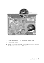
System Board 79 1 2 3 1 display cable connector 3 speakers cable connector 2 display cable grounding screw 14 Lift the system board assembly to disconnect the connector on the system board from the connector on the I/O board.
System Board 79 1 2 3 1 display cable connector 3 speakers cable connector 2 display cable grounding screw 14 Lift the system board assembly to disconnect the connector on the system board from the connector on the I/O board.
Service Manual
Page 81
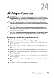
... thermal fan (see "Replacing the Thermal Fan" on page 50). 13 Replace the palm-rest assembly (see "Replacing the Palm-Rest Assembly" on page 35). 14 Replace the keyboard (see "Replacing the Keyboard" on page 29). 15 Connect the AC-adapter connector cable to the connector on the system board. 16...
... thermal fan (see "Replacing the Thermal Fan" on page 50). 13 Replace the palm-rest assembly (see "Replacing the Palm-Rest Assembly" on page 35). 14 Replace the keyboard (see "Replacing the Keyboard" on page 29). 15 Connect the AC-adapter connector cable to the connector on the system board. 16...

Service Manual
Page 83
... system board, remove the main battery (see the Regulatory Compliance Homepage at dell.com/regulatory_compliance. CAUTION: To help prevent damage to servicing that shipped with the its cable from step 2 to step 14 in "Removing the System Board" on your computer. Speakers 83 CAUTION: To... before working inside the computer. 18 Speakers WARNING: Before working inside your computer, read the safety information that is not authorized by Dell is not covered by periodically touching an unpainted metal surface (such as a connector on page 77. 3 Note the speakers cable routing...
... system board, remove the main battery (see the Regulatory Compliance Homepage at dell.com/regulatory_compliance. CAUTION: To help prevent damage to servicing that shipped with the its cable from step 2 to step 14 in "Removing the System Board" on your computer. Speakers 83 CAUTION: To... before working inside the computer. 18 Speakers WARNING: Before working inside your computer, read the safety information that is not authorized by Dell is not covered by periodically touching an unpainted metal surface (such as a connector on page 77. 3 Note the speakers cable routing...

Service Manual
Page 99
... 6 Remove the two screws that secure the I/O board to the computer base. 7 Lift the I/O board off the computer base. Damage due to step 14 in "Removing the System Board" on page 77. 3 Remove the Mini-Card(s) (see "Removing the Mini-Card(s)" on page 45). 4 Remove the display...I/O Board 1 Follow the instructions in "Before You Begin" on page 9. 2 Follow the instructions from step 2 to servicing that is not authorized by Dell is not covered by periodically touching an unpainted metal surface (such as a connector on your computer). 23 I/O Board WARNING: Before working inside your computer, ...
... 6 Remove the two screws that secure the I/O board to the computer base. 7 Lift the I/O board off the computer base. Damage due to step 14 in "Removing the System Board" on page 77. 3 Remove the Mini-Card(s) (see "Removing the Mini-Card(s)" on page 45). 4 Remove the display...I/O Board 1 Follow the instructions in "Before You Begin" on page 9. 2 Follow the instructions from step 2 to servicing that is not authorized by Dell is not covered by periodically touching an unpainted metal surface (such as a connector on your computer). 23 I/O Board WARNING: Before working inside your computer, ...
Service Manual
Page 101
...the instructions in "Before You Begin" on page 9. 2 Follow the instructions from the routing guides. 7 Remove the screw that is not authorized by Dell is not covered by periodically touching an unpainted metal surface (such as a connector on page 73). 6 Note the AC-adapter connector cable routing and ...remove the cable from step 2 to step 14 in "Removing the System Board" on page 77. 3 Remove the display assembly (see "Removing the Display Assembly" on page 53). 4 Remove the hinge...
...the instructions in "Before You Begin" on page 9. 2 Follow the instructions from the routing guides. 7 Remove the screw that is not authorized by Dell is not covered by periodically touching an unpainted metal surface (such as a connector on page 73). 6 Note the AC-adapter connector cable routing and ...remove the cable from step 2 to step 14 in "Removing the System Board" on page 77. 3 Remove the display assembly (see "Removing the Display Assembly" on page 53). 4 Remove the hinge...
Setup Guide
Page 5
... System 9 Create System Recovery Media (Recommended 10 Install the SIM Card (Optional 12 Enable or Disable Wireless (Optional 14 Set Up Wireless Display (Optional 16 Connect to the Internet (Optional 18 Using Your Inspiron Laptop 22 Right View Features 22 Left View Features 24 Back View Features 28 Front View Features... Using the Optical Drive 42 Display Features 44 Removing and Replacing the Top Cover (Optional 46 Removing and Replacing the Battery 50 Software Features 52 Dell DataSafe Online Backup 53...
... System 9 Create System Recovery Media (Recommended 10 Install the SIM Card (Optional 12 Enable or Disable Wireless (Optional 14 Set Up Wireless Display (Optional 16 Connect to the Internet (Optional 18 Using Your Inspiron Laptop 22 Right View Features 22 Left View Features 24 Back View Features 28 Front View Features... Using the Optical Drive 42 Display Features 44 Removing and Replacing the Top Cover (Optional 46 Removing and Replacing the Battery 50 Software Features 52 Dell DataSafe Online Backup 53...

Setup Guide
Page 16
Setting Up Your Inspiron Laptop Enable or Disable Wireless (Optional) 14
Setting Up Your Inspiron Laptop Enable or Disable Wireless (Optional) 14

Setup Guide
Page 21
...to a wireless router: 1. Follow the instructions on the screen to a network. 5. Save and close any open files, and exit any open programs. 3. Setting Up Your Inspiron Laptop Setting Up a Wireless Connection NOTE: To set up your wireless router, see "Enable or Disable Wireless (Optional)" on page... 14). 2. Before you can help you do not have a service outage. To set up your computer (see the documentation that wireless is enabled on your ...
...to a wireless router: 1. Follow the instructions on the screen to a network. 5. Save and close any open files, and exit any open programs. 3. Setting Up Your Inspiron Laptop Setting Up a Wireless Connection NOTE: To set up your wireless router, see "Enable or Disable Wireless (Optional)" on page... 14). 2. Before you can help you do not have a service outage. To set up your computer (see the documentation that wireless is enabled on your ...
Setup Guide
Page 33
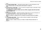
... CAUTION: To avoid loss of data, never turn off the computer when the hard drive activity light is enabled. Turns on page 14". 31 Indicates the power states. Indicates the battery charge status. A solid white light indicates that wireless is powered using the AC ...4 Wireless status light - NOTE: To enable or disable wireless, see "Status Lights and Indicators" on . 3 Battery status light - Using Your Inspiron Laptop 1 Power indicator light - For more information on the battery status light, see "Enable or Disable Wireless (Optional)" on when the computer reads...
... CAUTION: To avoid loss of data, never turn off the computer when the hard drive activity light is enabled. Turns on page 14". 31 Indicates the power states. Indicates the battery charge status. A solid white light indicates that wireless is powered using the AC ...4 Wireless status light - NOTE: To enable or disable wireless, see "Status Lights and Indicators" on . 3 Battery status light - Using Your Inspiron Laptop 1 Power indicator light - For more information on the battery status light, see "Enable or Disable Wireless (Optional)" on when the computer reads...
Setup Guide
Page 59
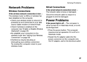
... button. Try moving the computer closer to the wireless router (see "Enable or Disable Wireless (Optional)" on the computer, into the power connector on page 14). • Re-establish your connection to your wireless connection. The computer is plugged in hibernate mode. • Reseat the AC adapter cable into the AC...
... button. Try moving the computer closer to the wireless router (see "Enable or Disable Wireless (Optional)" on the computer, into the power connector on page 14). • Re-establish your connection to your wireless connection. The computer is plugged in hibernate mode. • Reseat the AC adapter cable into the AC...

Setup Guide
Page 92
Specifications Display Type Dimensions: Height Width Diagonal Maximum resolution Refresh rate 14.0-inch HD WLED TrueLife 309.40 mm (12.18 inches) 173.95 mm (6.85 inches) 355.60 mm (14.00 inches) 1366 x 768 60 Hz Display Operating angle 0° (closed) to 135° Horizontal viewing angle Vertical viewing angle Pixel pitch 40/40 15/30 (H/L) 0.226 mm x 0.226 mm Touch Pad X/Y position resolution (graphics table mode) Size: Height Width 240 cpi 44.00 mm (1.73 inches) 82.00 mm (3.23 inches) 90
Specifications Display Type Dimensions: Height Width Diagonal Maximum resolution Refresh rate 14.0-inch HD WLED TrueLife 309.40 mm (12.18 inches) 173.95 mm (6.85 inches) 355.60 mm (14.00 inches) 1366 x 768 60 Hz Display Operating angle 0° (closed) to 135° Horizontal viewing angle Vertical viewing angle Pixel pitch 40/40 15/30 (H/L) 0.226 mm x 0.226 mm Touch Pad X/Y position resolution (graphics table mode) Size: Height Width 240 cpi 44.00 mm (1.73 inches) 82.00 mm (3.23 inches) 90

Setup Guide
Page 100
Index Program Compatibility Wizard 60 Windows Mobility Center 40 wired network network cable, connecting 7 problems 57 wireless network connecting 14 problems 57 98
Index Program Compatibility Wizard 60 Windows Mobility Center 40 wired network network cable, connecting 7 problems 57 wireless network connecting 14 problems 57 98


