Service Manual
Page 3
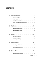
Contents 1 Before You Begin 9 Recommended Tools 9 Turning Off Your Computer 9 Before Working Inside Your Computer 10 2 Top Cover 13 Removing the Top Cover 13 Replacing the Top Cover 14 3 Battery 15 Removing the Battery 15 Replacing the Battery 16 4 Module Cover 17 Removing the Module Cover 17 Replacing the Module Cover 18 5 Optical Drive 19 Removing the Optical Drive 19 Contents 3
Contents 1 Before You Begin 9 Recommended Tools 9 Turning Off Your Computer 9 Before Working Inside Your Computer 10 2 Top Cover 13 Removing the Top Cover 13 Replacing the Top Cover 14 3 Battery 15 Removing the Battery 15 Replacing the Battery 16 4 Module Cover 17 Removing the Module Cover 17 Replacing the Module Cover 18 5 Optical Drive 19 Removing the Optical Drive 19 Contents 3
Service Manual
Page 9
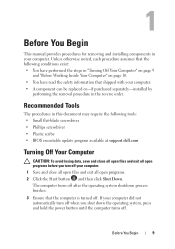
...and "Before Working Inside Your Computer" on page 10. • You have read the safety information that the computer is turned off . Before You Begin 9 The computer turns off after the operating system shutdown process finishes. 3 Ensure that shipped with your computer. • A component can be...tools: • Small flat-blade screwdriver • Phillips screwdriver • Plastic scribe • BIOS executable update program available at support.dell.com Turning Off Your Computer CAUTION: To avoid losing data, save and close all open files and exit all open programs. 2 Click the ...
...and "Before Working Inside Your Computer" on page 10. • You have read the safety information that the computer is turned off . Before You Begin 9 The computer turns off after the operating system shutdown process finishes. 3 Ensure that shipped with your computer. • A component can be...tools: • Small flat-blade screwdriver • Phillips screwdriver • Plastic scribe • BIOS executable update program available at support.dell.com Turning Off Your Computer CAUTION: To avoid losing data, save and close all open files and exit all open programs. 2 Click the ...

Service Manual
Page 10
... cards from the 8-in on your computer). Damage due to prevent the computer cover from being scratched. 2 Turn off your computer (see the Regulatory Compliance Homepage at dell.com/regulatory_compliance. CAUTION: To avoid electrostatic discharge, ground yourself by using a wrist grounding strap or by its...electrical outlets. 6 Disconnect all attached devices. WARNING: Before working inside your computer, read the safety information that is not authorized by Dell is not covered by its pull-tab, not on page 9) and all attached devices from your computer. 10 Before You Begin ...
... cards from the 8-in on your computer). Damage due to prevent the computer cover from being scratched. 2 Turn off your computer (see the Regulatory Compliance Homepage at dell.com/regulatory_compliance. CAUTION: To avoid electrostatic discharge, ground yourself by using a wrist grounding strap or by its...electrical outlets. 6 Disconnect all attached devices. WARNING: Before working inside your computer, read the safety information that is not authorized by Dell is not covered by its pull-tab, not on page 9) and all attached devices from your computer. 10 Before You Begin ...

Service Manual
Page 11
CAUTION: To help prevent damage to the system board, remove the main battery (see "Removing the Battery" on page 15) before working inside the computer. 7 Remove the battery (see "Removing the Battery" on page 15). 8 Turn the computer top-side up, open the display, and press the power button to ground the system board. Before You Begin 11
CAUTION: To help prevent damage to the system board, remove the main battery (see "Removing the Battery" on page 15) before working inside the computer. 7 Remove the battery (see "Removing the Battery" on page 15). 8 Turn the computer top-side up, open the display, and press the power button to ground the system board. Before You Begin 11

Service Manual
Page 14
... cover. Ensure that there are no stray screws remain inside the computer. CAUTION: Before turning on page 9. Failure to do so may result in "Before You Begin" on the computer, replace all screws and ensure that the Dell logo is facing towards the back of the computer while replacing the top cover...
... cover. Ensure that there are no stray screws remain inside the computer. CAUTION: Before turning on page 9. Failure to do so may result in "Before You Begin" on the computer, replace all screws and ensure that the Dell logo is facing towards the back of the computer while replacing the top cover...

Service Manual
Page 15
..."Before You Begin" on your computer. Damage due to servicing that shipped with your computer. Do not use only the battery designed for other Dell computers. Battery 15 CAUTION: To avoid damage to the unlock position. 5 Slide and lift the battery out of the battery bay. CAUTION: ...Only a certified service technician should perform repairs on page 9. 2 Shut down the computer and turn it over. 3 Slide the battery lock latch until it clicks into place. 4 Slide the battery release latch to the computer, use batteries designed for...
..."Before You Begin" on your computer. Damage due to servicing that shipped with your computer. Do not use only the battery designed for other Dell computers. Battery 15 CAUTION: To avoid damage to the unlock position. 5 Slide and lift the battery out of the battery bay. CAUTION: ...Only a certified service technician should perform repairs on page 9. 2 Shut down the computer and turn it over. 3 Slide the battery lock latch until it clicks into place. 4 Slide the battery release latch to the computer, use batteries designed for...
Service Manual
Page 18
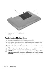
CAUTION: Before turning on the computer, replace all screws and ensure that secures the module cover to the computer base. 4 Replace the battery (see "Replacing the Battery" on page 16). Failure to do so may result in place. 3 Tighten the captive screw that no stray screws remain inside the computer. 1 2 3 1 captive screw 2 module cover 3 tabs (2) Replacing the Module Cover 1 Follow the instructions in "Before You Begin" on page 9. 2 Align the tabs on the module cover with the slots on the computer base and gently snap the cover in damage to the computer. 18 Module Cover
CAUTION: Before turning on the computer, replace all screws and ensure that secures the module cover to the computer base. 4 Replace the battery (see "Replacing the Battery" on page 16). Failure to do so may result in place. 3 Tighten the captive screw that no stray screws remain inside the computer. 1 2 3 1 captive screw 2 module cover 3 tabs (2) Replacing the Module Cover 1 Follow the instructions in "Before You Begin" on page 9. 2 Align the tabs on the module cover with the slots on the computer base and gently snap the cover in damage to the computer. 18 Module Cover
Service Manual
Page 21
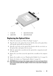
Optical Drive 21 CAUTION: Before turning on the computer, replace all screws and ensure that secures the optical-drive assembly to the computer. Failure to do so may result in "Before ...
Optical Drive 21 CAUTION: Before turning on the computer, replace all screws and ensure that secures the optical-drive assembly to the computer. Failure to do so may result in "Before ...
Service Manual
Page 25
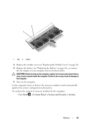
Memory 25 To confirm the amount of memory installed in damage to your computer and an electrical outlet. CAUTION: Before turning on the computer. As the computer boots, it detects the memory module(s) and automatically updates the system configuration information. Failure to do so may result ... "Replacing the Module Cover" on page 18). 5 Replace the battery (see "Replacing the Battery" on page 16), or connect the AC adapter to the computer. 6 Turn on the computer, replace all screws and ensure that no stray screws remain inside the computer.
Memory 25 To confirm the amount of memory installed in damage to your computer and an electrical outlet. CAUTION: Before turning on the computer. As the computer boots, it detects the memory module(s) and automatically updates the system configuration information. Failure to do so may result ... "Replacing the Module Cover" on page 18). 5 Replace the battery (see "Replacing the Battery" on page 16), or connect the AC adapter to the computer. 6 Turn on the computer, replace all screws and ensure that no stray screws remain inside the computer.
Service Manual
Page 27
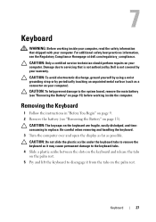
... to the system board, remove the main battery (see the Regulatory Compliance Homepage at dell.com/regulatory_compliance. CAUTION: The keycaps on your computer. Be careful when removing and handling the keyboard. 3 Turn the computer over and open the display as far as a connector on page 15)... before working inside the computer. 7 Keyboard WARNING: Before working inside your computer, read the safety information that is not authorized by Dell is not covered by periodically...
... to the system board, remove the main battery (see the Regulatory Compliance Homepage at dell.com/regulatory_compliance. CAUTION: The keycaps on your computer. Be careful when removing and handling the keyboard. 3 Turn the computer over and open the display as far as a connector on page 15)... before working inside the computer. 7 Keyboard WARNING: Before working inside your computer, read the safety information that is not authorized by Dell is not covered by periodically...
Service Manual
Page 28
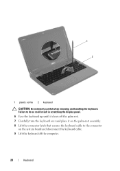
1 2 1 plastic scribe 2 keyboard CAUTION: Be extremely careful when removing and handling the keyboard. Failure to do so could result in scratching the display panel. 6 Ease the keyboard up until it clears off the palm rest. 7 Carefully turn the keyboard over and place it on the palm-rest assembly. 8 Lift the connector latch that secures the keyboard cable to the connector on the system board and disconnect the keyboard cable. 9 Lift the keyboard off the computer. 28 Keyboard
1 2 1 plastic scribe 2 keyboard CAUTION: Be extremely careful when removing and handling the keyboard. Failure to do so could result in scratching the display panel. 6 Ease the keyboard up until it clears off the palm rest. 7 Carefully turn the keyboard over and place it on the palm-rest assembly. 8 Lift the connector latch that secures the keyboard cable to the connector on the system board and disconnect the keyboard cable. 9 Lift the keyboard off the computer. 28 Keyboard
Service Manual
Page 29
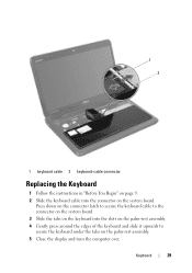
Press down on the connector latch to secure the keyboard cable to secure the keyboard under the tabs on the system board. Keyboard 29 1 2 1 keyboard cable 2 keyboard-cable connector Replacing the Keyboard 1 Follow the instructions in "Before You Begin" on page 9. 2 Slide the keyboard cable into the slots on the palm-rest assembly. 4 Gently press around the edges of the keyboard and slide it upwards to the connector on the system board. 3 Slide the tabs on the keyboard into the connector on the palm-rest assembly. 5 Close the display and turn the computer over.
Press down on the connector latch to secure the keyboard cable to secure the keyboard under the tabs on the system board. Keyboard 29 1 2 1 keyboard cable 2 keyboard-cable connector Replacing the Keyboard 1 Follow the instructions in "Before You Begin" on page 9. 2 Slide the keyboard cable into the slots on the palm-rest assembly. 4 Gently press around the edges of the keyboard and slide it upwards to the connector on the system board. 3 Slide the tabs on the keyboard into the connector on the palm-rest assembly. 5 Close the display and turn the computer over.

Service Manual
Page 34
CAUTION: Carefully separate the palm rest from the computer base to avoid damage to the palm rest. 9 Using a plastic scribe, carefully pry out the palm-rest assembly along the rear edge and then ease the palm-rest assembly from the computer base. 10 Lift the palm-rest assembly off the computer base. 11 Turn the palm-rest assembly over. 12 Remove the hot-key board (see "Removing the Hot-Key Board" on page 37). 13 Remove the power button board (see "Removing the Power Button Board" on page 41). 1 2 1 plastic scribe 2 palm-rest assembly 34 Palm-Rest Assembly
CAUTION: Carefully separate the palm rest from the computer base to avoid damage to the palm rest. 9 Using a plastic scribe, carefully pry out the palm-rest assembly along the rear edge and then ease the palm-rest assembly from the computer base. 10 Lift the palm-rest assembly off the computer base. 11 Turn the palm-rest assembly over. 12 Remove the hot-key board (see "Removing the Hot-Key Board" on page 37). 13 Remove the power button board (see "Removing the Power Button Board" on page 41). 1 2 1 plastic scribe 2 palm-rest assembly 34 Palm-Rest Assembly

Service Manual
Page 35
Failure to the computer. CAUTION: Before turning on page 16). Palm-Rest Assembly 35 Replacing the Palm-Rest Assembly 1 Follow the instructions in "Before You Begin" on page 9. 2 Replace the power button ... the connector latches to secure them. 6 Replace the five screws on the palm-rest assembly. 7 Replace the keyboard (see "Replacing the Keyboard" on page 29). 8 Turn the computer over and replace the ten screws at the bottom of the computer. 9 Follow the instructions from step 4 to step 5 in damage to do...
Failure to the computer. CAUTION: Before turning on page 16). Palm-Rest Assembly 35 Replacing the Palm-Rest Assembly 1 Follow the instructions in "Before You Begin" on page 9. 2 Replace the power button ... the connector latches to secure them. 6 Replace the five screws on the palm-rest assembly. 7 Replace the keyboard (see "Replacing the Keyboard" on page 29). 8 Turn the computer over and replace the ten screws at the bottom of the computer. 9 Follow the instructions from step 4 to step 5 in damage to do...
Service Manual
Page 37
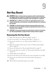
... keyboard (see "Removing the Keyboard" on page 27). 6 Remove the palm-rest assembly (see "Removing the Palm-Rest Assembly" on page 31). 7 Turn the palm-rest assembly over. 8 Remove the hot-key board cable from the slot on page 15) before working inside the computer. 9 Hot-Key Board... WARNING: Before working inside your computer, read the safety information that is not authorized by Dell is not covered by periodically touching an unpainted metal surface (such as a connector on your computer). Damage due to the palm-rest assembly. ...
... keyboard (see "Removing the Keyboard" on page 27). 6 Remove the palm-rest assembly (see "Removing the Palm-Rest Assembly" on page 31). 7 Turn the palm-rest assembly over. 8 Remove the hot-key board cable from the slot on page 15) before working inside the computer. 9 Hot-Key Board... WARNING: Before working inside your computer, read the safety information that is not authorized by Dell is not covered by periodically touching an unpainted metal surface (such as a connector on your computer). Damage due to the palm-rest assembly. ...
Service Manual
Page 38
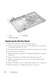
rest assembly and replace the screw. 3 Route the hot-key board cable through the slot on the palm-rest assembly. 4 Turn the palm-rest assembly over. 5 Replace the palm-rest assembly (see "Replacing the Palm-Rest Assembly" on page 35). 6 Replace the keyboard (see "Replacing the ...
rest assembly and replace the screw. 3 Route the hot-key board cable through the slot on the palm-rest assembly. 4 Turn the palm-rest assembly over. 5 Replace the palm-rest assembly (see "Replacing the Palm-Rest Assembly" on page 35). 6 Replace the keyboard (see "Replacing the ...
Service Manual
Page 39
Hot-Key Board 39 Failure to do so may result in damage to the computer. CAUTION: Before turning on the computer, replace all screws and ensure that no stray screws remain inside the computer.
Hot-Key Board 39 Failure to do so may result in damage to the computer. CAUTION: Before turning on the computer, replace all screws and ensure that no stray screws remain inside the computer.
Service Manual
Page 41
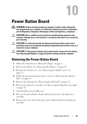
... avoid electrostatic discharge, ground yourself by using a wrist grounding strap or by your warranty. Damage due to servicing that is not authorized by Dell is not covered by periodically touching an unpainted metal surface (such as a connector on the palm-rest assembly. 9 Remove the screw that... shipped with your computer. For additional safety best practices information, see "Removing the Palm-Rest Assembly" on page 31). 7 Turn the palm-rest assembly over. 8 Remove the power-button board cable from step 4 to step 5 in "Before You Begin" on page 9. 2 Remove...
... avoid electrostatic discharge, ground yourself by using a wrist grounding strap or by your warranty. Damage due to servicing that is not authorized by Dell is not covered by periodically touching an unpainted metal surface (such as a connector on the palm-rest assembly. 9 Remove the screw that... shipped with your computer. For additional safety best practices information, see "Removing the Palm-Rest Assembly" on page 31). 7 Turn the palm-rest assembly over. 8 Remove the power-button board cable from step 4 to step 5 in "Before You Begin" on page 9. 2 Remove...
Service Manual
Page 42
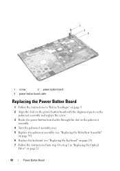
... alignment posts on the palm-rest assembly and replace the screw. 3 Route the power-button board cable through the slot on the palm-rest assembly. 4 Turn the palm-rest assembly over. 5 Replace the palm-rest assembly (see "Replacing the Palm-Rest Assembly" on page 35). 6 Replace the keyboard (see "Replacing the...
... alignment posts on the palm-rest assembly and replace the screw. 3 Route the power-button board cable through the slot on the palm-rest assembly. 4 Turn the palm-rest assembly over. 5 Replace the palm-rest assembly (see "Replacing the Palm-Rest Assembly" on page 35). 6 Replace the keyboard (see "Replacing the...
Service Manual
Page 43
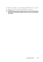
Failure to do so may result in damage to the computer. 8 Replace the module cover (see "Replacing the Module Cover" on page 18). 9 Replace the battery (see "Removing the Battery" on the computer, replace all screws and ensure that no stray screws remain inside the computer. CAUTION: Before turning on page 15). Power Button Board 43
Failure to do so may result in damage to the computer. 8 Replace the module cover (see "Replacing the Module Cover" on page 18). 9 Replace the battery (see "Removing the Battery" on the computer, replace all screws and ensure that no stray screws remain inside the computer. CAUTION: Before turning on page 15). Power Button Board 43


