Service Manual
Page 3
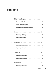
Contents 1 Before You Begin 9 Recommended Tools 9 Turning Off Your Computer 9 Before Working Inside Your Computer 10 2 Battery 13 Removing the Battery 13 Replacing the Battery 14 3 Hinge Cover 15 Removing the Hinge Cover 15 Replacing the Hinge Cover 16 4 Keyboard 17 Removing the Keyboard 17 Replacing the Keyboard 19 5 Hard Drive 21 Removing the Hard Drive 22 Contents 3
Contents 1 Before You Begin 9 Recommended Tools 9 Turning Off Your Computer 9 Before Working Inside Your Computer 10 2 Battery 13 Removing the Battery 13 Replacing the Battery 14 3 Hinge Cover 15 Removing the Hinge Cover 15 Replacing the Hinge Cover 16 4 Keyboard 17 Removing the Keyboard 17 Replacing the Keyboard 19 5 Hard Drive 21 Removing the Hard Drive 22 Contents 3
Service Manual
Page 17
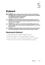
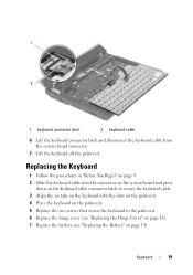
...4 Remove the two screws that secure the keyboard to the system board, remove the main battery (see the Regulatory Compliance Homepage at www.dell.com/regulatory_compliance. CAUTION: To help prevent damage to the palm rest. 5 Keyboard WARNING: Before working inside your computer, read ...the safety information that is not authorized by Dell™ is not covered by periodically touching ...
...4 Remove the two screws that secure the keyboard to the system board, remove the main battery (see the Regulatory Compliance Homepage at www.dell.com/regulatory_compliance. CAUTION: To help prevent damage to the palm rest. 5 Keyboard WARNING: Before working inside your computer, read ...the safety information that is not authorized by Dell™ is not covered by periodically touching ...
Service Manual
Page 18
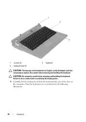
CAUTION: Be extremely careful when removing and handling the keyboard. Be careful when removing and handling the keyboard. Turn the keyboard over as indicated in scratching the display panel. 5 Carefully lift the keyboard and slide the keyboard tabs out of the slots on the keyboard are fragile, easily dislodged, and timeconsuming to replace. 1 2 3 1 screws (2) 3 keyboard tabs (4) 2 keyboard CAUTION: The keycaps on the computer. Failure to do so could result in the following illustration. 18 Keyboard
CAUTION: Be extremely careful when removing and handling the keyboard. Be careful when removing and handling the keyboard. Turn the keyboard over as indicated in scratching the display panel. 5 Carefully lift the keyboard and slide the keyboard tabs out of the slots on the keyboard are fragile, easily dislodged, and timeconsuming to replace. 1 2 3 1 screws (2) 3 keyboard tabs (4) 2 keyboard CAUTION: The keycaps on the computer. Failure to do so could result in the following illustration. 18 Keyboard
Service Manual
Page 19
...board and press down on the keyboard cable connector latch to secure the keyboard cable. 3 Align the six tabs on the keyboard with the slots on the palm rest. 4 Place the keyboard on the palm rest. 5 Replace the two screws that secure the keyboard to the palm rest. 6... Replace the hinge cover (see "Replacing the Hinge Cover" on page 16). 7 Replace the battery (see "Replacing the Battery" on page 14). Keyboard 19 1 2 1 keyboard connector latch 2 keyboard cable 6 Lift the keyboard connector latch and disconnect the keyboard cable from the system...
...board and press down on the keyboard cable connector latch to secure the keyboard cable. 3 Align the six tabs on the keyboard with the slots on the palm rest. 4 Place the keyboard on the palm rest. 5 Replace the two screws that secure the keyboard to the palm rest. 6... Replace the hinge cover (see "Replacing the Hinge Cover" on page 16). 7 Replace the battery (see "Replacing the Battery" on page 14). Keyboard 19 1 2 1 keyboard connector latch 2 keyboard cable 6 Lift the keyboard connector latch and disconnect the keyboard cable from the system...
Service Manual
Page 48
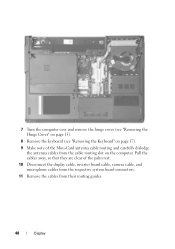
7 Turn the computer over and remove the hinge cover (see "Removing the Hinge Cover" on page 15). 8 Remove the keyboard (see "Removing the Keyboard" on the computer. Pull the cables away, so that they are clear of the palm rest. 10 Disconnect the display cable, inverter board cable, camera cable, and microphone cables from the respective system board connectors. 11 Remove the cables from the cable routing slot on page 17). 9 Make note of the Mini-Card antenna cable routing and carefully dislodge the antenna cables from their routing guides. 48 Display
7 Turn the computer over and remove the hinge cover (see "Removing the Hinge Cover" on page 15). 8 Remove the keyboard (see "Removing the Keyboard" on the computer. Pull the cables away, so that they are clear of the palm rest. 10 Disconnect the display cable, inverter board cable, camera cable, and microphone cables from the respective system board connectors. 11 Remove the cables from the cable routing slot on page 17). 9 Make note of the Mini-Card antenna cable routing and carefully dislodge the antenna cables from their routing guides. 48 Display
Service Manual
Page 51
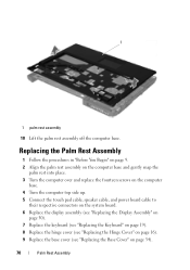
... board. 6 Route the Mini-Card antenna cables, and guide the cables to the bottom of the computer through the cable routing slot. 7 Replace the keyboard (see "Replacing the Keyboard" on page 19). 8 Replace the hinge cover (see "Replacing the Hinge Cover" on page 16). 9 Replace the four screws that secure the display...
... board. 6 Route the Mini-Card antenna cables, and guide the cables to the bottom of the computer through the cable routing slot. 7 Replace the keyboard (see "Replacing the Keyboard" on page 19). 8 Replace the hinge cover (see "Replacing the Hinge Cover" on page 16). 9 Replace the four screws that secure the display...
Service Manual
Page 63
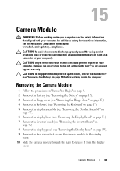
... computer. Camera Module 63 15 Camera Module WARNING: Before working inside your computer, read the safety information that is not authorized by Dell™ is not covered by periodically touching an unpainted metal surface (such as a connector on your warranty. Damage due to servicing that...see "Removing the Battery" on page 13). 3 Remove the hinge cover (see "Removing the Hinge Cover" on page 15). 4 Remove the keyboard (see "Removing the Keyboard" on page 17). 5 Remove the display assembly (see "Removing the Display Assembly" on page 47). 6 Remove the display bezel (see "...
... computer. Camera Module 63 15 Camera Module WARNING: Before working inside your computer, read the safety information that is not authorized by Dell™ is not covered by periodically touching an unpainted metal surface (such as a connector on your warranty. Damage due to servicing that...see "Removing the Battery" on page 13). 3 Remove the hinge cover (see "Removing the Hinge Cover" on page 15). 4 Remove the keyboard (see "Removing the Keyboard" on page 17). 5 Remove the display assembly (see "Removing the Display Assembly" on page 47). 6 Remove the display bezel (see "...
Service Manual
Page 65
Camera Module 65 8 Replace the display assembly (see "Replacing the Display Assembly" on page 50). 9 Replace the keyboard (see "Replacing the Keyboard" on page 19). 10 Replace the hinge cover (see "Replacing the Hinge Cover" on page 16). 11 Replace the battery (see "Replacing the Battery" on page 14).
Camera Module 65 8 Replace the display assembly (see "Replacing the Display Assembly" on page 50). 9 Replace the keyboard (see "Replacing the Keyboard" on page 19). 10 Replace the hinge cover (see "Replacing the Hinge Cover" on page 16). 11 Replace the battery (see "Replacing the Battery" on page 14).
Service Manual
Page 67
... base. Damage due to the system board, remove the main battery (see "Removing the Display Assembly" on page 15). 5 Remove the keyboard (see the Regulatory Compliance Homepage at www.dell.com/regulatory_compliance. 16 Palm Rest Assembly WARNING: Before working inside your computer, read the safety information that shipped with your computer). Palm...
... base. Damage due to the system board, remove the main battery (see "Removing the Display Assembly" on page 15). 5 Remove the keyboard (see the Regulatory Compliance Homepage at www.dell.com/regulatory_compliance. 16 Palm Rest Assembly WARNING: Before working inside your computer, read the safety information that shipped with your computer). Palm...
Service Manual
Page 70
... board cable to their respective connectors on the system board. 6 Replace the display assembly (see "Replacing the Display Assembly" on page 50). 7 Replace the keyboard (see "Replacing the Keyboard" on page 19). 8 Replace the hinge cover (see "Replacing the Hinge Cover" on page 16). 9 Replace the base cover (see "Replacing the Base...
... board cable to their respective connectors on the system board. 6 Replace the display assembly (see "Replacing the Display Assembly" on page 50). 7 Replace the keyboard (see "Replacing the Keyboard" on page 19). 8 Replace the hinge cover (see "Replacing the Hinge Cover" on page 16). 9 Replace the base cover (see "Replacing the Base...
Service Manual
Page 73
CAUTION: Only a certified service technician should perform repairs on your computer, read the safety information that is not authorized by Dell™ is also visible on a barcode label on the bottom of the computer. System Board 73 CAUTION: Handle components and cards by ...(see "Removing the Base Cover" on page 33). 4 Remove the hinge cover (see "Removing the Hinge Cover" on page 15). 5 Remove the keyboard (see "Removing the Keyboard" on page 17). 6 Remove the display assembly (see "Removing the Display Assembly" on page 13) before working inside the computer. CAUTION: To help...
CAUTION: Only a certified service technician should perform repairs on your computer, read the safety information that is not authorized by Dell™ is also visible on a barcode label on the bottom of the computer. System Board 73 CAUTION: Handle components and cards by ...(see "Removing the Base Cover" on page 33). 4 Remove the hinge cover (see "Removing the Hinge Cover" on page 15). 5 Remove the keyboard (see "Removing the Keyboard" on page 17). 6 Remove the display assembly (see "Removing the Display Assembly" on page 13) before working inside the computer. CAUTION: To help...
Service Manual
Page 77
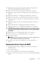
... (see "Replacing the Palm Rest Assembly" on page 70). 15 Replace the display assembly (see "Replacing the Display Assembly" on page 50). 16 Replace the keyboard (see "Replacing the Keyboard" on page 19). 17 Replace the hinge cover (see "Replacing the Hinge Cover" on page 77).
... (see "Replacing the Palm Rest Assembly" on page 70). 15 Replace the display assembly (see "Replacing the Display Assembly" on page 50). 16 Replace the keyboard (see "Replacing the Keyboard" on page 19). 17 Replace the hinge cover (see "Replacing the Hinge Cover" on page 77).


