Owner's Manual
Page 20
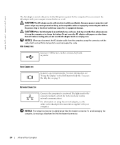
... inside a carrying case. NOTICE: The network connector is slightly larger than the modem connector. CAUTION: Place the AC adapter in the Dell Inspiron Help file. For information on using the network adapter, see the online network-adapter documentation supplied with your computer. However, power connectors...To access the help file, see "Using the Display" in a ventilated area, such as a mouse, keyboard, or printer. Do not cover the AC adapter with electrical outlets worldwide. USB CONNECTORS Connects USB devices, such as a desk top or on or off. NETWORK CONNECTOR Connects ...
... inside a carrying case. NOTICE: The network connector is slightly larger than the modem connector. CAUTION: Place the AC adapter in the Dell Inspiron Help file. For information on using the network adapter, see the online network-adapter documentation supplied with your computer. However, power connectors...To access the help file, see "Using the Display" in a ventilated area, such as a mouse, keyboard, or printer. Do not cover the AC adapter with electrical outlets worldwide. USB CONNECTORS Connects USB devices, such as a desk top or on or off. NETWORK CONNECTOR Connects ...

Owner's Manual
Page 21
... cause a fire. Fan noise is running. Do not store your computer in the air vents. Covers the compartment that contains the modem and Mini PCI card. Bottom View modem/Mini PCI card... cover battery/battery bay hard drive air vent memory module cover battery latch release M O D E M / M I N I P C I V E - A IR VE N T S - B A T T E R Y L A T C H R E L E A S E - H A R D D R I C A R D C O V E R - See page 29. A Tour of Your Computer 21 B A T T E R Y / B A T T E R Y B A Y - See page...
... cause a fire. Fan noise is running. Do not store your computer in the air vents. Covers the compartment that contains the modem and Mini PCI card. Bottom View modem/Mini PCI card... cover battery/battery bay hard drive air vent memory module cover battery latch release M O D E M / M I N I P C I V E - A IR VE N T S - B A T T E R Y L A T C H R E L E A S E - H A R D D R I C A R D C O V E R - See page 29. A Tour of Your Computer 21 B A T T E R Y / B A T T E R Y B A Y - See page...
Owner's Manual
Page 29
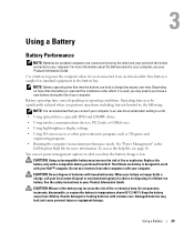
... the safety instructions in maximum performance mode. Keep the battery away from other power-intensive programs such as standard equipment in the Dell Inspiron Help file for advice on disposing of a lithium-ion battery. Replace the battery only with your computer. Do not puncture, ...be significantly reduced when you perform operations including, but not limited to work with your Dell™ computer. Using a Battery Battery Performance NOTE: Batteries for portable computers are covered only during the life of your computer. CAUTION: Using an incompatible battery may need ...
... the safety instructions in maximum performance mode. Keep the battery away from other power-intensive programs such as standard equipment in the Dell Inspiron Help file for advice on disposing of a lithium-ion battery. Replace the battery only with your computer. Do not puncture, ...be significantly reduced when you perform operations including, but not limited to work with your Dell™ computer. Using a Battery Battery Performance NOTE: Batteries for portable computers are covered only during the life of your computer. CAUTION: Using an incompatible battery may need ...
Owner's Manual
Page 58
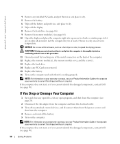
... page 90). 58 Solving Problems If the computer does not start , or if you cannot identify the damaged components, contact Dell (see page 90). www.dell.com | support.dell.com 4 Remove any installed PC Cards, and put them in a safe place to dry. 5 Remove the battery. 6 Wipe off the battery and put ... procedure. 11 Ground yourself by touching one of the metal connectors on the back of the computer. 12 Replace the memory module(s), the memory module cover, and the screw(s). 13 Replace the hard drive. 14 Replace any PC Cards you removed. 15 Replace the battery. 16 Turn on your warranty coverage...
... page 90). 58 Solving Problems If the computer does not start , or if you cannot identify the damaged components, contact Dell (see page 90). www.dell.com | support.dell.com 4 Remove any installed PC Cards, and put them in a safe place to dry. 5 Remove the battery. 6 Wipe off the battery and put ... procedure. 11 Ground yourself by touching one of the metal connectors on the back of the computer. 12 Replace the memory module(s), the memory module cover, and the screw(s). 13 Replace the hard drive. 14 Replace any PC Cards you removed. 15 Replace the battery. 16 Turn on your warranty coverage...

Owner's Manual
Page 65
... You Begin This section provides procedures for removing and installing the components in your warranty. Damage due to servicing that is not authorized by Dell is not covered by its pins. Do not touch the components or contacts on the cable itself. Some cables have read the safety information in your Product...
... You Begin This section provides procedures for removing and installing the components in your warranty. Damage due to servicing that is not authorized by Dell is not covered by its pins. Do not touch the components or contacts on the cable itself. Some cables have read the safety information in your Product...

Owner's Manual
Page 66
...cable, first plug the cable into the computer. 7 Remove any attached devices are extremely fragile; even a slight bump can damage the drive. NOTE: Dell does not guarantee compatibility or provide support for hard drives from the PC Card slot. 8 Close the display and turn off when you service the... latch release on , in standby mode, or in hibernate mode. Do not remove the hard drive while the computer is connected to prevent the computer cover from being scratched. 2 Shut down your docking device for 4 seconds. 4 If the computer is on the bottom of the hard drive. NOTICE: ...
...cable, first plug the cable into the computer. 7 Remove any attached devices are extremely fragile; even a slight bump can damage the drive. NOTE: Dell does not guarantee compatibility or provide support for hard drives from the PC Card slot. 8 Close the display and turn off when you service the... latch release on , in standby mode, or in hibernate mode. Do not remove the hard drive while the computer is connected to prevent the computer cover from being scratched. 2 Shut down your docking device for 4 seconds. 4 If the computer is on the bottom of the hard drive. NOTICE: ...
Owner's Manual
Page 68
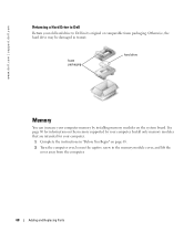
... page 80 for your computer. 1 Complete the instructions in the memory module cover, and lift the cover away from the computer. 68 Adding and Replacing Parts www.dell.com | support.dell.com Returning a Hard Drive to Dell Return your old hard drive to Dell in transit. Otherwise, the hard drive may be damaged in its original...
... page 80 for your computer. 1 Complete the instructions in the memory module cover, and lift the cover away from the computer. 68 Adding and Replacing Parts www.dell.com | support.dell.com Returning a Hard Drive to Dell Return your old hard drive to Dell in transit. Otherwise, the hard drive may be damaged in its original...

Owner's Manual
Page 69
memory module securing clips Adding and Replacing Parts 69 captive screw memory module cover NOTE: Memory modules purchased from the connector. b Remove the module from Dell are covered under your computer warranty. 3 If you are replacing a memory module, remove the existing module: a Use your fingertips to carefully spread apart the securing clips on each end of the memory module connector until the module pops up.
memory module securing clips Adding and Replacing Parts 69 captive screw memory module cover NOTE: Memory modules purchased from the connector. b Remove the module from Dell are covered under your computer warranty. 3 If you are replacing a memory module, remove the existing module: a Use your fingertips to carefully spread apart the securing clips on each end of the memory module connector until the module pops up.

Owner's Manual
Page 70
...dell.com | support.dell.com 4 Ground yourself and install the new memory module: NOTE: If the memory module is difficult to close may not boot properly. To confirm the amount of memory installed in the connector slot. No error message indicates this failure. b Slide the module firmly into place. Forcing the cover...Start button, click Help and Support, and then click Computer Information. 70 Adding and Replacing Parts NOTICE: If the memory module cover is not installed properly, the computer may damage your computer. 6 Insert the battery into the battery bay, or connect the AC...
...dell.com | support.dell.com 4 Ground yourself and install the new memory module: NOTE: If the memory module is difficult to close may not boot properly. To confirm the amount of memory installed in the connector slot. No error message indicates this failure. b Slide the module firmly into place. Forcing the cover...Start button, click Help and Support, and then click Computer Information. 70 Adding and Replacing Parts NOTICE: If the memory module cover is not installed properly, the computer may damage your computer. 6 Insert the battery into the battery bay, or connect the AC...

Owner's Manual
Page 71
captive screw modem/Mini PCI card cover 3 Continue to the appropriate section: • To add a modem, see the following section, "Adding a Modem." • To add a Mini PCI card, see page 72. Adding and Replacing Parts 71 Modem and Mini PCI Card 1 Complete the instructions in "Before You Begin" on page 65. 2 Turn the computer over, loosen the captive screw on the modem/Mini PCI card cover, and lift the cover away from the computer.
captive screw modem/Mini PCI card cover 3 Continue to the appropriate section: • To add a modem, see the following section, "Adding a Modem." • To add a Mini PCI card, see page 72. Adding and Replacing Parts 71 Modem and Mini PCI Card 1 Complete the instructions in "Before You Begin" on page 65. 2 Turn the computer over, loosen the captive screw on the modem/Mini PCI card cover, and lift the cover away from the computer.

Owner's Manual
Page 72
... Mini PCI Cards may be purchased only from installing 5 GHz (802.11a, 802.11a/b, 802.11a/b/g) Wireless LAN Mini PCI cards. Only trained Dell service personnel are removing and/or installing a 2.4 GHz (802.11b, 802.11b/g) Mini PCI Card, please follow the instructions noted below. screws ...modem cable. Under no circumstances should the user install such a device. If you are authorized to the system board. 5 Replace the cover. www.dell.com | support.dell.com Replacing the Modem 1 Remove the existing modem: a Remove the screws securing the modem to the modem. b Pull straight up on...
... Mini PCI Cards may be purchased only from installing 5 GHz (802.11a, 802.11a/b, 802.11a/b/g) Wireless LAN Mini PCI cards. Only trained Dell service personnel are removing and/or installing a 2.4 GHz (802.11b, 802.11b/g) Mini PCI Card, please follow the instructions noted below. screws ...modem cable. Under no circumstances should the user install such a device. If you are authorized to the system board. 5 Replace the cover. www.dell.com | support.dell.com Replacing the Modem 1 Remove the existing modem: a Remove the screws securing the modem to the modem. b Pull straight up on...

Owner's Manual
Page 74
Mini PCI card antenna cables (2) Mini PCI card connector 3 Connect the antenna cables to the Mini PCI card. 4 Replace the cover. 74 Adding and Replacing Parts www.dell.com | support.dell.com 2 Align the Mini PCI card with the connector at a 45-degree angle, and press the Mini PCI card into the connector until it clicks.
Mini PCI card antenna cables (2) Mini PCI card connector 3 Connect the antenna cables to the Mini PCI card. 4 Replace the cover. 74 Adding and Replacing Parts www.dell.com | support.dell.com 2 Align the Mini PCI card with the connector at a 45-degree angle, and press the Mini PCI card into the connector until it clicks.

Owner's Manual
Page 75
CD or DVD Drive 1 Complete the instructions in "Before You Begin" on page 65. 2 Turn the computer over, loosen the captive screw in the memory module cover, and lift the cover away from the computer. CD or DVD drive screw lever Adding and Replacing Parts 75 captive screw memory module cover 3 Remove the screw labeled "O" next to the memory module cover.
CD or DVD Drive 1 Complete the instructions in "Before You Begin" on page 65. 2 Turn the computer over, loosen the captive screw in the memory module cover, and lift the cover away from the computer. CD or DVD drive screw lever Adding and Replacing Parts 75 captive screw memory module cover 3 Remove the screw labeled "O" next to the memory module cover.
Owner's Manual
Page 76
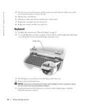
...hinges so that the keyboard connector is fully seated. 7 Replace the screw that you removed in step 3. 8 Replace the memory module cover and screw. hinge cover 3 Lift the hinge cover up and away from the hinges and bottom case. Keyboard 1 Complete the instructions in "Before You Begin" on page 65. 2..., easily dislodged, and time-consuming to lift the notched right edge of the hinge cover, and pry the cover loose from the hinges and bottom case. 4 Remove the four keyboard screws. www.dell.com | support.dell.com 4 Press the lever next to the memory module connectors in the direction of...
...hinges so that the keyboard connector is fully seated. 7 Replace the screw that you removed in step 3. 8 Replace the memory module cover and screw. hinge cover 3 Lift the hinge cover up and away from the hinges and bottom case. Keyboard 1 Complete the instructions in "Before You Begin" on page 65. 2..., easily dislodged, and time-consuming to lift the notched right edge of the hinge cover, and pry the cover loose from the hinges and bottom case. 4 Remove the four keyboard screws. www.dell.com | support.dell.com 4 Press the lever next to the memory module connectors in the direction of...

Owner's Manual
Page 78
keyboard screws (4) keyboard keyboard connector interface connector securing tabs (4) 9 Insert the four securing tabs on the system board. www.dell.com | support.dell.com 8 Connect the keyboard connector of the replacement keyboard to completely seat the keyboard. 10 Replace the four keyboard screws. 11 Replace the hinge cover. 78 Adding and Replacing Parts Ensure that all four securing tabs are engaged before trying to the interface connector on the keyboard into their respective slots in the palm rest, and lower the keyboard into the bottom case.
keyboard screws (4) keyboard keyboard connector interface connector securing tabs (4) 9 Insert the four securing tabs on the system board. www.dell.com | support.dell.com 8 Connect the keyboard connector of the replacement keyboard to completely seat the keyboard. 10 Replace the four keyboard screws. 11 Replace the hinge cover. 78 Adding and Replacing Parts Ensure that all four securing tabs are engaged before trying to the interface connector on the keyboard into their respective slots in the palm rest, and lower the keyboard into the bottom case.
Owner's Manual
Page 89
...meter icon on usage. For more information on power management, see page 9. To access the help file, see the Dell Inspiron Help file. Dell provides limited technical support for restoration of the operating system, software programs, and hardware drivers to this technician-assisted technical ...run your computer at high system activity levels for purchase. Variable Speed Fan The computer uses a variable speed fan to cover all Dell-installed hardware. Support for third-party software and peripherals is provided by the original manufacturer, including those purchased and/or ...
...meter icon on usage. For more information on power management, see page 9. To access the help file, see the Dell Inspiron Help file. Dell provides limited technical support for restoration of the operating system, software programs, and hardware drivers to this technician-assisted technical ...run your computer at high system activity levels for purchase. Variable Speed Fan The computer uses a variable speed fan to cover all Dell-installed hardware. Support for third-party software and peripherals is provided by the original manufacturer, including those purchased and/or ...

Owner's Manual
Page 91
...; Increase the separation between the equipment and the receiver. • Connect the equipment into an outlet on the device or devices covered in this document in a particular installation. Country (City) International Access Code Country Code City Code Anguilla Antigua and Barbuda Department Name...8226; Consult the dealer or an experienced radio/television technician for help. One Dell Way Round Rock, Texas 78682 USA 512-338-4400 Contacting Dell To contact Dell electronically, you need to contact Dell, use the electronic addresses, telephone numbers, and codes provided in the table ...
...; Increase the separation between the equipment and the receiver. • Connect the equipment into an outlet on the device or devices covered in this document in a particular installation. Country (City) International Access Code Country Code City Code Anguilla Antigua and Barbuda Department Name...8226; Consult the dealer or an experienced radio/television technician for help. One Dell Way Round Rock, Texas 78682 USA 512-338-4400 Contacting Dell To contact Dell electronically, you need to contact Dell, use the electronic addresses, telephone numbers, and codes provided in the table ...
Owner's Manual
Page 110
...copying, 41 E e-mail fixing problems, 25 F floppy drive fixing problems, 55 H hard drive description, 21 replacing, 66 returning to Dell, 68 system view, 21 hardware Dell Diagnostics, 49 Hardware Troubleshooter, 60 Help and Support Center, 11 help file, 10 I installing parts before you begin, 65 recommended tools,...view, 14 keypad numeric, 33 L labels Microsoft Windows, 10 Service Tag, 10 line conditioners, 28 M memory removing, 69 memory module cover description, 21 system view, 21 Microsoft Windows label, 10 modem adding, 72 modem connector description, 18 system view, 18 modem/Mini PCI card...
...copying, 41 E e-mail fixing problems, 25 F floppy drive fixing problems, 55 H hard drive description, 21 replacing, 66 returning to Dell, 68 system view, 21 hardware Dell Diagnostics, 49 Hardware Troubleshooter, 60 Help and Support Center, 11 help file, 10 I installing parts before you begin, 65 recommended tools,...view, 14 keypad numeric, 33 L labels Microsoft Windows, 10 Service Tag, 10 line conditioners, 28 M memory removing, 69 memory module cover description, 21 system view, 21 Microsoft Windows label, 10 modem adding, 72 modem connector description, 18 system view, 18 modem/Mini PCI card...


