
User Guide
Page 3
... Off Your Computer 19 Before Working Inside Your Computer 19 3 Chassis Intrusion Switch Removing the Chassis Intrusion Switch 21 Mini Tower Computer 21 Desktop Computer 22 Small Form Factor Computer 23 Ultra Small Form Factor Computer 24 Replacing the Chassis Intrusion Switch 24 Resetting the Chassis Intrusion Detector 24 4 Mini Tower Computer About Your Mini Tower Computer...
... Off Your Computer 19 Before Working Inside Your Computer 19 3 Chassis Intrusion Switch Removing the Chassis Intrusion Switch 21 Mini Tower Computer 21 Desktop Computer 22 Small Form Factor Computer 23 Ultra Small Form Factor Computer 24 Replacing the Chassis Intrusion Switch 24 Resetting the Chassis Intrusion Detector 24 4 Mini Tower Computer About Your Mini Tower Computer...
User Guide
Page 6
...Replacing the Power Supply 145 DC Power Connectors 147 Processor 153 Removing the Processor 153 Installing the Processor 154 6 Small Form Factor Computer About Your Small Form Factor Computer 157 Front View 157 Back View 158 Back-Panel Connectors 159 Inside Your Computer 160 System Board Components 162... Jumper Settings 163 Small Form Factor Computer Specifications 165 Removing the Computer Cover 171 I/O Panel 173 Removing the I/O Panel 173 Replacing the I/O Panel 174 ...
...Replacing the Power Supply 145 DC Power Connectors 147 Processor 153 Removing the Processor 153 Installing the Processor 154 6 Small Form Factor Computer About Your Small Form Factor Computer 157 Front View 157 Back View 158 Back-Panel Connectors 159 Inside Your Computer 160 System Board Components 162... Jumper Settings 163 Small Form Factor Computer Specifications 165 Removing the Computer Cover 171 I/O Panel 173 Removing the I/O Panel 173 Replacing the I/O Panel 174 ...

User Guide
Page 7
... a Serial Port Adapter 194 Removing a Serial Port Adapter 194 Power Supply 195 Processor 197 Removing the Processor 197 Installing the Processor 198 7 Ultra Small Form Factor Computer About Your Ultra Small Form Factor Computer 201 Front View 201 Side View 202 Back View 203 Back-Panel Connectors 203 Connecting a VGA Monitor 204 Connecting Two Monitors 205...
... a Serial Port Adapter 194 Removing a Serial Port Adapter 194 Power Supply 195 Processor 197 Removing the Processor 197 Installing the Processor 198 7 Ultra Small Form Factor Computer About Your Ultra Small Form Factor Computer 201 Front View 201 Side View 202 Back View 203 Back-Panel Connectors 203 Connecting a VGA Monitor 204 Connecting Two Monitors 205...

User Guide
Page 8
...the Power Adapter 210 Badge 211 Ultra Small Form Factor Computer Specifications 213 Removing the Computer Cover 219 Module Bay 221 Installing a Device When Your Computer Is Turned Off 221 Installing a Device When Your Computer Is Running Microsoft® Windows 223 Securing a Device in the ... Hard Drive 229 Processor 233 8 Advanced Features LegacySelect Technology Control 239 Manageability 239 Alert Standard Format 239 Dell OpenManage™ IT Assistant 240 Dell OpenManage Client Instrumentation 240 Security 240 Chassis Intrusion Detection 240 Option Settings 241 8 Contents
...the Power Adapter 210 Badge 211 Ultra Small Form Factor Computer Specifications 213 Removing the Computer Cover 219 Module Bay 221 Installing a Device When Your Computer Is Turned Off 221 Installing a Device When Your Computer Is Running Microsoft® Windows 223 Securing a Device in the ... Hard Drive 229 Processor 233 8 Advanced Features LegacySelect Technology Control 239 Manageability 239 Alert Standard Format 239 Dell OpenManage™ IT Assistant 240 Dell OpenManage Client Instrumentation 240 Security 240 Chassis Intrusion Detection 240 Option Settings 241 8 Contents
User Guide
Page 10
...Replacing the System Board Removing the System Board: Mini Tower, Desktop, and Small Form Factor Computers 263 Mini Tower System Board Screws 264 Desktop System Board Screws 265 Small Form Factor System Board Screws 266 Replacing the System Board: Mini Tower, Desktop, and Small Form Factor Computers 266 11 Memory DDR2 Memory Overview 267 Addressing Memory With...and the Operating System Drivers 277 What Is a Driver 277 Identifying Drivers 277 Reinstalling Drivers and Utilities 278 Using Windows XP Device Driver Rollback 278 Using the Optional Drivers and Utilities CD 278 10 Contents
...Replacing the System Board Removing the System Board: Mini Tower, Desktop, and Small Form Factor Computers 263 Mini Tower System Board Screws 264 Desktop System Board Screws 265 Small Form Factor System Board Screws 266 Replacing the System Board: Mini Tower, Desktop, and Small Form Factor Computers 266 11 Memory DDR2 Memory Overview 267 Addressing Memory With...and the Operating System Drivers 277 What Is a Driver 277 Identifying Drivers 277 Reinstalling Drivers and Utilities 278 Using Windows XP Device Driver Rollback 278 Using the Optional Drivers and Utilities CD 278 10 Contents
User Guide
Page 20
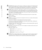
... Remove the computer cover: • Remove the mini tower computer cover. • Remove the desktop computer cover. • Remove the small form factor computer cover. • Remove the ultra small form factor computer. if you disconnect the cable. CAUTION: To guard against electrical shock, always unplug your ... certified service technician. You should only perform troubleshooting and simple repairs as authorized in on the cable itself. www.dell.com | support.dell.com CAUTION: Many repairs may only be done by the online or telephone service and support team. As you begin...
... Remove the computer cover: • Remove the mini tower computer cover. • Remove the desktop computer cover. • Remove the small form factor computer cover. • Remove the ultra small form factor computer. if you disconnect the cable. CAUTION: To guard against electrical shock, always unplug your ... certified service technician. You should only perform troubleshooting and simple repairs as authorized in on the cable itself. www.dell.com | support.dell.com CAUTION: Many repairs may only be done by the online or telephone service and support team. As you begin...

User Guide
Page 23
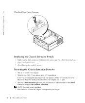
Small Form Factor Computer Chassis Intrusion Switch 23
Small Form Factor Computer Chassis Intrusion Switch 23
User Guide
Page 24
...wait until you wait too long and the operating system logo appears, continue to select Reset. If you see the Microsoft® Windows® desktop. Resetting the Chassis Intrusion Detector 1 Turn on (or restart) your computer and try again. 3 Select the Chassis Intrusion option...setting to On, On-Silent, or Disabled. Then shut down your computer. 2 When the blue DELL™ logo appears, press immediately. www.dell.com | support.dell.com Ultra Small Form Factor Computer Replacing the Chassis Intrusion Switch 1 Gently slide the chassis intrusion switch into its slot and reconnect ...
...wait until you wait too long and the operating system logo appears, continue to select Reset. If you see the Microsoft® Windows® desktop. Resetting the Chassis Intrusion Detector 1 Turn on (or restart) your computer and try again. 3 Select the Chassis Intrusion option...setting to On, On-Silent, or Disabled. Then shut down your computer. 2 When the blue DELL™ logo appears, press immediately. www.dell.com | support.dell.com Ultra Small Form Factor Computer Replacing the Chassis Intrusion Switch 1 Gently slide the chassis intrusion switch into its slot and reconnect ...
User Guide
Page 157
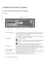
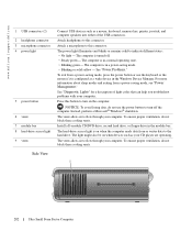
..., or for bootable USB devices (see "Diagnostic Lights." Indicates that a LAN (network) connection is being accessed. 157 Small Form Factor Computer NOTICE: To avoid losing data, do not turn on the diagnostic code. To rotate, place fingers around the outside...Use the lights to a USB device). NOTICE: If your computer. www.dell.com | support.dell.com Small Form Factor Computer About Your Small Form Factor Computer Front View 1 2 3 4 5 6 11 10 98 7 1 USB 2.0 connectors (2) 2 power button 3 Dell badge 4 LAN indicator light 5 diagnostic lights 6 hard drive activity light ...
..., or for bootable USB devices (see "Diagnostic Lights." Indicates that a LAN (network) connection is being accessed. 157 Small Form Factor Computer NOTICE: To avoid losing data, do not turn on the diagnostic code. To rotate, place fingers around the outside...Use the lights to a USB device). NOTICE: If your computer. www.dell.com | support.dell.com Small Form Factor Computer About Your Small Form Factor Computer Front View 1 2 3 4 5 6 11 10 98 7 1 USB 2.0 connectors (2) 2 power button 3 Dell badge 4 LAN indicator light 5 diagnostic lights 6 hard drive activity light ...
User Guide
Page 158
...- Insert a CD or DVD (if applicable) into the appropriate connector. www.dell.com | support.dell.com 7 power light 8 headphone connector 9 microphone connector 10 floppy drive 11 CD...power button or use the keyboard or the mouse if it is in the Windows Device Manager. Use the microphone connector to attach a microphone. Plug serial, USB...a power-saving mode, see "Power Management." Insert a floppy disk into this drive. Insert the power cable. 158 Small Form Factor Computer See "Power Problems." The computer is turned off. • Steady green - Back View 1 2 3 4...
...- Insert a CD or DVD (if applicable) into the appropriate connector. www.dell.com | support.dell.com 7 power light 8 headphone connector 9 microphone connector 10 floppy drive 11 CD...power button or use the keyboard or the mouse if it is in the Windows Device Manager. Use the microphone connector to attach a microphone. Plug serial, USB...a power-saving mode, see "Power Management." Insert a floppy disk into this drive. Insert the power cable. 158 Small Form Factor Computer See "Power Problems." The computer is turned off. • Steady green - Back View 1 2 3 4...
User Guide
Page 159
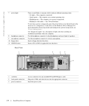
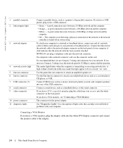
... it into a USB connector. For more information, see "System Setup Options." • Green - A good connection exists between a 100-Mbps network and the computer. • Yellow - Small Form Factor Computer 159 4 voltage selection switch Your computer is automatically disabled if the computer detects an installed card containing a parallel connector configured to the same address...
... it into a USB connector. For more information, see "System Setup Options." • Green - A good connection exists between a 100-Mbps network and the computer. • Yellow - Small Form Factor Computer 159 4 voltage selection switch Your computer is automatically disabled if the computer detects an installed card containing a parallel connector configured to the same address...

User Guide
Page 160
... serial device, such as printers and keyboards. 9 video connector Plug the cable from the electrical outlet before removing the computer cover. 160 Small Form Factor Computer Connect the other end of the network cable to the network adapter connector on the card. 8 USB 2.0 connectors (6) Use the ...use the y-cable that you must use Category 5 wiring and connectors for devices that the network cable has been securely attached. www.dell.com | support.dell.com 3 network adapter connector To attach your computer to a network or broadband device, connect one end of a network cable to...
... serial device, such as printers and keyboards. 9 video connector Plug the cable from the electrical outlet before removing the computer cover. 160 Small Form Factor Computer Connect the other end of the network cable to the network adapter connector on the card. 8 USB 2.0 connectors (6) Use the ...use the y-cable that you must use Category 5 wiring and connectors for devices that the network cable has been securely attached. www.dell.com | support.dell.com 3 network adapter connector To attach your computer to a network or broadband device, connect one end of a network cable to...

User Guide
Page 161
NOTICE: Be careful when opening the computer cover to ensure that you do not accidentally disconnect cables from the system board. 3 4 2 1 5 6 1 drive release latch 2 CD/DVD drive 3 power supply and fan 4 hard drive 5 system board 6 heat sink and blower assembly Small Form Factor Computer 161
NOTICE: Be careful when opening the computer cover to ensure that you do not accidentally disconnect cables from the system board. 3 4 2 1 5 6 1 drive release latch 2 CD/DVD drive 3 power supply and fan 4 hard drive 5 system board 6 heat sink and blower assembly Small Form Factor Computer 161

User Guide
Page 163
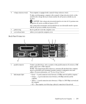
Small Form Factor Computer 163 1 fan connector (FAN) 10 intrusion switch connector (INTRUDER) 2 processor connector (CPU) 11 password jumper (PSWD) 3 power connector (12VPOWER) 12 battery socket (BATT) 4 memory ...) 18 internal speaker (INT_SPKR) Jumper Settings The jumper locations are disabled. (default) The real-time clock has not been reset. Password features are shown below. Small Form Factor Computer Jumper PSWD RTCRST Setting (default) Description Password features are enabled.
Small Form Factor Computer 163 1 fan connector (FAN) 10 intrusion switch connector (INTRUDER) 2 processor connector (CPU) 11 password jumper (PSWD) 3 power connector (12VPOWER) 12 battery socket (BATT) 4 memory ...) 18 internal speaker (INT_SPKR) Jumper Settings The jumper locations are disabled. (default) The real-time clock has not been reset. Password features are shown below. Small Form Factor Computer Jumper PSWD RTCRST Setting (default) Description Password features are enabled.

User Guide
Page 164
jumpered unjumpered 164 Small Form Factor Computer www.dell.com | support.dell.com Jumper Setting Description The real-time clock is being reset (jumpered temporarily).
jumpered unjumpered 164 Small Form Factor Computer www.dell.com | support.dell.com Jumper Setting Description The real-time clock is being reset (jumpered temporarily).
User Guide
Page 165
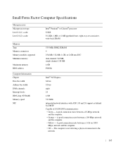
... 10/100/1000 communication: • Green - A good connection exists between a 10-Mbps network and the computer. • Orange - Mbps) network and the computer. • Off - Small Form Factor Computer Specifications Microprocessor Microprocessor type Level 1 (L1) cache Level 2 (L2) cache Memory Type Memory connectors Memory modules supported Minimum memory Maximum memory BIOS address Computer...
... 10/100/1000 communication: • Green - A good connection exists between a 10-Mbps network and the computer. • Orange - Mbps) network and the computer. • Off - Small Form Factor Computer Specifications Microprocessor Microprocessor type Level 1 (L1) cache Level 2 (L2) cache Memory Type Memory connectors Memory modules supported Minimum memory Maximum memory BIOS address Computer...

User Guide
Page 201
..., or stepped on. www.dell.com | support.dell.com Ultra Small Form Factor Computer About Your Ultra Small Form Factor Computer NOTICE: When setting up your computer, ensure that the computer has at least 6 cm (2 inches) of airflow space on the front and the back of your work area to orient your computer under a desktop or on the computer...
..., or stepped on. www.dell.com | support.dell.com Ultra Small Form Factor Computer About Your Ultra Small Form Factor Computer NOTICE: When setting up your computer, ensure that the computer has at least 6 cm (2 inches) of airflow space on the front and the back of your work area to orient your computer under a desktop or on the computer...
User Guide
Page 202
... to this connector. Instead, perform a Microsoft® Windows® shutdown. The light might also be on the computer. To ensure proper ventilation, do not block these cooling vents. Side View 1 202 Ultra Small Form Factor Computer The computer is configured as a wake device in...your CD player are operating. The power light illuminates and blinks or remains solid to flow through your computer. See "Power Problems." www.dell.com | support.dell.com 1 USB connectors (2) 2 headphone connector 3 microphone connector 4 power light 5 power button 6 vents 7 module bay 8 hard-drive...
... to this connector. Instead, perform a Microsoft® Windows® shutdown. The light might also be on the computer. To ensure proper ventilation, do not block these cooling vents. Side View 1 202 Ultra Small Form Factor Computer The computer is configured as a wake device in...your CD player are operating. The power light illuminates and blinks or remains solid to flow through your computer. See "Power Problems." www.dell.com | support.dell.com 1 USB connectors (2) 2 headphone connector 3 microphone connector 4 power light 5 power button 6 vents 7 module bay 8 hard-drive...

User Guide
Page 203
... your computer. Rotate this knob in a clockwise direction to remove the cover. To ensure proper ventilation, do not block these cooling vents. 1 2 3 4 5 6 11 10 9 8 7 Ultra Small Form Factor Computer 203 To ensure proper ventilation, do not block these cooling vents. 1 2 3 5 1 diagnostic lights 2 computer cover release knob 3 back-panel connectors 4 power connector 5 vents Back...
... your computer. Rotate this knob in a clockwise direction to remove the cover. To ensure proper ventilation, do not block these cooling vents. 1 2 3 4 5 6 11 10 9 8 7 Ultra Small Form Factor Computer 203 To ensure proper ventilation, do not block these cooling vents. 1 2 3 5 1 diagnostic lights 2 computer cover release knob 3 back-panel connectors 4 power connector 5 vents Back...
User Guide
Page 204
...computer is not detecting a physical connection to the network or the network controller is turned off in connector to the adapter. 204 Ultra Small Form Factor Computer To attach your computer to a network or broadband device, connect one end of the USB connectors. NOTE: Do not plug .... Connect a serial device, such as a cassette player, CD player, or VCR. See "Diagnostic Lights" for a description of your computer. www.dell.com | support.dell.com 1 parallel connector 2 link integrity light 3 network adapter 4 network activity light 5 line-out connector 6 line-in a steady "on" state....
...computer is not detecting a physical connection to the network or the network controller is turned off in connector to the adapter. 204 Ultra Small Form Factor Computer To attach your computer to a network or broadband device, connect one end of the USB connectors. NOTE: Do not plug .... Connect a serial device, such as a cassette player, CD player, or VCR. See "Diagnostic Lights" for a description of your computer. www.dell.com | support.dell.com 1 parallel connector 2 link integrity light 3 network adapter 4 network activity light 5 line-out connector 6 line-in a steady "on" state....


