
Dell OptiPlex 755 Support Question
Dell OptiPlex 755 Support Question
Find answers below for this question about Dell OptiPlex 755.Need a Dell OptiPlex 755 manual? We have 3 online manuals for this item!
Question posted by ladybqatmus on September 17th, 2013
How To Remove Hard Drive From Optiplex 755 Small Form Factor
The person who posted this question about this Dell product did not include a detailed explanation. Please use the "Request More Information" button to the right if more details would help you to answer this question.
Current Answers
Related Dell OptiPlex 755 Manual Pages
Quick Reference
Guide - Page 3
... Computer 16 System Views 16 Removing the Computer Cover 22 Inside Your Computer 24 System Board Components 25 Jumper Settings 26
Desktop Computer 27 System Views 27 Removing the Computer Cover 32 Inside Your Computer 33 System Board Components 35 Jumper Settings 36
Small Form Factor Computer 37 System Views 37 Removing the Computer Cover 43
Contents...
Quick Reference
Guide - Page 4
Inside Your Computer 44 System Board Components 46 Jumper Settings 47
Ultra Small Form Factor Computer 48 System Views 48 Removing the Computer Cover 55 Inside Your Computer 56 Cable Cover (Optional 57
System Board Components 59 Jumper Settings 60
Solving Problems 61 Dell Diagnostics 61 ...
User's Guide - Page 7
... Chassis Intrusion Switch 170 Replacing the Chassis Intrusion Switch 171 Resetting the Chassis Intrusion Detector 171
System Board Components 172
Small Form Factor Computer Specifications 175
Cards 181 PCI Cards 181 Installing a PCI Card 181 Removing a PCI Card 184 PCI Express and DVI Cards 185 Installing a PCI Express x16 Card or DVI Card 186...
User's Guide - Page 9
...Ultra Small Form Factor Computer Specifications 241
Drives 247 General Installation Guidelines 247 Connecting Drive Cables 247 Data Interface Connectors 247 Power Cable Connectors 248 Connecting and Disconnecting Drive Cables 248 Hard Drive 248 Installing a Hard Drive 249 Replacing a Hard Drive Fan 252
Module Bay 255 Installing a Device When Your Computer Is Turned Off 255 Removing and...
User's Guide - Page 12
... Manager 299 Recovering From a Single Hard Drive Failure (RAID 1) Using the Intel Matrix Storage Manager 300 Migrating to a RAID Level 0 Configuration 301 Migrating to a RAID Level 1 Configuration 301
10 Battery
Replacing the Battery 303
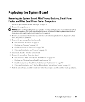
11 Replacing the System Board
Removing the System Board: Mini Tower, Desktop, Small Form Factor, and Ultra Small Form Factor Computers 307
Mini Tower System...
User's Guide - Page 29
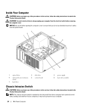
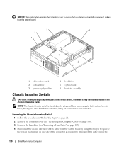
... do not accidentally disconnect cables from the electrical outlet before removing the computer cover. NOTE: The chassis intrusion switch is standard on the ultra small form factor computer but is optional on your computer from the system board.
3
2
1
4
5
6 7
1 optical drive
4 optional chassis-intrusion switch
7 hard drive
2 disk drive 5 system board
3 power supply 6 heat sink assembly...
User's Guide - Page 92
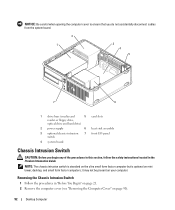
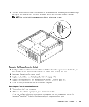
.... 2 Remove the computer cover (see "Removing the Computer Cover" on your computer.
Removing the Chassis Intrusion Switch
1 Follow the procedures in the Product Information Guide. it may not be present on page 90).
92
Desktop Computer
NOTE: The chassis intrusion switch is standard on the ultra small form factor computer but is optional on mini tower, desktop, and small form factor...
User's Guide - Page 165
...local area network) connection is being accessed.
165
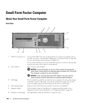
Small Form Factor Computer NOTICE: To avoid losing data, do not turn the badge. Small Form Factor Computer
About Your Small Form Factor Computer
Front View
1
2
3
4
5
6..., see "System Setup" on page 347.
6 hard drive activity light This light flickers when the hard drive is established.
5 diagnostic lights
Use the lights to...
User's Guide - Page 170
...in "Before You Begin" on page 21. 2 Remove the computer cover (see "Removing the Computer Cover" on page 168). 3 Remove the hard drive (see "Removing a Hard Drive" on page 197). 4 Disconnect the chassis intrusion switch cable from the system board by using two fingers to disconnect the cable connector.
170
Small Form Factor Computer Removing the Chassis Intrusion Switch
1 Follow the procedures...
User's Guide - Page 171
... 199). 4 Replace the computer cover (see the Microsoft® Windows® desktop.
If you wait too long and the operating system logo appears, continue to the computer.
Replacing the Chassis Intrusion Switch
1 Gently insert the switch from the computer. Small Form Factor Computer
171 5 Slide the chassis intrusion switch out of the slot. NOTE...
User's Guide - Page 177
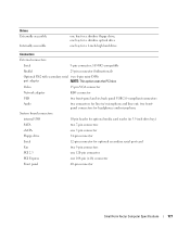
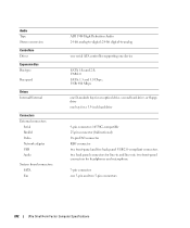
...for a 1-inch-high hard drive
Connectors
External connectors:
Serial
9-pin connector; 16550C-compatible
Parallel
25-pin connector (bidirectional)
Optional PS/2 with secondary serial two 6-pin mini-DINs
port adapter
NOTE: This option uses the PCI slot. Drives Externally accessible
Internally accessible
one 164-pin (x16) connector
Front panel
40-pin connector
Small Form Factor Computer...
User's Guide - Page 178
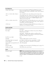
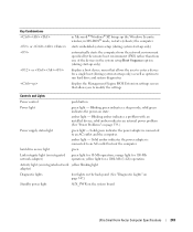
...an installed device; Key Combinations
or
or
If you to run hard drive and system diagnostics
displays the Management Engine BIOS Extension settings screen...
Small Form Factor Computer Specifications blinking green indicates sleep mode; amber light - yellow light for 100-Mb operation; solid amber indicates an internal power problem (See "Power Problems" on page 339.)
hard drive access...
User's Guide - Page 217
... located in "Before You Begin" on page 21. 2 Remove the computer cover (see "Removing the Computer Cover" on page 168). 3 Remove the optical drive and floppy drive from the drive bays, if installed (see "Drives" on page 195). 4 Remove the hard drive (see "Removing a Hard Drive" on page 197). 5 Remove the processor heat sink (see "Small Form Factor System Board Screws" on page 213).
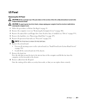
I/O Panel...
User's Guide - Page 228
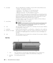
...The light might also be on page 292. For mounting optional stand.
228
Ultra Small Form Factor Computer See "Power Problems" on the computer.
See "Turning Off Your Computer" on...cooling vents. To exit from overheating. Install a D-module optical drive, second hard drive, or floppy drive in the Windows Device Manager. The hard drive access light is in a power-saving mode. • Blinking...
User's Guide - Page 233
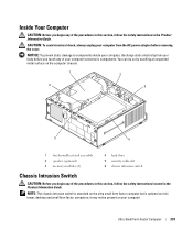
... your body before removing the cover. NOTE: The chassis intrusion switch is standard on the ultra small form factor computer but is optional on your computer's electronic components.
You can do so by touching an unpainted metal surface on the computer chassis.
1
2
6
3
5
4
1 fan shroud/heat sink assembly 2 speaker (optional) 3 memory modules (2)
4 hard drive 5 security cable slot...
User's Guide - Page 242
... back panel USB 2.0-compliant connectors two back panel connectors for an optical drive, second hard drive, or floppy drive one 3-pin and two 5-pin connectors
242
Ultra Small Form Factor Computer Specifications Audio Type Stereo conversion
Controllers Drives
Expansion Bus Bus type
Bus speed
Drives Internal/External
Connectors External connectors:
Serial Parallel Video Network adapter USB Audio...
User's Guide - Page 243
...; Windows® XP, brings up only) as well as options to run hard drive and system diagnostics
displays the Management Engine BIOS Extension settings screen that allows you ... light -
Blinking green indicates a sleep mode; hard drive access light
green
Link integrity light (on the system board
Ultra Small Form Factor Computer Specifications
243 Solid green indicates the power adapter...
User's Guide - Page 282
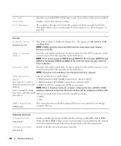
... a boot routine is set to the eSATA connector on the ultra small form factor computer. SATA 0 through SATA 2 for the desktop, SATA 0 and SATA1 for the hard drives.
Drives
Diskette Drive (Internal default)
This option enables or disables the floppy drive.
External SATA
Identifies and enables and disables the drives attached to On. NOTE: This option is configured for RAID...
User's Guide - Page 307
... page 310 • Ultra small form factor: see "Ultra Small Form Factor System Board Screws" on page 21. 2 Remove the computer cover. While you work, periodically touch an unpainted metal surface to dissipate any static electricity that could harm internal components. 3 Remove any components that restrict access to the system board (optical drive[s], floppy drive, hard drive, I/O panel (as the...
User's Guide - Page 317
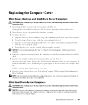
...remove and replace the cover, the chassis intrusion detector (optional on some computers), if installed and enabled, causes the following message to components inside your computer, discharge static electricity from your computer's electronic components.
Replacing the Computer Cover
Mini-Tower, Desktop, and Small Form Factor...do not get caught underneath the drives.
2 Ensure that the cover...
Similar Questions


How To Reset Power On Optiplex 755 Small Form Factor
(Posted by akin1Un 10 years ago)

How To Remove Back Slot On Optiplex 990 Small Form Factor
(Posted by dmassSSA 10 years ago)

How To Remove Hard Drive Desktop Computer Optiplex 755
(Posted by anlo 10 years ago)

Dell Optiplexx 755 Small Form Factor Wont Recognize Keyboarrd
(Posted by starBagg98 10 years ago)