
User Guide
Page 3
...Turning Off Your Computer 19 Before Working Inside Your Computer 19 3 Chassis Intrusion Switch Removing the Chassis Intrusion Switch 21 Mini Tower Computer 21 Desktop Computer 22 Small Form Factor Computer 23 Ultra Small Form Factor Computer 24 Replacing the Chassis Intrusion Switch 24 Resetting ...the Chassis Intrusion Detector 24 4 Mini Tower Computer About Your Mini Tower Computer 25 Front View 25 Back View 27 Back-Panel Connectors 28 ...
...Turning Off Your Computer 19 Before Working Inside Your Computer 19 3 Chassis Intrusion Switch Removing the Chassis Intrusion Switch 21 Mini Tower Computer 21 Desktop Computer 22 Small Form Factor Computer 23 Ultra Small Form Factor Computer 24 Replacing the Chassis Intrusion Switch 24 Resetting ...the Chassis Intrusion Detector 24 4 Mini Tower Computer About Your Mini Tower Computer 25 Front View 25 Back View 27 Back-Panel Connectors 28 ...
User Guide
Page 10
10 Replacing the System Board Removing the System Board: Mini Tower, Desktop, and Small Form Factor Computers 263 Mini Tower System Board Screws 264 Desktop System Board Screws 265 Small Form Factor System Board Screws 266 Replacing the System Board: Mini Tower, Desktop, and Small Form Factor Computers 266 11 Memory DDR2 Memory Overview 267 Addressing... Drivers and the Operating System Drivers 277 What Is a Driver 277 Identifying Drivers 277 Reinstalling Drivers and Utilities 278 Using Windows XP Device Driver Rollback 278 Using the Optional Drivers and Utilities CD 278 10 Contents
10 Replacing the System Board Removing the System Board: Mini Tower, Desktop, and Small Form Factor Computers 263 Mini Tower System Board Screws 264 Desktop System Board Screws 265 Small Form Factor System Board Screws 266 Replacing the System Board: Mini Tower, Desktop, and Small Form Factor Computers 266 11 Memory DDR2 Memory Overview 267 Addressing... Drivers and the Operating System Drivers 277 What Is a Driver 277 Identifying Drivers 277 Reinstalling Drivers and Utilities 278 Using Windows XP Device Driver Rollback 278 Using the Optional Drivers and Utilities CD 278 10 Contents
User Guide
Page 20
...internal components. 20 Before You Begin Also, before removing the cover. 5 Remove the computer cover: • Remove the mini tower computer cover. • Remove the desktop computer cover. • Remove the small form factor computer cover. • Remove the ultra small form factor computer. ...loop, not on the locking tabs before you work, periodically touch an unpainted metal surface to servicing that is not authorized by Dell is not covered by a certified service technician. CAUTION: To guard against electrical shock, always unplug your computer from the network ...
...internal components. 20 Before You Begin Also, before removing the cover. 5 Remove the computer cover: • Remove the mini tower computer cover. • Remove the desktop computer cover. • Remove the small form factor computer cover. • Remove the ultra small form factor computer. ...loop, not on the locking tabs before you work, periodically touch an unpainted metal surface to servicing that is not authorized by Dell is not covered by a certified service technician. CAUTION: To guard against electrical shock, always unplug your computer from the network ...
User Guide
Page 21
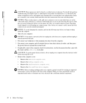
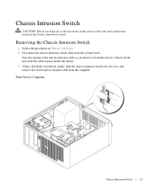
... the routing of the chassis intrusion cable as you begin any of its slot, and remove the switch and its attached cable from the computer. Mini Tower Computer Chassis Intrusion Switch 21
... the routing of the chassis intrusion cable as you begin any of its slot, and remove the switch and its attached cable from the computer. Mini Tower Computer Chassis Intrusion Switch 21

User Guide
Page 26
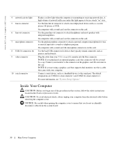
... The power light illuminates and blinks or remains solid to attach a microphone. 26 Mini Tower Computer NOTICE: If your operating system has ACPI enabled, when you troubleshoot problems with ... (see "System Setup" for devices that a LAN (network) connection is in the Windows Device Manager. See "Diagnostic Lights" for devices that you use the keyboard or the ...use the back USB connectors for a description of speakers. Instead, perform an operating system shutdown. www.dell.com | support.dell.com 1 CD/DVD drive 2 floppy drive 3 USB 2.0 connectors (2) 4 LAN indicator light 5...
... The power light illuminates and blinks or remains solid to attach a microphone. 26 Mini Tower Computer NOTICE: If your operating system has ACPI enabled, when you troubleshoot problems with ... (see "System Setup" for devices that a LAN (network) connection is in the Windows Device Manager. See "Diagnostic Lights" for devices that you use the keyboard or the ...use the back USB connectors for a description of speakers. Instead, perform an operating system shutdown. www.dell.com | support.dell.com 1 CD/DVD drive 2 floppy drive 3 USB 2.0 connectors (2) 4 LAN indicator light 5...

User Guide
Page 28
...to the 115-V position even though the AC power available in your location. 4 power connector 5 back-panel connectors Insert the power cable. www.dell.com | support.dell.com 1 cover release latch 2 padlock ring This latch allows you to lock the computer cover. 3 voltage selection switch Your computer is 100 ...AC power available in Japan is equipped with the AC power available in your location. Back-Panel Connectors 1 2 34 5 6 10 9 7 8 28 Mini Tower Computer NOTICE: The voltage selection switch must be set the switch for any installed PCI and PCI Express cards.
...to the 115-V position even though the AC power available in your location. 4 power connector 5 back-panel connectors Insert the power cable. www.dell.com | support.dell.com 1 cover release latch 2 padlock ring This latch allows you to lock the computer cover. 3 voltage selection switch Your computer is 100 ...AC power available in Japan is equipped with the AC power available in your location. Back-Panel Connectors 1 2 34 5 6 10 9 7 8 28 Mini Tower Computer NOTICE: The voltage selection switch must be set the switch for any installed PCI and PCI Express cards.

User Guide
Page 29
... connector on the back panel of the network cable to ensure reliable operation. 29 Mini Tower Computer It is automatically disabled if the computer detects an installed card containing a parallel connector configured to the parallel connector. www.dell.com | support.dell.com 1 parallel connector Connect a parallel device, such as a printer, to the same address...
... connector on the back panel of the network cable to ensure reliable operation. 29 Mini Tower Computer It is automatically disabled if the computer detects an installed card containing a parallel connector configured to the parallel connector. www.dell.com | support.dell.com 1 parallel connector Connect a parallel device, such as a printer, to the same address...
User Guide
Page 30
... computer. On computers with a sound card, use the connector on the card. Plug the cable from the system board. 30 Mini Tower Computer NOTICE: Be careful when opening the computer cover to attach headphones and most speakers with your VGA-compatible monitor into a sound.... NOTE: If you begin any of network traffic may make this section, follow the safety instructions located in the Product Information Guide. www.dell.com | support.dell.com 4 network activity light 5 line-in connector 6 line-out connector 7 microphone connector 8 USB 2.0 connectors (6) 9 video connector 10 ...
... computer. On computers with a sound card, use the connector on the card. Plug the cable from the system board. 30 Mini Tower Computer NOTICE: Be careful when opening the computer cover to attach headphones and most speakers with your VGA-compatible monitor into a sound.... NOTE: If you begin any of network traffic may make this section, follow the safety instructions located in the Product Information Guide. www.dell.com | support.dell.com 4 network activity light 5 line-in connector 6 line-out connector 7 microphone connector 8 USB 2.0 connectors (6) 9 video connector 10 ...
User Guide
Page 31
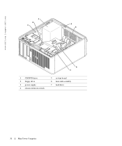
www.dell.com | support.dell.com 3 2 1 4 5 6 7 1 CD/DVD drive 2 floppy drive 3 power supply 4 chassis intrusion switch 5 system board 6 heat sink assembly 7 hard drive 31 Mini Tower Computer
www.dell.com | support.dell.com 3 2 1 4 5 6 7 1 CD/DVD drive 2 floppy drive 3 power supply 4 chassis intrusion switch 5 system board 6 heat sink assembly 7 hard drive 31 Mini Tower Computer

User Guide
Page 33
Mini Tower Computer Mini Tower Computer 33 1 fan connector (FAN) 12 password jumper (PSWD) 2 processor connector (CPU) 13 battery socket (BATT) 3 power connector (12VPOWER) 14 PCI Express x16 connector (SLOT1) 4 ...
Mini Tower Computer Mini Tower Computer 33 1 fan connector (FAN) 12 password jumper (PSWD) 2 processor connector (CPU) 13 battery socket (BATT) 3 power connector (12VPOWER) 14 PCI Express x16 connector (SLOT1) 4 ...

User Guide
Page 34
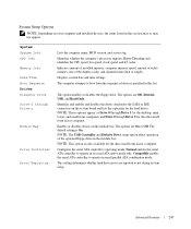
Password features are enabled (default). The real-time clock has not been reset. The real-time clock is being reset (jumpered temporarily). unjumpered 34 Mini Tower Computer www.dell.com | support.dell.com Jumper PSWD Setting RTCRST jumpered Description Password features are disabled.
Password features are enabled (default). The real-time clock has not been reset. The real-time clock is being reset (jumpered temporarily). unjumpered 34 Mini Tower Computer www.dell.com | support.dell.com Jumper PSWD Setting RTCRST jumpered Description Password features are disabled.
User Guide
Page 35
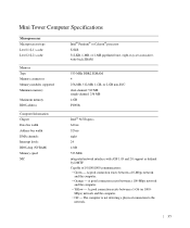
... connection exists between a 100-Mbps network and the computer. • Yellow - Mbps) network and the computer. • Off - A good connection exists between a 1-Gb (or 1000- Mini Tower Computer Specifications Microprocessor Microprocessor type Level 1 (L1) cache Level 2 (L2) cache Memory Type Memory connectors Memory modules supported Minimum memory Maximum memory BIOS address Computer...
... connection exists between a 100-Mbps network and the computer. • Yellow - Mbps) network and the computer. • Off - A good connection exists between a 1-Gb (or 1000- Mini Tower Computer Specifications Microprocessor Microprocessor type Level 1 (L1) cache Level 2 (L2) cache Memory Type Memory connectors Memory modules supported Minimum memory Maximum memory BIOS address Computer...

User Guide
Page 78
... Port Adapter 1 Follow the procedures in place. c Pivot the card retention mechanism upward to secure the adapter bracket in place. www.dell.com | support.dell.com a Place your thumb on the top of the card retention mechanism and grip the bottom of the retention mechanism with the alignment bar...the card or filler bracket fits around the alignment guide. 6 Gently press down on the computer chassis. If you are flush with your mini tower computer also includes two PS/2 connectors. The brackets also keep dust and dirt out of your computer, discharge static electricity from the tab ...
... Port Adapter 1 Follow the procedures in place. c Pivot the card retention mechanism upward to secure the adapter bracket in place. www.dell.com | support.dell.com a Place your thumb on the top of the card retention mechanism and grip the bottom of the retention mechanism with the alignment bar...the card or filler bracket fits around the alignment guide. 6 Gently press down on the computer chassis. If you are flush with your mini tower computer also includes two PS/2 connectors. The brackets also keep dust and dirt out of your computer, discharge static electricity from the tab ...
User Guide
Page 247
... in serial/parallel ATA combination mode. System System Info CPU Info Memory Info Date/Time Boot Sequence Drives Diskette Drive Drive 0 through Drive 3 for the desktop, mini tower, and small form computers and Drive 0 though Drive 5 for the ultra small form factor computer. Indicates amount of installed memory, computer memory speed, amount of...
... in serial/parallel ATA combination mode. System System Info CPU Info Memory Info Date/Time Boot Sequence Drives Diskette Drive Drive 0 through Drive 3 for the desktop, mini tower, and small form computers and Drive 0 though Drive 5 for the ultra small form factor computer. Indicates amount of installed memory, computer memory speed, amount of...

User Guide
Page 254
Mini Tower Computer Desktop Computer 254 Advanced Features NOTICE: This process erases both the system and administrator passwords. 1 Follow the procedures in the Product Information Guide. www.dell.com | support.dell.com Clearing Forgotten Passwords CAUTION: Before you begin any of the procedures in this section, follow the safety instructions located in "Before You Begin." 2 Locate the 2-pin password jumper (PSWD) on the system board, and remove the jumper to clear the password.
Mini Tower Computer Desktop Computer 254 Advanced Features NOTICE: This process erases both the system and administrator passwords. 1 Follow the procedures in the Product Information Guide. www.dell.com | support.dell.com Clearing Forgotten Passwords CAUTION: Before you begin any of the procedures in this section, follow the safety instructions located in "Before You Begin." 2 Locate the 2-pin password jumper (PSWD) on the system board, and remove the jumper to clear the password.

User Guide
Page 263
... all attached devices from the electrical outlet before removing the cover. 5 Remove the computer cover: • Remove the mini tower computer cover. • Remove the desktop computer cover. • Remove the small form factor computer cover. CAUTION: To guard against the electrical shock, always ...locations. 10 Slide the system board assembly toward the front of the computer. Replacing the System Board Removing the System Board: Mini Tower, Desktop, and Small Form Factor Computers 1 Shut down your computer, turn off when you work, periodically touch an unpainted metal surface...
... all attached devices from the electrical outlet before removing the cover. 5 Remove the computer cover: • Remove the mini tower computer cover. • Remove the desktop computer cover. • Remove the small form factor computer cover. CAUTION: To guard against the electrical shock, always ...locations. 10 Slide the system board assembly toward the front of the computer. Replacing the System Board Removing the System Board: Mini Tower, Desktop, and Small Form Factor Computers 1 Shut down your computer, turn off when you work, periodically touch an unpainted metal surface...

User Guide
Page 264
www.dell.com | support.dell.com Mini Tower System Board Screws 1 2 1 mini tower system board 2 screws (10) 264 Replacing the System Board
www.dell.com | support.dell.com Mini Tower System Board Screws 1 2 1 mini tower system board 2 screws (10) 264 Replacing the System Board

User Guide
Page 266
www.dell.com | support.dell.com Small Form Factor System Board Screws 1 2 1 small form factor system board 2 screws (8) Place the system board assembly that you removed from the system board. 4 ... replacement system board to their connectors at the back of the computer. 5 Replace the computer cover. 266 Replacing the System Board Replacing the System Board: Mini Tower, Desktop, and Small Form Factor Computers 1 Gently align the board into the chassis and slide it is identical.
www.dell.com | support.dell.com Small Form Factor System Board Screws 1 2 1 small form factor system board 2 screws (8) Place the system board assembly that you removed from the system board. 4 ... replacement system board to their connectors at the back of the computer. 5 Replace the computer cover. 266 Replacing the System Board Replacing the System Board: Mini Tower, Desktop, and Small Form Factor Computers 1 Gently align the board into the chassis and slide it is identical.
User Guide
Page 267
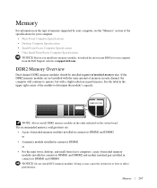
...memory modules installed in connectors DIMM1 and DIMM2 or • A memory module installed in connector DIMM1 or • For the mini tower, desktop, and small form factor computers, a pair of matched memory modules installed in connectors DIMM1 and DIMM2 and another matched pair ...matched memory size. See the label in the upper-right corner of the specifications for your computer: • Mini Tower Computer Specifications • Desktop Computer Specifications • Small Form Factor Computer Specifications • Ultra Small Form Factor Computer Specifications NOTICE: Before you...
...memory modules installed in connectors DIMM1 and DIMM2 or • A memory module installed in connector DIMM1 or • For the mini tower, desktop, and small form factor computers, a pair of matched memory modules installed in connectors DIMM1 and DIMM2 and another matched pair ...matched memory size. See the label in the upper-right corner of the specifications for your computer: • Mini Tower Computer Specifications • Desktop Computer Specifications • Small Form Factor Computer Specifications • Ultra Small Form Factor Computer Specifications NOTICE: Before you...
User Guide
Page 268
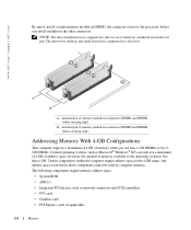
www.dell.com | support.dell.com Be sure to install a single memory module in DIMM1, the connector closest to the processor, before you use four 1-GB DIMMs or two 2GB ... address space: • System ROM • APIC(s) • Integrated PCI devices, such as Microsoft® Windows® XP, can only use a maximum of 4 GB of memory available to the operating system is less than 4 GB. The mini tower, desktop, and small form factor computers have four slots. Certain components within the computer require address space...
www.dell.com | support.dell.com Be sure to install a single memory module in DIMM1, the connector closest to the processor, before you use four 1-GB DIMMs or two 2GB ... address space: • System ROM • APIC(s) • Integrated PCI devices, such as Microsoft® Windows® XP, can only use a maximum of 4 GB of memory available to the operating system is less than 4 GB. The mini tower, desktop, and small form factor computers have four slots. Certain components within the computer require address space...

