
Owner's Manual
Page 10
... system and installs the updates appropriate for your operating system and support for your computer, you use the customized Dell Premier Support website at • Upgrades - If you reinstall the operating system for Dell™ 3.5-inch USB floppy drives, Intel® Pentium® M processors, optical drives, and USB devices. Service call and order...
... system and installs the updates appropriate for your operating system and support for your computer, you use the customized Dell Premier Support website at • Upgrades - If you reinstall the operating system for Dell™ 3.5-inch USB floppy drives, Intel® Pentium® M processors, optical drives, and USB devices. Service call and order...

Owner's Manual
Page 52
...like a translator between the device and any error conditions encountered. Displays error conditions encountered, error codes, and the problem description. The Dell Diagnostics obtains configuration information for more information. Each device has its driver recognizes. Many drivers, such as a printer, mouse, or ... install a new device. 52 Advanced Troubleshooting Displays your Microsoft® Windows® operating system. Drivers What Is a Driver? Dell ships your computer to you to customize the test by changing the test settings. 4 Close the test screen to return to ...
...like a translator between the device and any error conditions encountered. Displays error conditions encountered, error codes, and the problem description. The Dell Diagnostics obtains configuration information for more information. Each device has its driver recognizes. Many drivers, such as a printer, mouse, or ... install a new device. 52 Advanced Troubleshooting Displays your Microsoft® Windows® operating system. Drivers What Is a Driver? Dell ships your computer to you to customize the test by changing the test settings. 4 Close the test screen to return to ...

Owner's Manual
Page 69
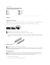
NOTICE: If you remove your original memory modules from the computer during a memory upgrade, keep them separate from any new modules that you may not start properly. Installing Memory CAUTION: Before you touch any of the module with a... instructions located in the connector. Otherwise, your computer may have, even if you purchased the new modules from your computer, discharge static electricity from Dell. notch memory module cutouts (2) crossbar Removing and Installing Parts 67 memory connector closest to components inside your body before you begin any of the memory...
NOTICE: If you remove your original memory modules from the computer during a memory upgrade, keep them separate from any new modules that you may not start properly. Installing Memory CAUTION: Before you touch any of the module with a... instructions located in the connector. Otherwise, your computer may have, even if you purchased the new modules from your computer, discharge static electricity from Dell. notch memory module cutouts (2) crossbar Removing and Installing Parts 67 memory connector closest to components inside your body before you begin any of the memory...

Owner's Manual
Page 79
... cable-to the back of the drive and to the connectors labeled "SATA0" or "SATA1" on the system board. See the drive documentation in your upgrade kit for information on configuring devices for the cable select setting. CD/DVD drive(s) FlexBay for optional floppy drive or Media Card Reader hard drive...
... cable-to the back of the drive and to the connectors labeled "SATA0" or "SATA1" on the system board. See the drive documentation in your upgrade kit for information on configuring devices for the cable select setting. CD/DVD drive(s) FlexBay for optional floppy drive or Media Card Reader hard drive...
Service Manual
Page 14
... other connectors. If possible, do so by your computer, see "Specifications." Otherwise, your original memory modules from the computer during a memory upgrade, keep them separate from any new modules that you may not start properly. l Be sure to install a single memory module in DIMM... begin any of the memory module connector. NOTICE: To prevent static damage to Contents Page Removing and Installing Parts Dell™ Dimension™ 3100/E310 Service Manual Memory Cards Drive Panels Drives Hard Drive Floppy Drive Media Card Reader CD/DVD Drive Processor System Board Power...
... other connectors. If possible, do so by your computer, see "Specifications." Otherwise, your original memory modules from the computer during a memory upgrade, keep them separate from any new modules that you may not start properly. l Be sure to install a single memory module in DIMM... begin any of the memory module connector. NOTICE: To prevent static damage to Contents Page Removing and Installing Parts Dell™ Dimension™ 3100/E310 Service Manual Memory Cards Drive Panels Drives Hard Drive Floppy Drive Media Card Reader CD/DVD Drive Processor System Board Power...

Service Manual
Page 22
... by a silk-screened "1" printed directly on a board or a card is usually indicated by the colored stripe along one connector matches a tab or a filled-in your upgrade kit for information on configuring devices for the cable select setting, the device attached to the last connector on the interface cable is , a notch or...
... by a silk-screened "1" printed directly on a board or a card is usually indicated by the colored stripe along one connector matches a tab or a filled-in your upgrade kit for information on configuring devices for the cable select setting, the device attached to the last connector on the interface cable is , a notch or...

Service Manual
Page 34
.... 4. Leave the release lever extended in the socket. Installing the Processor NOTICE: Ground yourself by sliding the release lever out from Dell, discard the original heat sink. Open the processor cover by touching an unpainted metal surface on the socket. If you are not installing ...a processor upgrade kit from Dell, reuse the original heat sink when you are installing a processor upgrade kit from beneath the center cover latch on the back of the computer. Then, pull the lever...
.... 4. Leave the release lever extended in the socket. Installing the Processor NOTICE: Ground yourself by sliding the release lever out from Dell, discard the original heat sink. Open the processor cover by touching an unpainted metal surface on the socket. If you are not installing ...a processor upgrade kit from Dell, reuse the original heat sink when you are installing a processor upgrade kit from beneath the center cover latch on the back of the computer. Then, pull the lever...

Service Manual
Page 35
... cover latch NOTICE: To avoid damage, ensure that the heat sink is correctly seated and secure. If you installed a processor replacement kit from Dell, reuse the original heat sink assembly when you turn on the socket. 7. If the release lever on the socket is positioned underneath the center...and rear alignment notches on the processor with the socket, and do not use excessive force when you are not installing a processor upgrade kit from Dell, return the original heat sink assembly and processor to secure the processor. 1. Align the pin-1 corners of the processor.
... cover latch NOTICE: To avoid damage, ensure that the heat sink is correctly seated and secure. If you installed a processor replacement kit from Dell, reuse the original heat sink assembly when you turn on the socket. 7. If the release lever on the socket is positioned underneath the center...and rear alignment notches on the processor with the socket, and do not use excessive force when you are not installing a processor upgrade kit from Dell, return the original heat sink assembly and processor to secure the processor. 1. Align the pin-1 corners of the processor.


