
Owner's Manual
Page 1
Dell™ Dimension™ 5000 Service Tag CD or DVD eject button CD or DVD activity light FlexBay for optional floppy drive or Media Card Reader microphone connector headphone connector diagnostic lights hard drive activity light power button USB 2.0 connectors (2) cover latch release power connector sound-card connectors card slots for PCI Express x16 (1), PCI (2), PCI Express x1 (1) USB 2.0 connectors (5) network adapter VGA video connector (integrated) serial connector parallel connector Model DCSM www.dell.com | support.dell.com
Dell™ Dimension™ 5000 Service Tag CD or DVD eject button CD or DVD activity light FlexBay for optional floppy drive or Media Card Reader microphone connector headphone connector diagnostic lights hard drive activity light power button USB 2.0 connectors (2) cover latch release power connector sound-card connectors card slots for PCI Express x16 (1), PCI (2), PCI Express x1 (1) USB 2.0 connectors (5) network adapter VGA video connector (integrated) serial connector parallel connector Model DCSM www.dell.com | support.dell.com

Owner's Manual
Page 3
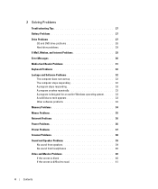
... 21 Connecting a TV 21 Changing the Display Settings 22 Setting Up a Home and Office Network 22 Connecting to a Network Adapter 22 Network Setup Wizard 23 Power Management 23 Standby Mode 23 Hibernate Mode 24 Power Options Properties 24 Hyper-Threading 26 Contents 3
... 21 Connecting a TV 21 Changing the Display Settings 22 Setting Up a Home and Office Network 22 Connecting to a Network Adapter 22 Network Setup Wizard 23 Power Management 23 Standby Mode 23 Hibernate Mode 24 Power Options Properties 24 Hyper-Threading 26 Contents 3
Owner's Manual
Page 4
... for an earlier Windows operating system. . . . . 33 A solid blue screen appears 33 Other software problems 34 Memory Problems 34 Mouse Problems 35 Network Problems 36 Power Problems 36 Printer Problems 37 Scanner Problems 38 Sound and Speaker Problems 39 No sound from speakers 39 No sound from headphones 40 Video and...
... for an earlier Windows operating system. . . . . 33 A solid blue screen appears 33 Other software problems 34 Memory Problems 34 Mouse Problems 35 Network Problems 36 Power Problems 36 Printer Problems 37 Scanner Problems 38 Sound and Speaker Problems 39 No sound from speakers 39 No sound from headphones 40 Video and...

Owner's Manual
Page 6
... Replacing the Drive-Panel Insert 77 Replacing the Drive Panel 78 Drives 79 IDE Drive Addressing 79 Connecting Drive Cables 80 Drive Interface Connectors 80 Power Cable Connector 80 Connecting and Disconnecting Drive Cables 81 Hard Drive 81 Removing a Hard Drive 82 Installing a Hard Drive 83 Adding a Second Hard Drive 84...
... Replacing the Drive-Panel Insert 77 Replacing the Drive Panel 78 Drives 79 IDE Drive Addressing 79 Connecting Drive Cables 80 Drive Interface Connectors 80 Power Cable Connector 80 Connecting and Disconnecting Drive Cables 81 Hard Drive 81 Removing a Hard Drive 82 Installing a Hard Drive 83 Adding a Second Hard Drive 84...
Owner's Manual
Page 23
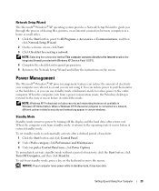
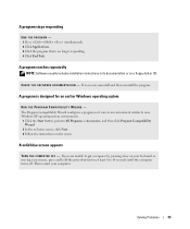
...the Start button and click Control Panel. 2 Under Pick a category, click Performance and Maintenance. 3 Under or pick a Control Panel icon, click Power Options. NOTE: Windows XP Professional includes security and networking features not available in a home or small office. 1 Click the Start button, point to ...Windows® XP operating system provides a Network Setup Wizard to guide you can use standby mode or hibernate mode to reduce power to the entire computer. NOTE: Selecting the connection method This computer connects directly to the Internet enables the integrated firewall provided with...
...the Start button and click Control Panel. 2 Under Pick a category, click Performance and Maintenance. 3 Under or pick a Control Panel icon, click Power Options. NOTE: Windows XP Professional includes security and networking features not available in a home or small office. 1 Click the Start button, point to ...Windows® XP operating system provides a Network Setup Wizard to guide you can use standby mode or hibernate mode to reduce power to the entire computer. NOTE: Selecting the connection method This computer connects directly to the Internet enables the integrated firewall provided with...

Owner's Manual
Page 24
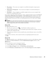
... mode. Each scheme has different settings for each scheme appear in hibernate mode. Power Options Properties Define your hibernate settings on the Power Schemes tab, Advanced tab, and Hibernate tab. www.dell.com | support.dell.com Hibernate Mode Hibernate mode conserves power by copying system data to select one of the standard Windows schemes installed...
... mode. Each scheme has different settings for each scheme appear in hibernate mode. Power Options Properties Define your hibernate settings on the Power Schemes tab, Advanced tab, and Hibernate tab. www.dell.com | support.dell.com Hibernate Mode Hibernate mode conserves power by copying system data to select one of the standard Windows schemes installed...
Owner's Manual
Page 25
...want to time-out before the hard drive. To program these functions, click an option from batteries for the changed scheme. For more information on power management options: 1 Click the Start button and click Help and Support. 2 In the Help and Support window, click Performance and maintenance. 3...hard disks, System stand by, or System hibernates field, and then select a timeout from standby mode or hibernate mode. • Program the power button to be locked up. If your computer is a portable computer and you set the monitor to change the default settings for your Windows...
...want to time-out before the hard drive. To program these functions, click an option from batteries for the changed scheme. For more information on power management options: 1 Click the Start button and click Help and Support. 2 In the Help and Support window, click Performance and maintenance. 3...hard disks, System stand by, or System hibernates field, and then select a timeout from standby mode or hibernate mode. • Program the power button to be locked up. If your computer is a portable computer and you set the monitor to change the default settings for your Windows...

Owner's Manual
Page 32
... the cable connector for bent or broken pins and for at least 8 to 10 seconds until the computer turns off. www.dell.com | support.dell.com Keyboard Problems CAUTION: Before you begin any of the procedures in this section, follow the safety instructions located in the Product... Information Guide. Then restart your mouse, press and hold the power button for damaged or frayed cables. Straighten bent pins. • Remove...
... the cable connector for bent or broken pins and for at least 8 to 10 seconds until the computer turns off. www.dell.com | support.dell.com Keyboard Problems CAUTION: Before you begin any of the procedures in this section, follow the safety instructions located in the Product... Information Guide. Then restart your mouse, press and hold the power button for damaged or frayed cables. Straighten bent pins. • Remove...
Owner's Manual
Page 33
A program is no longer responding. 4 Click End Task. Then restart your mouse, press and hold the power button for an earlier Windows operating system RUN THE PROGRAM COMPATIBILITY WIZARD - A solid blue screen appears TU R N T H E C O M P U T E R O F F - A program stops responding END THE PROGRAM - 1 Press simultaneously. 2 ...
A program is no longer responding. 4 Click End Task. Then restart your mouse, press and hold the power button for an earlier Windows operating system RUN THE PROGRAM COMPATIBILITY WIZARD - A solid blue screen appears TU R N T H E C O M P U T E R O F F - A program stops responding END THE PROGRAM - 1 Press simultaneously. 2 ...

Owner's Manual
Page 36
...I S N O T R E S P O N D I N G G R E E N - www.dell.com | support.dell.com Network Problems CAUTION: Before you begin any of the procedures in this section, follow the safety instructions located in standby ...mode. R U N T H E H A R D W A R E TR O U B L E S H O O T E R - Ensure that indicates no network communication exists. For a description of network lights, see "Controls and Lights" on the keyboard, move the mouse, or press the power...
...I S N O T R E S P O N D I N G G R E E N - www.dell.com | support.dell.com Network Problems CAUTION: Before you begin any of the procedures in this section, follow the safety instructions located in standby ...mode. R U N T H E H A R D W A R E TR O U B L E S H O O T E R - Ensure that indicates no network communication exists. For a description of network lights, see "Controls and Lights" on the keyboard, move the mouse, or press the power...
Owner's Manual
Page 37
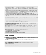
... in this section, follow the safety instructions located in the Product Information Guide. A device might exist. • Ensure that the processor power cable is set to the system board (see page 61). NOTE: If you begin any cards (see page 65). • Remove ...it with another device, such as a lamp. • Ensure that the power strip is not receiving power. • Reseat the power cable into both the power connector on . Also bypass power protection devices, power strips, and power extension cables to the same electrical outlet Printer Problems CAUTION: Before you need ...
... in this section, follow the safety instructions located in the Product Information Guide. A device might exist. • Ensure that the processor power cable is set to the system board (see page 61). NOTE: If you begin any cards (see page 65). • Remove ...it with another device, such as a lamp. • Ensure that the power strip is not receiving power. • Reseat the power cable into both the power connector on . Also bypass power protection devices, power strips, and power extension cables to the same electrical outlet Printer Problems CAUTION: Before you need ...

Owner's Manual
Page 40
www.dell.com | support.dell.com R E I N S T A L L T H E S O U N D D R I N D O W S V O L U M E C O N T R O L - See page 49. A D J U S T T H E W I V E R - C H E C K T H E D I A G N O S T I C L I C A L O U T L E T - See page 43. 40 Solving Problems See page 49. ... setup diagram for bent or broken pins. (It is blinking, press a key on . Ensure that the electrical outlet is lit or blinking, the monitor has power. No sound from headphones C H E C K T H E H E A D P H O N E C A B L E C O N N E C T I G H T - Ensure that the sound is securely inserted into the headphone ...
www.dell.com | support.dell.com R E I N S T A L L T H E S O U N D D R I N D O W S V O L U M E C O N T R O L - See page 49. A D J U S T T H E W I V E R - C H E C K T H E D I A G N O S T I C L I C A L O U T L E T - See page 43. 40 Solving Problems See page 49. ... setup diagram for bent or broken pins. (It is blinking, press a key on . Ensure that the electrical outlet is lit or blinking, the monitor has power. No sound from headphones C H E C K T H E H E A D P H O N E C A B L E C O N N E C T I G H T - Ensure that the sound is securely inserted into the headphone ...

Owner's Manual
Page 43
... starts normally, all four lights go off , plug it into a working electrical outlet and press the power button. Suggested Resolution None. • The computer is in a normal on the front panel (see page 118). Contact Dell (see page 55). Troubleshooting Tools Diagnostic Lights CAUTION: Before you troubleshoot a problem, your computer has four...
... starts normally, all four lights go off , plug it into a working electrical outlet and press the power button. Suggested Resolution None. • The computer is in a normal on the front panel (see page 118). Contact Dell (see page 55). Troubleshooting Tools Diagnostic Lights CAUTION: Before you troubleshoot a problem, your computer has four...

Owner's Manual
Page 44
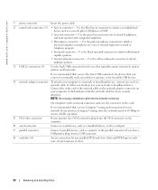
...• If the problem persists, contact Dell (see page 63), and then restart the computer. Reinstall all power and data cables and restart the computer. • If the problem persists, contact Dell (see page 118). www.dell.com | support.dell.com Light Pattern Problem Description Suggested Resolution... graphics card that you know works and restart the computer. • If the problem persists or the computer has integrated graphics, contact Dell (see page 118). A possible floppy or hard drive failure has occurred. A possible USB failure has occurred. If the computer starts ...
...• If the problem persists, contact Dell (see page 63), and then restart the computer. Reinstall all power and data cables and restart the computer. • If the problem persists, contact Dell (see page 118). www.dell.com | support.dell.com Light Pattern Problem Description Suggested Resolution... graphics card that you know works and restart the computer. • If the problem persists or the computer has integrated graphics, contact Dell (see page 118). A possible floppy or hard drive failure has occurred. A possible USB failure has occurred. If the computer starts ...

Owner's Manual
Page 53
... losing data, save and close any open files and exit any open programs before you shut down your operating system, press and hold the power button for removing and installing the components in your computer. 1 Shut down the operating system: a Save and close any open files, exit... Turn Off Computer. Removing and Installing Parts 53 b In the Turn off computer window, click Turn off when you turn off . If your Dell™ Product Information Guide. • A component can be replaced or-if purchased separately-installed by performing the removal procedure in your computer and...
... losing data, save and close any open files and exit any open programs before you shut down your operating system, press and hold the power button for removing and installing the components in your computer. 1 Shut down the operating system: a Save and close any open files, exit... Turn Off Computer. Removing and Installing Parts 53 b In the Turn off computer window, click Turn off when you turn off . If your Dell™ Product Information Guide. • A component can be replaced or-if purchased separately-installed by performing the removal procedure in your computer and...

Owner's Manual
Page 54
... guidelines to help protect your computer from their electrical outlets, and then press the power button to ground the system board. Damage due to dissipate any static electricity that is not authorized by Dell is not covered by your computer. As you work, periodically touch an unpainted metal... from the computer. 3 Disconnect your computer and all attached devices from potential damage and to avoid bending any connector pins. www.dell.com | support.dell.com Before Working Inside Your Computer Use the following steps before you begin any of the procedures in this type of cable, press...
... guidelines to help protect your computer from their electrical outlets, and then press the power button to ground the system board. Damage due to dissipate any static electricity that is not authorized by Dell is not covered by your computer. As you work, periodically touch an unpainted metal... from the computer. 3 Disconnect your computer and all attached devices from potential damage and to avoid bending any connector pins. www.dell.com | support.dell.com Before Working Inside Your Computer Use the following steps before you begin any of the procedures in this type of cable, press...

Owner's Manual
Page 56
... and most kinds of the vents. Use the headphone connector to the system. Use the lights to identify your computer when you use the power button to ensure that you troubleshoot a computer problem based on when the computer reads data from or writes data to a USB device). For...ventilated. For adequate cooling, do not use the back USB connectors for devices that the system is operating. NOTICE: Ensure that you access the Dell Support website or call technical support. 56 Removing and Installing Parts Press to remove the cover. Use the microphone connector to eject a disk ...
... and most kinds of the vents. Use the headphone connector to the system. Use the lights to identify your computer when you use the power button to ensure that you troubleshoot a computer problem based on when the computer reads data from or writes data to a USB device). For...ventilated. For adequate cooling, do not use the back USB connectors for devices that the system is operating. NOTICE: Ensure that you access the Dell Support website or call technical support. 56 Removing and Installing Parts Press to remove the cover. Use the microphone connector to eject a disk ...
Owner's Manual
Page 58
... the connector on your network or broadband device. Use the yellow subwoofer connector to the network adapter connector on the card. www.dell.com | support.dell.com 1 power connector Insert the power cable. 2 sound card connectors (5) • Line-in connector to attach a record/playback device such as joysticks or cameras, or for any installed...
... the connector on your network or broadband device. Use the yellow subwoofer connector to the network adapter connector on the card. www.dell.com | support.dell.com 1 power connector Insert the power cable. 2 sound card connectors (5) • Line-in connector to attach a record/playback device such as joysticks or cameras, or for any installed...

Owner's Manual
Page 60
Follow the procedures in "Before You Begin" on all computers. 60 Removing and Installing Parts power supply system board CD or DVD drive *floppy drive hard drive *May not be present on page 53. www.dell.com | support.dell.com 4 Locate the three hinge tabs on the bottom edge of the computer. 5 Grip the...
Follow the procedures in "Before You Begin" on all computers. 60 Removing and Installing Parts power supply system board CD or DVD drive *floppy drive hard drive *May not be present on page 53. www.dell.com | support.dell.com 4 Locate the three hinge tabs on the bottom edge of the computer. 5 Grip the...
Owner's Manual
Page 61
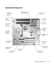
System Board Components memory module connectors (1, 2, 3, 4) processor power connector processor and heat sink connector SATA connectors (2) (SATA-0, SATA-2) floppy drive connector (FLOPPY) fan connector (CPU FAN) battery socket (BATTERY) serial PS/2 connector PCI card connectors front panel I/O connector main power connector IDE drive connector clear CMOS jumper (RTCRST) password jumper (PSWD) FlexBay USB connector PCI Express x16 card connector PCI Express x1 card connector Removing and Installing Parts 61
System Board Components memory module connectors (1, 2, 3, 4) processor power connector processor and heat sink connector SATA connectors (2) (SATA-0, SATA-2) floppy drive connector (FLOPPY) fan connector (CPU FAN) battery socket (BATTERY) serial PS/2 connector PCI card connectors front panel I/O connector main power connector IDE drive connector clear CMOS jumper (RTCRST) password jumper (PSWD) FlexBay USB connector PCI Express x16 card connector PCI Express x1 card connector Removing and Installing Parts 61


