Manual
Page 17
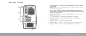
...other devices into the security cable slot on your computer. 2 Latch - Access connectors for any installed PCI and PCI Express cards. 5 Power connector - Indicates if the power supply is in working condition. 7 Diagnostic button - Back View Features 1 2 3 4 5 67 1 Security cable slot - Slide the latch... to the right to open the security lock slot and to the computer. Connects to the power cable. 6 Diagnostic light - For more ...
...other devices into the security cable slot on your computer. 2 Latch - Access connectors for any installed PCI and PCI Express cards. 5 Power connector - Indicates if the power supply is in working condition. 7 Diagnostic button - Back View Features 1 2 3 4 5 67 1 Security cable slot - Slide the latch... to the right to open the security lock slot and to the computer. Connects to the power cable. 6 Diagnostic light - For more ...

Manual
Page 55
...electrical outlet is known to be a problem with the computer. For further assistance, contact Alienware support (see "Back View Features" on page 17) . • If the diagnostic light turns ON, the power supply is functioning as a radio or lamp that the computer is properly connected to the surge... the diagnostic light (to locate the diagnostic button and diagnostic light, see "CONTACTING ALIENWARE" on the computer are properly connected to your computer and that is not working . Power When you press the power button, the computer does not turn ON, there may be working , contact an...
...electrical outlet is known to be a problem with the computer. For further assistance, contact Alienware support (see "Back View Features" on page 17) . • If the diagnostic light turns ON, the power supply is functioning as a radio or lamp that the computer is properly connected to the surge... the diagnostic light (to locate the diagnostic button and diagnostic light, see "CONTACTING ALIENWARE" on the computer are properly connected to your computer and that is not working . Power When you press the power button, the computer does not turn ON, there may be working , contact an...
Service Manual
Page 4
... 48 Replacing the Processor Liquid-Cooling Assembly 49 CHAPTER 10: PROCESSOR 50 Removing the Processor 52 Replacing the Processor 53 CHAPTER 11: POWER SUPPLY 55 Removing the Power Supply 57 Replacing the Power Supply 59 CHAPTER 12: BATTERY 60 Removing the Coin-Cell Battery 62 Replacing the Coin-Cell Battery 63 Removing the Theater-Lighting Batteries...
... 48 Replacing the Processor Liquid-Cooling Assembly 49 CHAPTER 10: PROCESSOR 50 Removing the Processor 52 Replacing the Processor 53 CHAPTER 11: POWER SUPPLY 55 Removing the Power Supply 57 Replacing the Power Supply 59 CHAPTER 12: BATTERY 60 Removing the Coin-Cell Battery 62 Replacing the Coin-Cell Battery 63 Removing the Theater-Lighting Batteries...

Service Manual
Page 55
CHAPTER 10: POWER SUPPLY CHAPTER 11: POWER SUPPLY CHAPTER 11: POWER SUPPLY 055 /055
CHAPTER 10: POWER SUPPLY CHAPTER 11: POWER SUPPLY CHAPTER 11: POWER SUPPLY 055 /055

Service Manual
Page 56
...brackets, front-panel inserts, etc.) removed. For additional safety best practices information, see the Regulatory Compliance Homepage at www.dell.com/regulatory_compliance. CHAPTER 11: POWER SUPPLY 056 /056 WARNING: To guard against electrical shock, always unplug your computer. CAUTION: Only a certified service technician should... before removing the side panel(s). WARNING: Do not operate your computer with your computer. Power Supply WARNING: Before working inside your computer, read the safety information that is not authorized by Dell™ is not covered by your warranty.
...brackets, front-panel inserts, etc.) removed. For additional safety best practices information, see the Regulatory Compliance Homepage at www.dell.com/regulatory_compliance. CHAPTER 11: POWER SUPPLY 056 /056 WARNING: To guard against electrical shock, always unplug your computer. CAUTION: Only a certified service technician should... before removing the side panel(s). WARNING: Do not operate your computer with your computer. Power Supply WARNING: Before working inside your computer, read the safety information that is not authorized by Dell™ is not covered by your warranty.
Service Manual
Page 57
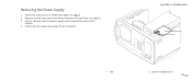
CHAPTER 11: POWER SUPPLY 2 1 1 tab 2 power-supply cover 057 /057 Lift the tab and slide the power-supply cover towards the back of the chassis. 4. Removing the Power Supply 1. Lift the power-supply cover away from the chassis. Remove the left side-panel (see "Removing the Left Side-Panel" on page 6. 2. Follow the instructions in "Before You Begin" on page 11). 3.
CHAPTER 11: POWER SUPPLY 2 1 1 tab 2 power-supply cover 057 /057 Lift the tab and slide the power-supply cover towards the back of the chassis. 4. Removing the Power Supply 1. Lift the power-supply cover away from the chassis. Remove the left side-panel (see "Removing the Left Side-Panel" on page 6. 2. Follow the instructions in "Before You Begin" on page 11). 3.

Service Manual
Page 58
CHAPTER 11: POWER SUPPLY 8. Remove the bezel from the power supply. 6. Loosen the four captive screws that secure the power supply to the back of the chassis. Slide the power supply through the back of the chassis. 7. Remove the four screws that secure the power supply to the bezel. 9. Disconnect the DC wire harness and the AC power cable from the power supply. 1 1 power supply 1 2 2 captive screws (4) 1 bezel 3 screws (4) 2 3 2 power supply 058 /058 5.
CHAPTER 11: POWER SUPPLY 8. Remove the bezel from the power supply. 6. Loosen the four captive screws that secure the power supply to the back of the chassis. Slide the power supply through the back of the chassis. 7. Remove the four screws that secure the power supply to the bezel. 9. Disconnect the DC wire harness and the AC power cable from the power supply. 1 1 power supply 1 2 2 captive screws (4) 1 bezel 3 screws (4) 2 3 2 power supply 058 /058 5.

Service Manual
Page 59
... them on page 6. 2. Replace the four screws that secure the power supply to the bezel. 3. CHAPTER 11: POWER SUPPLY 059 /059 Connect your computer and devices to the power supply. 6. Slide the power supply into the chassis through the back of the chassis. 5. Align the tabs on the power-supply cover with the slots on page 11). 9. Replace the left...
... them on page 6. 2. Replace the four screws that secure the power supply to the bezel. 3. CHAPTER 11: POWER SUPPLY 059 /059 Connect your computer and devices to the power supply. 6. Slide the power supply into the chassis through the back of the chassis. 5. Align the tabs on the power-supply cover with the slots on page 11). 9. Replace the left...

Service Manual
Page 79
... right side-panel(s) to the chassis. 1 screws (3) CHAPTER 16: RIGHT SIDE-PANEL(S) 1 079 /079 Remove the power-supply cover (see "Removing the Left Side-Panel" on page 57). 6. Remove the left side-panel (see "Removing the Power Supply" on page 11). 3. Remove the drive-bay shroud (see "Removing the Drive-Bay Shroud" on page 6. 2.
... right side-panel(s) to the chassis. 1 screws (3) CHAPTER 16: RIGHT SIDE-PANEL(S) 1 079 /079 Remove the power-supply cover (see "Removing the Left Side-Panel" on page 57). 6. Remove the left side-panel (see "Removing the Power Supply" on page 11). 3. Remove the drive-bay shroud (see "Removing the Drive-Bay Shroud" on page 6. 2.
Service Manual
Page 81
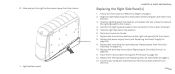
... from the chassis. 1 right bottom-panel CHAPTER 16: RIGHT SIDE-PANEL(S) Replacing the Right Side-Panel(s) 1. Close the PCI shroud (see "Replacing the Power Supply" on 1 page 59). 9. Align the right bottom-panel to the bottom of the computer and slide it into position. 6. Place the chassis on .... 081 /081 Replace the power-supply cover (see "Closing the PCI Shroud" on page 19). 11. Replace the left side-panel (see "Replacing the Drive-Bay Shroud" on page...
... from the chassis. 1 right bottom-panel CHAPTER 16: RIGHT SIDE-PANEL(S) Replacing the Right Side-Panel(s) 1. Close the PCI shroud (see "Replacing the Power Supply" on 1 page 59). 9. Align the right bottom-panel to the bottom of the computer and slide it into position. 6. Place the chassis on .... 081 /081 Replace the power-supply cover (see "Closing the PCI Shroud" on page 19). 11. Replace the left side-panel (see "Replacing the Drive-Bay Shroud" on page...

Service Manual
Page 95
... from the chassis. 1 screws (2) CHAPTER 19: BACK BEZEL 1 2 2 security lock panel 095 /095 Remove the power supply (see "Removing the Processor Liquid-Cooling Assembly" on page 57). Remove the processor liquid-cooling assembly (see "Removing the Power Supply" on page 48). 5. Remove the two screws that it has had sufficient time to the chassis. 6.
... from the chassis. 1 screws (2) CHAPTER 19: BACK BEZEL 1 2 2 security lock panel 095 /095 Remove the power supply (see "Removing the Processor Liquid-Cooling Assembly" on page 57). Remove the processor liquid-cooling assembly (see "Removing the Power Supply" on page 48). 5. Remove the two screws that it has had sufficient time to the chassis. 6.

Service Manual
Page 97
... page 11). 9. Align the tabs on the back bezel with the slots on page 49). 7. Push the back bezel into place. 4. Replace the power supply (see "Replacing the Left Side-Panel" on page 59). 8. Replace the two screws that secure the security lock panel to the chassis. 6. Connect your computer ...
... page 11). 9. Align the tabs on the back bezel with the slots on page 49). 7. Push the back bezel into place. 4. Replace the power supply (see "Replacing the Left Side-Panel" on page 59). 8. Replace the two screws that secure the security lock panel to the chassis. 6. Connect your computer ...


