
Manual
Page 24
... use thermal controls to control the thermal and venting capabilities of your computer by changing the fan speed and behavior of hard drives required varies depending on your Alienware computer's power management controls to help increase energy efficiency. NOTE: RAID requires multiple hard drives.... To access the Command Center, click Start → All Programs→ Alienware→ Command Center→ Command Center. There are four basic RAID levels discussed in this section. • RAID level 0 is recommended...
... use thermal controls to control the thermal and venting capabilities of your computer by changing the fan speed and behavior of hard drives required varies depending on your Alienware computer's power management controls to help increase energy efficiency. NOTE: RAID requires multiple hard drives.... To access the Command Center, click Start → All Programs→ Alienware→ Command Center→ Command Center. There are four basic RAID levels discussed in this section. • RAID level 0 is recommended...

Manual
Page 64
... work surface. • Only operate the computer using the power source type indicated on the rating label. • Never block or cover any openings or fans in the documentation before operating your computer. • Retain all safety and operating instructions. • Never use . • Do not attempt to remove peripheral cards...
... work surface. • Only operate the computer using the power source type indicated on the rating label. • Never block or cover any openings or fans in the documentation before operating your computer. • Retain all safety and operating instructions. • Never use . • Do not attempt to remove peripheral cards...
Service Manual
Page 4
... Removing the Hard-Drive Fan Assembly 42 Replacing the Hard-Drive Fan Assembly 43 Removing the PCI-Fan Assembly 44 Replacing the PCI-Fan Assembly 45 CHAPTER 9: PROCESSOR LIQUID-COOLING ASSEMBLY 46 Removing the Processor Liquid-Cooling Assembly 48 Replacing the Processor Liquid-Cooling Assembly 49 CHAPTER 10: PROCESSOR ...
... Removing the Hard-Drive Fan Assembly 42 Replacing the Hard-Drive Fan Assembly 43 Removing the PCI-Fan Assembly 44 Replacing the PCI-Fan Assembly 45 CHAPTER 9: PROCESSOR LIQUID-COOLING ASSEMBLY 46 Removing the Processor Liquid-Cooling Assembly 48 Replacing the Processor Liquid-Cooling Assembly 49 CHAPTER 10: PROCESSOR ...

Service Manual
Page 10
... additional safety best practices information, see the Regulatory Compliance Homepage at www.dell.com/regulatory_compliance. Left Side-Panel WARNING: Before working inside your computer, read the safety information that is not authorized by Dell™ is not covered by moving fan blades, or other unexpected injuries, always unplug your computer from the electrical...
... additional safety best practices information, see the Regulatory Compliance Homepage at www.dell.com/regulatory_compliance. Left Side-Panel WARNING: Before working inside your computer, read the safety information that is not authorized by Dell™ is not covered by moving fan blades, or other unexpected injuries, always unplug your computer from the electrical...
Service Manual
Page 14
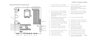
...fan connector (MB_CPU_FAN) 4 memory-module connector (DIMM2) (Aurora and Aurora ALX ) memory-module connector (DIMM3) (Aurora-R2) 5 memory-module connector (DIMM1) 6 memory-module connector (DIMM4) 7 memory-module connector (DIMM3) (Aurora and Aurora ALX) memory-module connector (DIMM2) (Aurora-R2) 8 memory-module connector (DIMM6) (Aurora and Aurora ALX only) 9 memory-module connector (DIMM5) (Aurora and Aurora...) 12 21 PCI-Express x1 connector (SLOT4) 22 S/PDIF connector (SPDIF) 13 (Aurora and Aurora ALX only) 14 23 front audio connector (FRONT AUDIO) 24 PCI-Express x16 connector ...
...fan connector (MB_CPU_FAN) 4 memory-module connector (DIMM2) (Aurora and Aurora ALX ) memory-module connector (DIMM3) (Aurora-R2) 5 memory-module connector (DIMM1) 6 memory-module connector (DIMM4) 7 memory-module connector (DIMM3) (Aurora and Aurora ALX) memory-module connector (DIMM2) (Aurora-R2) 8 memory-module connector (DIMM6) (Aurora and Aurora ALX only) 9 memory-module connector (DIMM5) (Aurora and Aurora...) 12 21 PCI-Express x1 connector (SLOT4) 22 S/PDIF connector (SPDIF) 13 (Aurora and Aurora ALX only) 14 23 front audio connector (FRONT AUDIO) 24 PCI-Express x16 connector ...

Service Manual
Page 15
...) 3 active-vent connector (ACTIVE_VENT) 4 AlienHead connector (HEAD1) 5 front-bezel right connector (FRONT_RIGHT) 6 front-bezel left connector (FRONT_LEFT) 7 PCI-fan connector (FAN_PCI) 12 8 left side-panel contact board connector (SIDE_L) 13 9 power-select connector (PWR_SEL) 10 Bluetooth® connector (BLUETOOTH) 14 ... (HDD_LED2) 15 USB connector (MB_USB) 16 main-power connector (PWR1) 16 17 system-board lighting (MB_MIO) 18 hard-drive fan connector (FAN_HDD) 19 right side-panel connector 20 vent-motor connector (SIDE_R) (VENT_MOTOR1) 21 vent sensors (VENT_SW) 22 ODD ...
...) 3 active-vent connector (ACTIVE_VENT) 4 AlienHead connector (HEAD1) 5 front-bezel right connector (FRONT_RIGHT) 6 front-bezel left connector (FRONT_LEFT) 7 PCI-fan connector (FAN_PCI) 12 8 left side-panel contact board connector (SIDE_L) 13 9 power-select connector (PWR_SEL) 10 Bluetooth® connector (BLUETOOTH) 14 ... (HDD_LED2) 15 USB connector (MB_USB) 16 main-power connector (PWR1) 16 17 system-board lighting (MB_MIO) 18 hard-drive fan connector (FAN_HDD) 19 right side-panel connector 20 vent-motor connector (SIDE_R) (VENT_MOTOR1) 21 vent sensors (VENT_SW) 22 ODD ...

Service Manual
Page 41
... computer covers, bezels, filler brackets, front-panel inserts, etc.) removed. CHAPTER 8: FANS 041 /041 WARNING: To guard against electrical shock, always unplug your warranty. Fans WARNING: Before working inside your computer, read the safety information that is not authorized by Dell™ is not covered by your computer from the electrical outlet before...
... computer covers, bezels, filler brackets, front-panel inserts, etc.) removed. CHAPTER 8: FANS 041 /041 WARNING: To guard against electrical shock, always unplug your warranty. Fans WARNING: Before working inside your computer, read the safety information that is not authorized by Dell™ is not covered by your computer from the electrical outlet before...

Service Manual
Page 42
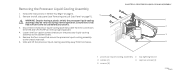
... Side-Panel" on page 11). 3. Remove the left side-panel (see "Opening the PCI Shroud" on page 6. 2. Disconnect the hard-drive fan assembly cable from the connector on page 19). 5. Remove the drive-bay shroud (see "Removing the Drive-Bay Shroud" on the master I/O board. ...CHAPTER 8: FANS 1 2 1 hard-drive fan assembly cable 2 hard-drive fan assembly 042 /042 Follow the instructions in "Before You Begin" on page 18). 4. Make note of the chassis. Lift the ...
... Side-Panel" on page 11). 3. Remove the left side-panel (see "Opening the PCI Shroud" on page 6. 2. Disconnect the hard-drive fan assembly cable from the connector on page 19). 5. Remove the drive-bay shroud (see "Removing the Drive-Bay Shroud" on the master I/O board. ...CHAPTER 8: FANS 1 2 1 hard-drive fan assembly cable 2 hard-drive fan assembly 042 /042 Follow the instructions in "Before You Begin" on page 18). 4. Make note of the chassis. Lift the ...
Service Manual
Page 43
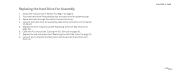
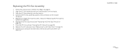
... your computer and devices to the connector on . Replacing the Hard-Drive Fan Assembly 1. Close the PCI shroud (see "Replacing the Drive-Bay Shroud" on page 18). 7. CHAPTER 8: FANS 043 /043 Push the hard-drive fan assembly into the hard-drive fan assembly bay. 3. Route the cable through the slot in "Before You Begin...
... your computer and devices to the connector on . Replacing the Hard-Drive Fan Assembly 1. Close the PCI shroud (see "Replacing the Drive-Bay Shroud" on page 18). 7. CHAPTER 8: FANS 043 /043 Push the hard-drive fan assembly into the hard-drive fan assembly bay. 3. Route the cable through the slot in "Before You Begin...

Service Manual
Page 44
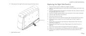
... out of the chassis. Open the PCI shroud (see "Removing the PCI-Express Card(s)" on page 18). 4. CHAPTER 8: FANS 1 2 3 1 PCI-fan assembly cable 3 tabs (2) 2 PCI-fan assembly 044 /044 Disconnect the PCI-fan assembly cable from the connector on page 6. 2. Follow the instructions in "Before You Begin" on the master I/O board. 7. Remove the drive...
... out of the chassis. Open the PCI shroud (see "Removing the PCI-Express Card(s)" on page 18). 4. CHAPTER 8: FANS 1 2 3 1 PCI-fan assembly cable 3 tabs (2) 2 PCI-fan assembly 044 /044 Disconnect the PCI-fan assembly cable from the connector on page 6. 2. Follow the instructions in "Before You Begin" on the master I/O board. 7. Remove the drive...
Service Manual
Page 45
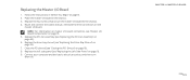
... into the chassis. 4. Replace the drive-bay shroud (see "Closing the PCI Shroud" on . CHAPTER 8: FANS 045 /045 Connect the PCI-fan assembly cable to electrical outlets and then turn them on page 18). 8. Close the PCI shroud (see "Replacing the Drive-Bay Shroud" on page 33). 6. ... connector on page 11). 9. Replace full-length PCI-Express cards, if any (see "Replacing the Left Side-Panel" on the master I/O board. 5. Replacing the PCI-Fan Assembly 1. Follow the instructions in "Before You Begin" on the chassis. 3. Align the PCI...
... into the chassis. 4. Replace the drive-bay shroud (see "Closing the PCI Shroud" on . CHAPTER 8: FANS 045 /045 Connect the PCI-fan assembly cable to electrical outlets and then turn them on page 18). 8. Close the PCI shroud (see "Replacing the Drive-Bay Shroud" on page 33). 6. ... connector on page 11). 9. Replace full-length PCI-Express cards, if any (see "Replacing the Left Side-Panel" on the master I/O board. 5. Replacing the PCI-Fan Assembly 1. Follow the instructions in "Before You Begin" on the chassis. 3. Align the PCI...
Service Manual
Page 48
... screws that secure the processor liquid-cooling assembly to the system board. 5. Slide and lift the processor liquid-cooling assembly away from the connectors (SYS FAN and CPU PUMP) on the top-lighting board. 4. WARNING: Despite having a plastic shield, the processor liquid-cooling assembly may be very hot during normal operation...
... screws that secure the processor liquid-cooling assembly to the system board. 5. Slide and lift the processor liquid-cooling assembly away from the connectors (SYS FAN and CPU PUMP) on the top-lighting board. 4. WARNING: Despite having a plastic shield, the processor liquid-cooling assembly may be very hot during normal operation...

Service Manual
Page 49
... to electrical outlets and then turn them on page 11). 7. Replace the four screws that secure the processor liquid-cooling assembly to the connectors (SYS FAN and CPU PUMP) on the top lighting-board. 6. CHAPTER 9: PROCESSOR LIQUID-COOLING ASSEMBLY 049 /049 Replacing the Processor Liquid-Cooling Assembly 1. Follow the instructions in...
... to electrical outlets and then turn them on page 11). 7. Replace the four screws that secure the processor liquid-cooling assembly to the connectors (SYS FAN and CPU PUMP) on the top lighting-board. 6. CHAPTER 9: PROCESSOR LIQUID-COOLING ASSEMBLY 049 /049 Replacing the Processor Liquid-Cooling Assembly 1. Follow the instructions in...

Service Manual
Page 72
... the connectors on page 19). 5. Removing the Master I /O board to the chassis. 8. Follow the instructions in "Before You Begin" on page 44). 6. Remove the PCI-fan assembly (see "Removing the Drive-Bay Shroud" on the master I /O BOARD 1 072 /072 Remove the four screws that you remove them correctly after installing the... new master I/O board. 7. Remove the drive-bay shroud (see "Removing the PCI-Fan Assembly" on page 6. 2. Note the routing of the chassis. 1 screws (4) CHAPTER 14: MASTER I /O board.
... the connectors on page 19). 5. Removing the Master I /O board to the chassis. 8. Follow the instructions in "Before You Begin" on page 44). 6. Remove the PCI-fan assembly (see "Removing the Drive-Bay Shroud" on the master I /O BOARD 1 072 /072 Remove the four screws that you remove them correctly after installing the... new master I/O board. 7. Remove the drive-bay shroud (see "Removing the PCI-Fan Assembly" on page 6. 2. Note the routing of the chassis. 1 screws (4) CHAPTER 14: MASTER I /O board.
Service Manual
Page 73
... shroud (see "Replacing the Left Side-Panel" on page 15. 5. CHAPTER 14: MASTER I /O Board 1. Close the PCI shroud (see "Replacing the PCI-Fan Assembly" on . Follow the instructions in the chassis. 3. Replace the PCI-fan assembly (see "Closing the PCI Shroud" on page 19). 7. Connect your computer and devices to the chassis. 4.
... shroud (see "Replacing the Left Side-Panel" on page 15. 5. CHAPTER 14: MASTER I /O Board 1. Close the PCI shroud (see "Replacing the PCI-Fan Assembly" on . Follow the instructions in the chassis. 3. Replace the PCI-fan assembly (see "Closing the PCI Shroud" on page 19). 7. Connect your computer and devices to the chassis. 4.

Service Manual
Page 79
Open the PCI shroud (see "Removing the Hard-Drive Fan Assembly" on page 18). 4. Remove the hard-drive fan assembly (see "Opening the PCI Shroud" on page 42). 7. Follow the instructions in "Before You Begin" on page 11). 3. Remove the three screws that secure ...
Open the PCI shroud (see "Removing the Hard-Drive Fan Assembly" on page 18). 4. Remove the hard-drive fan assembly (see "Opening the PCI Shroud" on page 42). 7. Follow the instructions in "Before You Begin" on page 11). 3. Remove the three screws that secure ...
Service Manual
Page 81
... the three screws that secure the lighting board to the chassis. 8. Replace the drive-bay shroud (see "Replacing the Hard-Drive Fan Assembly" on page 19). 11. Replace the hard-drive fan assembly (see "Replacing the Drive-Bay Shroud" on page 43). 10. 13. Place the chassis on the master I/O board. 5. Slide...
... the three screws that secure the lighting board to the chassis. 8. Replace the drive-bay shroud (see "Replacing the Hard-Drive Fan Assembly" on page 19). 11. Replace the hard-drive fan assembly (see "Replacing the Drive-Bay Shroud" on page 43). 10. 13. Place the chassis on the master I/O board. 5. Slide...

Service Manual
Page 104
...board. 13. Remove any PCI-Express cards (see "Removing the Left Side-Panel" on page 44). 6. Remove the drive-bay shroud (see "Removing the PCI-Fan Assembly" on page 11). 3. Remove the top I/O panel. 1 2 1 panel insert 3 screws (4) CHAPTER 21: TOP I/O PANEL 4 3 2 top I /O Panel 1. Remove the... PCI-fan assembly (see "Removing the Drive-Bay Shroud" on page 90). 10. Disconnect the top I /O panel to the chassis. 12. Follow the instructions in "Before You ...
...board. 13. Remove any PCI-Express cards (see "Removing the Left Side-Panel" on page 44). 6. Remove the drive-bay shroud (see "Removing the PCI-Fan Assembly" on page 11). 3. Remove the top I/O panel. 1 2 1 panel insert 3 screws (4) CHAPTER 21: TOP I/O PANEL 4 3 2 top I /O Panel 1. Remove the... PCI-fan assembly (see "Removing the Drive-Bay Shroud" on page 90). 10. Disconnect the top I /O panel to the chassis. 12. Follow the instructions in "Before You ...

Service Manual
Page 105
... the PCI-Express Card(s)" on page 45). 11. Replace the PCI-Express cards (see "Replacing the Left Side-Panel" on page 92). 7. Replace the PCI-fan assembly (see "Replacing the Right Side-Panel(s)" on . 0105 /0105 Replace the right side-panel(s) (see "Replacing the PCI...-Fan Assembly" on page 33). Push the panel insert into position. 6. CHAPTER 21: TOP I /O Panel 1. Connect your computer and devices to the connectors on page 19). ...
... the PCI-Express Card(s)" on page 45). 11. Replace the PCI-Express cards (see "Replacing the Left Side-Panel" on page 92). 7. Replace the PCI-fan assembly (see "Replacing the Right Side-Panel(s)" on . 0105 /0105 Replace the right side-panel(s) (see "Replacing the PCI...-Fan Assembly" on page 33). Push the panel insert into position. 6. CHAPTER 21: TOP I /O Panel 1. Connect your computer and devices to the connectors on page 19). ...


