
Service Manual
Page 5
... 3-5 3.4 Scanner and ADF 3-6 3.4.1 ADF unit 3-6 3.4.2 ADF roller 3-7 3.4.3 OPE Unit 3-8 3.4.4 Platen unit 3-8 3.4.5 CIS unit 3-9 3.5 Middle Cover 3-10 3.6 Fuser Unit 3-12 3.6.1 Whole Fuser Unit 3-12 3.6.2 Main Service parts of Fuser Unit 3-13 3.6.3 Replacing the Main Service part of Fuser Unit 3-15 3.7 LSU 3-22 3.8 Main PBA 3-24 3.9 Drive unit 3-25 3.10 Solenoid 3-26 3.11 FAN 3-26 3.12...
... 3-5 3.4 Scanner and ADF 3-6 3.4.1 ADF unit 3-6 3.4.2 ADF roller 3-7 3.4.3 OPE Unit 3-8 3.4.4 Platen unit 3-8 3.4.5 CIS unit 3-9 3.5 Middle Cover 3-10 3.6 Fuser Unit 3-12 3.6.1 Whole Fuser Unit 3-12 3.6.2 Main Service parts of Fuser Unit 3-13 3.6.3 Replacing the Main Service part of Fuser Unit 3-15 3.7 LSU 3-22 3.8 Main PBA 3-24 3.9 Drive unit 3-25 3.10 Solenoid 3-26 3.11 FAN 3-26 3.12...

Service Manual
Page 6
... of the malfunction 4-52 4.2.5 The cause and solutions of bad environment of the software 4-61 4.2.6 Fax & Phone Problems 4-64 4.2.7 Copy Problems 4-73 4.2.8 Scanning Problems 4-77 4.2.9 Fuser Problems and solutions 4-80 chapter 5 System Diagram 5.1 Block Diagram 5-1 5.2 Connection Diagram 5-2 chapter 6 Reference Information 6.1 Tool for Troubleshooting 6-1 6.2 Acronyms and Abbreviations 6-2 6.2.1 Acronyms 6-2 6.2.2 Service Parts 6-4 6.3 The Sample...
... of the malfunction 4-52 4.2.5 The cause and solutions of bad environment of the software 4-61 4.2.6 Fax & Phone Problems 4-64 4.2.7 Copy Problems 4-73 4.2.8 Scanning Problems 4-77 4.2.9 Fuser Problems and solutions 4-80 chapter 5 System Diagram 5.1 Block Diagram 5-1 5.2 Connection Diagram 5-2 chapter 6 Reference Information 6.1 Tool for Troubleshooting 6-1 6.2 Acronyms and Abbreviations 6-2 6.2.1 Acronyms 6-2 6.2.2 Service Parts 6-4 6.3 The Sample...

Service Manual
Page 7
... 20. ASSY_ADF_BASE 51 23. ASSY_PAPER-PATH 57 26. COVER-PLATEN 33 14. OPE_3 in 1 41 18. DRIVE MAIN-BRACKET 21 8. PLATEN-LOWER_4 in 1 37 16. FUSER 25 10. Power Cord 4 Thumbnail 5 1. ASSY_DRIVING_MODULE 59 MAIN 7 2.
... 20. ASSY_ADF_BASE 51 23. ASSY_PAPER-PATH 57 26. COVER-PLATEN 33 14. OPE_3 in 1 41 18. DRIVE MAIN-BRACKET 21 8. PLATEN-LOWER_4 in 1 37 16. FUSER 25 10. Power Cord 4 Thumbnail 5 1. ASSY_DRIVING_MODULE 59 MAIN 7 2.

Service Manual
Page 11
...located on a sloping or unstable surface. The printer weighs 23.34 lbs (Dell 1133) / 25.44 lbs (Dell 1133n), ensure the printer is installed safely. This printer weighs 23.34 lbs (Dell 1133) / 25.44 lbs (Dell 1133n) including toner cartridge and cassette. Use safe lifting and handling techniques.... Back injury could cause the printer to tip or fall possibly causing personal injury or damaging the printer. (5) Do not install the printer on each side of supporting its weight. Wait for the fuser ...
...located on a sloping or unstable surface. The printer weighs 23.34 lbs (Dell 1133) / 25.44 lbs (Dell 1133n), ensure the printer is installed safely. This printer weighs 23.34 lbs (Dell 1133) / 25.44 lbs (Dell 1133n) including toner cartridge and cassette. Use safe lifting and handling techniques.... Back injury could cause the printer to tip or fall possibly causing personal injury or damaging the printer. (5) Do not install the printer on each side of supporting its weight. Wait for the fuser ...
Service Manual
Page 19
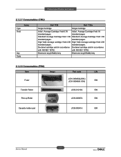
...standard pages. with ISO/IEC 19752. Electronic key(CRUM) Only Electronic key(CRUM) Only 2.1.2.8 Consumables (FRU) Item Image Fuser Transfer Roller Pick up Roller Part code Life JC91-00945A(220V) 50K JC91-00946A(110V) JC66-01218A 50K JC93-00087A 50K ...: Average cartridge Yield 2.5K standard pages. Product specification and feature 2.1.2.7 Consumables (CRU) Type Yield Items Key Code Dell 1133 Dell 1135n Single Cartridge Single Cartridge Initial : Average Cartridge Yield 0.7K Initial : Average Cartridge Yield 1K standard pages standard pages Standard: Average...
...standard pages. with ISO/IEC 19752. Electronic key(CRUM) Only Electronic key(CRUM) Only 2.1.2.8 Consumables (FRU) Item Image Fuser Transfer Roller Pick up Roller Part code Life JC91-00945A(220V) 50K JC91-00946A(110V) JC66-01218A 50K JC93-00087A 50K ...: Average cartridge Yield 2.5K standard pages. Product specification and feature 2.1.2.7 Consumables (CRU) Type Yield Items Key Code Dell 1133 Dell 1135n Single Cartridge Single Cartridge Initial : Average Cartridge Yield 0.7K Initial : Average Cartridge Yield 1K standard pages standard pages Standard: Average...

Service Manual
Page 24
... Cartridge 5 OPE 6 ADF 7 Platen 8 Feed roller Service Manual 9 Separation Pad 10 Pick up roller 11 Transfer roller 12 OPC 13 Cassette 14 Pressure roller 15 Fuser Exit roller 2-12
... Cartridge 5 OPE 6 ADF 7 Platen 8 Feed roller Service Manual 9 Separation Pad 10 Pick up roller 11 Transfer roller 12 OPC 13 Cassette 14 Pressure roller 15 Fuser Exit roller 2-12
Service Manual
Page 26
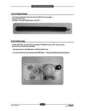
up, Feed, gear block all mounted as an assembly. • Driving Frequency: BLDCΦ55 Motor : 2200rpm(1650 Clock) • It is no PTL Ass'y. - There is a power delivery unit by gearing: BLDCΦ55 Motor - >Pickup/Feeder/Developer/Fuser/Duplex 2-14 Service Manual Product specification and feature 2.2.3.2 Transfer Roller - Life Span : Print over 50,000 sheets (in15~30ଇ) 2.2.3.3 Driver Assy - In Dell 1133/1135n, the driving device consisted of Φ55 BLDC motor, OPC, Pick- The transfer roller delivers the toner from the OPC drum to the paper. -
up, Feed, gear block all mounted as an assembly. • Driving Frequency: BLDCΦ55 Motor : 2200rpm(1650 Clock) • It is no PTL Ass'y. - There is a power delivery unit by gearing: BLDCΦ55 Motor - >Pickup/Feeder/Developer/Fuser/Duplex 2-14 Service Manual Product specification and feature 2.2.3.2 Transfer Roller - Life Span : Print over 50,000 sheets (in15~30ଇ) 2.2.3.3 Driver Assy - In Dell 1133/1135n, the driving device consisted of Φ55 BLDC motor, OPC, Pick- The transfer roller delivers the toner from the OPC drum to the paper. -

Service Manual
Page 27
... . The surface of a heat roller is coated with Teflon, so toner does not stick to prevent over- Product specification and feature 2.2.3.4 Fuser It is consists of a paper permanently. 5) Halogen Lamp - Thermostat Type : Non- Control Temperature : 170ଇ Gଇ 2) Thermistor It is overheated, a Thermostat cuts off the main...
... . The surface of a heat roller is coated with Teflon, so toner does not stick to prevent over- Product specification and feature 2.2.3.4 Fuser It is consists of a paper permanently. 5) Halogen Lamp - Thermostat Type : Non- Control Temperature : 170ଇ Gଇ 2) Thermistor It is overheated, a Thermostat cuts off the main...
Service Manual
Page 28
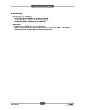
A fuser power is cut off main power. Maintain a temperature of fuser cover's surface under 80ଇ for overheating - 1st protection device: Hardware cuts off when overheated - 2nd protection device: Software cuts off when overheated - 3rd protection device: Thermostat cuts off when a front cover is opened - Safety device - Product specification and feature 6) Items for safety Protecting device for user, and attach a caution label at where customer can see easily when customer open a rear cover. 2-16 Service Manual
A fuser power is cut off main power. Maintain a temperature of fuser cover's surface under 80ଇ for overheating - 1st protection device: Hardware cuts off when overheated - 2nd protection device: Software cuts off when overheated - 3rd protection device: Thermostat cuts off when a front cover is opened - Safety device - Product specification and feature 6) Items for safety Protecting device for user, and attach a caution label at where customer can see easily when customer open a rear cover. 2-16 Service Manual

Service Manual
Page 31
... lamp, current control to the LSU and The CPU on Main PBA manages the circuits for the motors: paper feed, paper path, clutches, pre- CIS FUSER PLATEN MOTOR OPE ADF PPLLAATTEENN MMOOTTOORR IICC NETWORK NNeettwwoorrkk IICC USB UUSSBB 22..00 IICC EEEEPPRROOMM LINE EXT. FFAAXX CCOONNEEXXAANNTT LSU SPEAKER CRUM OUT BIN...
... lamp, current control to the LSU and The CPU on Main PBA manages the circuits for the motors: paper feed, paper path, clutches, pre- CIS FUSER PLATEN MOTOR OPE ADF PPLLAATTEENN MMOOTTOORR IICC NETWORK NNeettwwoorrkk IICC USB UUSSBB 22..00 IICC EEEEPPRROOMM LINE EXT. FFAAXX CCOONNEEXXAANNTT LSU SPEAKER CRUM OUT BIN...
Service Manual
Page 33
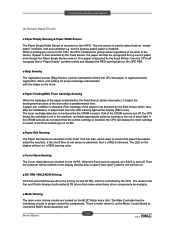
... by the Feed Sensor (photo interrupter), it will show invalid sign on a LED. ■ Paper Exit Sensing The Paper Exit Sensor is mounted on the Fuser Unit exit side, and is used to the CPU, the CPU initializes the pickup action regardless of the state of the paper is mounted on...
... by the Feed Sensor (photo interrupter), it will show invalid sign on a LED. ■ Paper Exit Sensing The Paper Exit Sensor is mounted on the Fuser Unit exit side, and is used to the CPU, the CPU initializes the pickup action regardless of the state of the paper is mounted on...

Service Manual
Page 34
... the high voltage of the machine. It is mounted on the side of THV/MHV/Supply/Dev and supplies it is possible to power the Fuser Unit. It is assembled by an independent module, so it to the developer portion f The HVPS portion takes the 24V and outputs the high voltage...
... the high voltage of the machine. It is mounted on the side of THV/MHV/Supply/Dev and supplies it is possible to power the Fuser Unit. It is assembled by an independent module, so it to the developer portion f The HVPS portion takes the 24V and outputs the high voltage...
Service Manual
Page 40
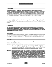
... The Heat Roller temperate (warmup) is measured by a qualified technician. • Low Heat Error After initial warmup had been achieved, if the Fuser Unit at the error state until the issue is resoled by converting the resistance of the thermistor to recovery mode and the engine informs the..., the paper is not in a ready status, the engine detects the error that can occur: • Open Heat Error During warmup, if the Fuser Unit does not reach its proper fusing temperature. The AD converter changes it to synchronize with no image on the Control Panel alerting the customer...
... The Heat Roller temperate (warmup) is measured by a qualified technician. • Low Heat Error After initial warmup had been achieved, if the Fuser Unit at the error state until the issue is resoled by converting the resistance of the thermistor to recovery mode and the engine informs the..., the paper is not in a ready status, the engine detects the error that can occur: • Open Heat Error During warmup, if the Fuser Unit does not reach its proper fusing temperature. The AD converter changes it to synchronize with no image on the Control Panel alerting the customer...

Service Manual
Page 55
Take off the user unit. 3-12 Service Manual Unplug the 2 connectors from SMPS board and Main board. 4. Dis ssem ly d e ssem ly 3.6 Fuser Unit 3.6.1 Whole Fuser Unit 1. emove 4 screws. 3. emove the rear and left cover. 2.
Take off the user unit. 3-12 Service Manual Unplug the 2 connectors from SMPS board and Main board. 4. Dis ssem ly d e ssem ly 3.6 Fuser Unit 3.6.1 Whole Fuser Unit 1. emove 4 screws. 3. emove the rear and left cover. 2.
Service Manual
Page 56
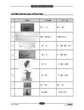
Dis ssem ly d e ssem ly 3.6.2 Main Service parts of Fuser Unit Photo P rt code P rt me 1 61 7- 1 2 SP I TS 66- 2364 TU TO E IT 3-13 Service Manual USE 67- 41 P USE L MP L 6 67- 414 P USE L MP 7 61 7- 116 SP I ES 2 4713- 1212 (22 ) L MP-H LO E 3 39- 19 H ESS USE OI T 4 39- 1 2 H ESS-
Dis ssem ly d e ssem ly 3.6.2 Main Service parts of Fuser Unit Photo P rt code P rt me 1 61 7- 1 2 SP I TS 66- 2364 TU TO E IT 3-13 Service Manual USE 67- 41 P USE L MP L 6 67- 414 P USE L MP 7 61 7- 116 SP I ES 2 4713- 1212 (22 ) L MP-H LO E 3 39- 19 H ESS USE OI T 4 39- 1 2 H ESS-

Service Manual
Page 58
Dis ssem ly d e ssem ly 3.6.3 Replacing the Main Service part of Fuser Unit 3.6.3.1 Spring-Es Separate it as take up the circle-area of Spring-Es from hook. 2 3-1 Service Manual
Dis ssem ly d e ssem ly 3.6.3 Replacing the Main Service part of Fuser Unit 3.6.3.1 Spring-Es Separate it as take up the circle-area of Spring-Es from hook. 2 3-1 Service Manual
Service Manual
Page 59
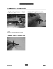
Disassemble ctuator-Exit from the actuator. Lift up the checking point and push to right side, and then disassemble. 3. Disassemble Spring-Ts from Holder- Dis ssem ly d e ssem ly 3.6.3.2 Actuator-Exit and Holder-Actuator 1. ctuator. 3-16 Service Manual aution : Do not touch the roller surface of fuser inside 2.
Disassemble ctuator-Exit from the actuator. Lift up the checking point and push to right side, and then disassemble. 3. Disassemble Spring-Ts from Holder- Dis ssem ly d e ssem ly 3.6.3.2 Actuator-Exit and Holder-Actuator 1. ctuator. 3-16 Service Manual aution : Do not touch the roller surface of fuser inside 2.
Service Manual
Page 60
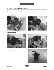
Dis ssem ly d e ssem ly 3.6.3.3 Cap-Fuser lamp R/Cap-Fuser Lamp L Press the hook end of latch away from the cover-fuser to which it is latched and separate it - Cap-Fuser Lamp R aution : Don t bend the stud 3-17 Service Manual Cap-Fuser Lamp L -
Dis ssem ly d e ssem ly 3.6.3.3 Cap-Fuser lamp R/Cap-Fuser Lamp L Press the hook end of latch away from the cover-fuser to which it is latched and separate it - Cap-Fuser Lamp R aution : Don t bend the stud 3-17 Service Manual Cap-Fuser Lamp L -
Service Manual
Page 62
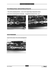
Pull out the connected part from the user. # 3.6.3.6 Thermostat Loose the two screws in the red circle and separate it. 3-19 Service Manual nd separate the harness from L ( efer to 3.4.3.4 Lamp-Halogen disassemble method). 2. Pull out the connected part from Thermostat. Dis ssem ly d e ssem ly 3.6.3.5 Harness-Fuser Joint and Harness-Fuser AC 1.
Pull out the connected part from the user. # 3.6.3.6 Thermostat Loose the two screws in the red circle and separate it. 3-19 Service Manual nd separate the harness from L ( efer to 3.4.3.4 Lamp-Halogen disassemble method). 2. Pull out the connected part from Thermostat. Dis ssem ly d e ssem ly 3.6.3.5 Harness-Fuser Joint and Harness-Fuser AC 1.
Service Manual
Page 63
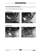
Dis ssem ly d e ssem ly 3.6.3.7 Lever Link Jam R/ Lever Link Jam LGG fter removing the E-ring and Washer-Plain , separate the lever. - Cap-Fuser Lamp L 3-2 Service Manual Cap-Fuser Lamp R -
Dis ssem ly d e ssem ly 3.6.3.7 Lever Link Jam R/ Lever Link Jam LGG fter removing the E-ring and Washer-Plain , separate the lever. - Cap-Fuser Lamp L 3-2 Service Manual Cap-Fuser Lamp R -


