Brochure
Page 3
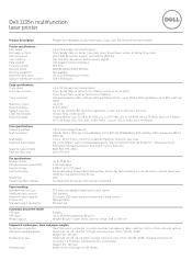
...Platen) Text and text/photo 600 x 600 dpi (ADF and Platen) Photo - enhanced: 4800 x 4800 dpi Colour: 16 bit; Dell 1135n multifunction laser printer Product description Reliable and affordable multifunction (print, copy, scan, fax) monochrome laser printer Printer specifications Print speed1 First page...% at 1% increments Scan specifications Scanning method Scan resolution Scan depth Scanning functionality Scale file types (Client) Effective scan area CIS (Contact Image Scanner) Optical: 1200 x 1200 dpi (Colour@Platen), 600 x 600 dpi (B/W@Platen) 600 x 600dpi (ADF); mono: one bit for lineart...
...Platen) Text and text/photo 600 x 600 dpi (ADF and Platen) Photo - enhanced: 4800 x 4800 dpi Colour: 16 bit; Dell 1135n multifunction laser printer Product description Reliable and affordable multifunction (print, copy, scan, fax) monochrome laser printer Printer specifications Print speed1 First page...% at 1% increments Scan specifications Scanning method Scan resolution Scan depth Scanning functionality Scale file types (Client) Effective scan area CIS (Contact Image Scanner) Optical: 1200 x 1200 dpi (Colour@Platen), 600 x 600 dpi (B/W@Platen) 600 x 600dpi (ADF); mono: one bit for lineart...

Service Manual
Page 5
Contents 3.2 Screws used in the printer 3-2 3.3 Cover 3-4 3.3.1 Front Cover 3-4 3.3.2 Rear Cover 3-4 3.3.3 Right/Left Cover 3-5 3.4 Scanner and ADF 3-6 3.4.1 ADF unit 3-6 3.4.2 ADF roller 3-7 3.4.3 OPE Unit 3-8 3.4.4 Platen unit 3-8 3.4.5 CIS unit 3-9 3.5 Middle Cover 3-10 3.6 Fuser Unit 3-12 3.6.1 Whole Fuser Unit 3-12 3.6.2 Main Service parts ...
Contents 3.2 Screws used in the printer 3-2 3.3 Cover 3-4 3.3.1 Front Cover 3-4 3.3.2 Rear Cover 3-4 3.3.3 Right/Left Cover 3-5 3.4 Scanner and ADF 3-6 3.4.1 ADF unit 3-6 3.4.2 ADF roller 3-7 3.4.3 OPE Unit 3-8 3.4.4 Platen unit 3-8 3.4.5 CIS unit 3-9 3.5 Middle Cover 3-10 3.6 Fuser Unit 3-12 3.6.1 Whole Fuser Unit 3-12 3.6.2 Main Service parts ...

Service Manual
Page 8
... be hazardous. Warning >> Never operate or service the printer with the protective cover removed from Laser/ Scanner assembly. Service Manual 1-1 This printer should always be serviced by a qualified service technician. (2) Use only Dell replacement parts There are dangerous. High voltages and lasers inside the printer. The laser system and printer...
... be hazardous. Warning >> Never operate or service the printer with the protective cover removed from Laser/ Scanner assembly. Service Manual 1-1 This printer should always be serviced by a qualified service technician. (2) Use only Dell replacement parts There are dangerous. High voltages and lasers inside the printer. The laser system and printer...
Service Manual
Page 22
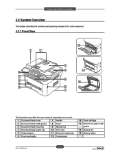
Product specification and feature 2.2 System Overview This chapter describes the functions and operating principal of the main component. 2.2.1 Front View This illustration may differ from your machine depending on its model. 1 Document feeder cover 7 Handle 2 Document feeder width guides 8 Tray 1 3 Document feeder input tray 9 Manual tray 4 Document feeder output tray 10 Front door 5 Output support 11 Document output tray 6 Front door handle 12 Control panel 13 Toner cartridge 14 Manual tray paper width guides 15 Scanner lid 16 Scanner glass 2-10 Service Manual
Product specification and feature 2.2 System Overview This chapter describes the functions and operating principal of the main component. 2.2.1 Front View This illustration may differ from your machine depending on its model. 1 Document feeder cover 7 Handle 2 Document feeder width guides 8 Tray 1 3 Document feeder input tray 9 Manual tray 4 Document feeder output tray 10 Front door 5 Output support 11 Document output tray 6 Front door handle 12 Control panel 13 Toner cartridge 14 Manual tray paper width guides 15 Scanner lid 16 Scanner glass 2-10 Service Manual

Service Manual
Page 29
... used to the controller. The controller detects the /HSYNC signal to the electrostatic latent image on paper. Product specification and feature 2.2.3.5 LSU (Laser Scanner Unit) It is the core part of the LBP which switches the video data received to the controller to adjust the vertical line of the...
... used to the controller. The controller detects the /HSYNC signal to the electrostatic latent image on paper. Product specification and feature 2.2.3.5 LSU (Laser Scanner Unit) It is the core part of the LBP which switches the video data received to the controller to adjust the vertical line of the...

Service Manual
Page 49
emove the D connector cover. 2. Lift the D unit up and release it. 3-6 Service Manual Dis ssem ly d e ssem ly 3.4 Scanner and ADF 3.4.1 ADF unit 1. Unplug the connector. 3.
emove the D connector cover. 2. Lift the D unit up and release it. 3-6 Service Manual Dis ssem ly d e ssem ly 3.4 Scanner and ADF 3.4.1 ADF unit 1. Unplug the connector. 3.

Service Manual
Page 53
Push up the scanner slightly. 4. emove the rear left right cover. 2. Dis ssem ly d e ssem ly 3.5 Middle Cover 1. Unplug 4 connectors including a lat cable. 3. Lift up both hooks from the bottom of middle cover. 3-1 Service Manual
Push up the scanner slightly. 4. emove the rear left right cover. 2. Dis ssem ly d e ssem ly 3.5 Middle Cover 1. Unplug 4 connectors including a lat cable. 3. Lift up both hooks from the bottom of middle cover. 3-1 Service Manual

Service Manual
Page 54
Dis ssem ly d e ssem ly . Lift up the scanner slightly angle 7 双 and remove the scanner. 7. Unplug 1 connector. 3-11 Service Manual elease the middle cover after removing 4 screws. 6.
Dis ssem ly d e ssem ly . Lift up the scanner slightly angle 7 双 and remove the scanner. 7. Unplug 1 connector. 3-11 Service Manual elease the middle cover after removing 4 screws. 6.

Service Manual
Page 78
Open the document feeder cover. 4. Gently remove the jammed original from the document feeder. 2. Reload the originals you see no paper in the document feeder. 3. Service Manual 4-5 Open the scanner lid. * If you removed, if any remaining originals from the document feeder. 5. Close the document feeder cover. Remove any , in this area, go to step 5. Alignment and Troubleshooting 4.1.3 JAM Removal 4.1.3.1 Clearing Original Document Jams When an original jams while passing through the document feeder, a warning message appears on the display screen. 1.
Open the document feeder cover. 4. Gently remove the jammed original from the document feeder. 2. Reload the originals you see no paper in the document feeder. 3. Service Manual 4-5 Open the scanner lid. * If you removed, if any remaining originals from the document feeder. 5. Close the document feeder cover. Remove any , in this area, go to step 5. Alignment and Troubleshooting 4.1.3 JAM Removal 4.1.3.1 Clearing Original Document Jams When an original jams while passing through the document feeder, a warning message appears on the display screen. 1.

Service Manual
Page 79
Close the scanner lid. Load the removed pages back into the document feeder. Note: Ensure the number of originals you place in the ADF does not exceed its tray capacity. 1 scanner lid Service Manual 4-6 Gently remove the original from the feed area by carefully pulling it to the right using both hands. 7. Alignment and Troubleshooting 6.
Close the scanner lid. Load the removed pages back into the document feeder. Note: Ensure the number of originals you place in the ADF does not exceed its tray capacity. 1 scanner lid Service Manual 4-6 Gently remove the original from the feed area by carefully pulling it to the right using both hands. 7. Alignment and Troubleshooting 6.
Service Manual
Page 135
... way to find out is to open the memo pad to check the function of IRQ 7 and 378 If the scanner needs to be connected to the printer, first the remove the scanner from the PC to see if the printer is properly working alone. If not working in the printing mode...
... way to find out is to open the memo pad to check the function of IRQ 7 and 378 If the scanner needs to be connected to the printer, first the remove the scanner from the PC to see if the printer is properly working alone. If not working in the printing mode...

Service Manual
Page 149
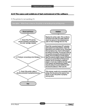
Replace main PBA. Check the Scanner Motor and any mechanical disturbance in Driver PBA. Service Manual 4-76 Check the Motor Driver in the CIS carriage part. 2. Alignment and Troubleshooting 3) Abnormal noise Description : There is noise when copy. 1. Check the right position of the Scanner Motor, and check the any mechanical disturbance.
Replace main PBA. Check the Scanner Motor and any mechanical disturbance in Driver PBA. Service Manual 4-76 Check the Motor Driver in the CIS carriage part. 2. Alignment and Troubleshooting 3) Abnormal noise Description : There is noise when copy. 1. Check the right position of the Scanner Motor, and check the any mechanical disturbance.

Service Manual
Page 150
Check the gap between original and scanner glass. Check shading profile. The gap above 0.5 mm can cause a blurred image. 3. Perform shading profile in the tech mode. 2. Check printing quality. Alignment and Troubleshooting 4) Defective Image Quality Description : The copied image is light or bad. 1. Service Manual 4-77 See "Print" troubleshooting.
Check the gap between original and scanner glass. Check shading profile. The gap above 0.5 mm can cause a blurred image. 3. Perform shading profile in the tech mode. 2. Check printing quality. Alignment and Troubleshooting 4) Defective Image Quality Description : The copied image is light or bad. 1. Service Manual 4-77 See "Print" troubleshooting.

Service Manual
Page 163
Re ere ce I or tio 6.2.2 Service Parts ACRONYM ELA HOU-SCANNER ASS'Y MEA UNIT-COVER PA EXIT ASS'Y PMO-TRAY EXTENTION MP NE MEC-CASSETTE ASS'Y (LETTER) COVER-M-FRONT MPR-NAME/PLATE UNIT-LSU 1 ELA-OPC ...
Re ere ce I or tio 6.2.2 Service Parts ACRONYM ELA HOU-SCANNER ASS'Y MEA UNIT-COVER PA EXIT ASS'Y PMO-TRAY EXTENTION MP NE MEC-CASSETTE ASS'Y (LETTER) COVER-M-FRONT MPR-NAME/PLATE UNIT-LSU 1 ELA-OPC ...

Service Manual
Page 164
Re ere ce I or tio ACRONYM SPECIAL SCREW (PANNEL MFP) A/S MATERAL-DUMMY UPPER ASS'Y PPR-REGISTRATION EDGE(F) MCT-GLASS SCANNER (LEGAL) CBF HARNESS-OPE COVER-SCAN LOWER (UMAX) ICT-INSERT SHAFTI IPR-BRK SCAN BD CBF SIGNAL-CCD FFC EXPLANATION MFP =Multi-Functional Peripheral A/S=After-...
Re ere ce I or tio ACRONYM SPECIAL SCREW (PANNEL MFP) A/S MATERAL-DUMMY UPPER ASS'Y PPR-REGISTRATION EDGE(F) MCT-GLASS SCANNER (LEGAL) CBF HARNESS-OPE COVER-SCAN LOWER (UMAX) ICT-INSERT SHAFTI IPR-BRK SCAN BD CBF SIGNAL-CCD FFC EXPLANATION MFP =Multi-Functional Peripheral A/S=After-...
User Guide
Page 6
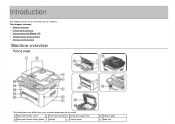
Introduction This chapter gives you an overview of your machine: This chapter includes: Machine overview Control panel overview Understanding the Status LED Introducing the useful buttons Turning on the machine Machine overview Front view This illustration may differ from your machine depending on its model. 1 Document feeder cover 6 Front door handle 11 Document output tray 2 Document feeder width guides 7 Handle 12 Control panel 16 Scanner glass 17 Scan unit
Introduction This chapter gives you an overview of your machine: This chapter includes: Machine overview Control panel overview Understanding the Status LED Introducing the useful buttons Turning on the machine Machine overview Front view This illustration may differ from your machine depending on its model. 1 Document feeder cover 6 Front door handle 11 Document output tray 2 Document feeder width guides 7 Handle 12 Control panel 16 Scanner glass 17 Scan unit

User Guide
Page 7
... feeder output tray 9 Manual tray 5 Output support 10 Front door [a] This button is used when you close button[a] 14 Manual tray paper width guides 15 Scanner lid This illustration may differ from your machine depending on its model. 1 Network port 5 Power receptacle 2 USB port 6 Rear door 3 Telephone line socket 7 Rear door...
... feeder output tray 9 Manual tray 5 Output support 10 Front door [a] This button is used when you close button[a] 14 Manual tray paper width guides 15 Scanner lid This illustration may differ from your machine depending on its model. 1 Network port 5 Power receptacle 2 USB port 6 Rear door 3 Telephone line socket 7 Rear door...
User Guide
Page 15
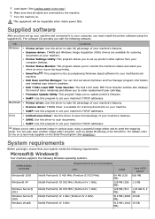
... on the SmarThru program (See Smarthru). Load paper (See Loading paper in various ways using the supplied CD. Dell 1135n Laser MFP Toner Reorder: The Dell 1133 Laser MFP Toner Reorder window also displays the level of your system meets the following requirements: Microsoft® ...Photoshop, from your machine's features. Macintosh Printer driver: Use this driver to take full advantage of your machine's TCP/IP addresses. Scanner driver: TWAIN driver is the accompanying Windows-based software for your machine. SetIP: Use this driver to send the image by email....
... on the SmarThru program (See Smarthru). Load paper (See Loading paper in various ways using the supplied CD. Dell 1135n Laser MFP Toner Reorder: The Dell 1133 Laser MFP Toner Reorder window also displays the level of your system meets the following requirements: Microsoft® ...Photoshop, from your machine's features. Macintosh Printer driver: Use this driver to take full advantage of your machine's TCP/IP addresses. Scanner driver: TWAIN driver is the accompanying Windows-based software for your machine. SetIP: Use this driver to send the image by email....
User Guide
Page 16
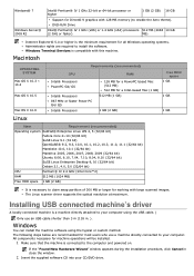
... in . ). The following steps below are required to the computer and powered on. Make sure that the machine is necessary to your computer. The Linux scanner driver supports the optical resolution at maximum. DVD-R/W Drive Intel® Pentium® IV 1 GHz (x86) or 1.4 GHz (x64) processors 512 MB (2048 10 GB...
... in . ). The following steps below are required to the computer and powered on. Make sure that the machine is necessary to your computer. The Linux scanner driver supports the optical resolution at maximum. DVD-R/W Drive Intel® Pentium® IV 1 GHz (x86) or 1.4 GHz (x64) processors 512 MB (2048 10 GB...
User Guide
Page 19
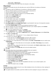
... that the machine is recommended for Macintosh. 1. Double-click the Installer OS X icon. 6. After the installation is set as you have installed scanner driver, click Restart. 13. and your computer and powered on . 2. Insert the supplied software CD into your computer and powered on . 2....the USB connection. 16. Double-click CD-ROM icon that the machine is done, click Quit. Select Uninstall and click Uninstall. 9. The Dell Installer window opens. Your machine appears on a Macintosh computer. For Mac OS X 10.5 ~ 10.6, click Default and find the USB ...
... that the machine is recommended for Macintosh. 1. Double-click the Installer OS X icon. 6. After the installation is set as you have installed scanner driver, click Restart. 13. and your computer and powered on . 2. Insert the supplied software CD into your computer and powered on . 2....the USB connection. 16. Double-click CD-ROM icon that the machine is done, click Quit. Select Uninstall and click Uninstall. 9. The Dell Installer window opens. Your machine appears on a Macintosh computer. For Mac OS X 10.5 ~ 10.6, click Default and find the USB ...


