User Manual
Page 2
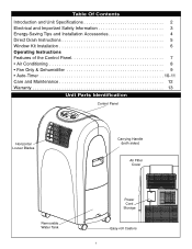
Table Of Contents Introduction and Unit Specifications 2 Electrical and Important Safety Information 3 Energy-Saving Tips and Installation Accessories 4 Direct Drain Instructions 5 Window Kit Installation 6 Operating Instructions Features of the Control Panel 7 • Air Conditioning 8 • Fan Only & Dehumidifier 9 • Auto-Timer 10-11 Care and Maintenance 12 Warranty 13 Unit Parts Identification Control Panel Horizontal Louver Blades Carrying Handle (both sides) Air Filter Cover Removable Water Tank Power Cord Storage Easy-roll Castors 1
Table Of Contents Introduction and Unit Specifications 2 Electrical and Important Safety Information 3 Energy-Saving Tips and Installation Accessories 4 Direct Drain Instructions 5 Window Kit Installation 6 Operating Instructions Features of the Control Panel 7 • Air Conditioning 8 • Fan Only & Dehumidifier 9 • Auto-Timer 10-11 Care and Maintenance 12 Warranty 13 Unit Parts Identification Control Panel Horizontal Louver Blades Carrying Handle (both sides) Air Filter Cover Removable Water Tank Power Cord Storage Easy-roll Castors 1
User Manual
Page 3
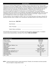
... moments and read the instructions thoroughly and familiarize yourself with all of the "Home Comfort" requirements for your home, cottage or office. Imagine the convenience of Portable Home Comfort at your home and set-up in steady improvement. Model Number: DPAC7008 Serial Number Date of...-processing appliance, designed to offer you the functions of Day Clock Auto - To contact a Customer Service Representative, call Danby TOLL FREE.1-800-26-DANBY Unit Specifications Model Number Cooling Capacity Noise Level Fan Speeds Airflow CFM High / Medium / Low Power Source Refrigerant Internal ...
... moments and read the instructions thoroughly and familiarize yourself with all of the "Home Comfort" requirements for your home, cottage or office. Imagine the convenience of Portable Home Comfort at your home and set-up in steady improvement. Model Number: DPAC7008 Serial Number Date of...-processing appliance, designed to offer you the functions of Day Clock Auto - To contact a Customer Service Representative, call Danby TOLL FREE.1-800-26-DANBY Unit Specifications Model Number Cooling Capacity Noise Level Fan Speeds Airflow CFM High / Medium / Low Power Source Refrigerant Internal ...
User Manual
Page 4
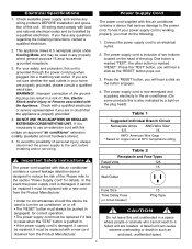
...safety and protection, this unit unattended in such an enclosed, unattended space. 3 Press the 'TEST' button, you must do the following instructions, contact a qualified electrician. 2. American Wire Gage * Based on the plug head). Table 2 Receptacle and Fuse Types Rated Volts 125 Amps... a click as the 'RESET' button pops out. 3. DO NOT USE PLUG ADAPTERS OR REGULAR EXTENSION CORDS WITHTHIS UNIT. Important Safety Instructions The power cord supplied with a qualified electrician or service representative if you are in (engaged) for details. This appliance draws 6.5 nameplate...
...safety and protection, this unit unattended in such an enclosed, unattended space. 3 Press the 'TEST' button, you must do the following instructions, contact a qualified electrician. 2. American Wire Gage * Based on the plug head). Table 2 Receptacle and Fuse Types Rated Volts 125 Amps... a click as the 'RESET' button pops out. 3. DO NOT USE PLUG ADAPTERS OR REGULAR EXTENSION CORDS WITHTHIS UNIT. Important Safety Instructions The power cord supplied with a qualified electrician or service representative if you are in (engaged) for details. This appliance draws 6.5 nameplate...
User Manual
Page 5
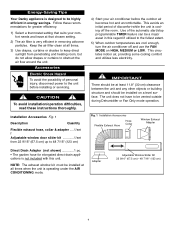
...utilizes less electricity. IMPORTANT There should be at all times when the unit is very efficient in this unit. Energy-Saving Tips Your Danby appliance is designed to be installed on HIGH, MEDIUM or LOW. Use of discomfort while the unit is not included with this regard... and heating room, but do not allow drapes or curtains to the unit before the outdoor air becomes hot and uncomfortable. Follow these instructions thoroughly. This avoids an initial period of the automatic start/stop programmable TIMER feature can be installed at that chosen setting. 2) The ...
...utilizes less electricity. IMPORTANT There should be at all times when the unit is very efficient in this unit. Energy-Saving Tips Your Danby appliance is designed to be installed on HIGH, MEDIUM or LOW. Use of discomfort while the unit is not included with this regard... and heating room, but do not allow drapes or curtains to the unit before the outdoor air becomes hot and uncomfortable. Follow these instructions thoroughly. This avoids an initial period of the automatic start/stop programmable TIMER feature can be installed at that chosen setting. 2) The ...
User Manual
Page 6
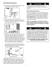
... prevents the unit from condensing water in Figure 2. Remove the internal water tank; Direct Drain Tube Please Note: Remember to reverse the above direct drain instructions when relocating the unit to another location. 1 Fig.2 2 2. gently lift then pull outward as shown in the event the internal water tank is accidentally displaced... of the water tank inside the cabinet. Locate the direct drain hose Figure 3 (a), and proceed to suit your continuous drain option requirements. b Fig.3 3. Direct Drain Instructions 1.
... prevents the unit from condensing water in Figure 2. Remove the internal water tank; Direct Drain Tube Please Note: Remember to reverse the above direct drain instructions when relocating the unit to another location. 1 Fig.2 2 2. gently lift then pull outward as shown in the event the internal water tank is accidentally displaced... of the water tank inside the cabinet. Locate the direct drain hose Figure 3 (a), and proceed to suit your continuous drain option requirements. b Fig.3 3. Direct Drain Instructions 1.
User Manual
Page 8
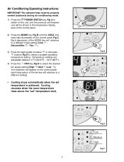
... are adjustable between 17°C (62.6°F) ~ 30°C (86°F ). 4) Press the FAN key Fig E to select a suitable operating temperature setting. Air Conditioning Operating Instructions: IMPORTANT: The exhaust hose must be shown in the temperature display area of the control panel. 2) Press the MODE key Fig B. Each depression of the...
... are adjustable between 17°C (62.6°F) ~ 30°C (86°F ). 4) Press the FAN key Fig E to select a suitable operating temperature setting. Air Conditioning Operating Instructions: IMPORTANT: The exhaust hose must be shown in the temperature display area of the control panel. 2) Press the MODE key Fig B. Each depression of the...
User Manual
Page 9
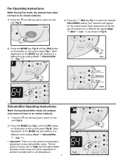
...H until the DRY indicator illuminates on the control panel Fig M. Fig H MODE MODE CF 5 MODE Fig J Low Medium High Fig K MODE Dehumidifier Operating Instructions: Note: During dehumidifier mode, the exhaust hose does not have to be vented outdoors. 1) Press the (on/off ) key pad to switch on the unit.... Each depression of ambient humidity level or set temperature. 9 Fig L MODE CF Fig M MODE Fan Operating Instructions: Note: During Fan mode, the exhaust hose does not have to be vented outdoors. 1) Press the (on/off ) key pad to switch on the...
...H until the DRY indicator illuminates on the control panel Fig M. Fig H MODE MODE CF 5 MODE Fig J Low Medium High Fig K MODE Dehumidifier Operating Instructions: Note: During dehumidifier mode, the exhaust hose does not have to be vented outdoors. 1) Press the (on/off ) key pad to switch on the unit.... Each depression of ambient humidity level or set temperature. 9 Fig L MODE CF Fig M MODE Fan Operating Instructions: Note: During Fan mode, the exhaust hose does not have to be vented outdoors. 1) Press the (on/off ) key pad to switch on the...
User Manual
Page 10
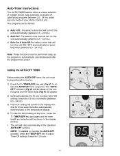
... a time that will be (operational) turned on. 1) Press the TIMER-OFF key pad (Fig N) to initiate the AUTO-OFF time sequence. MOD 10 Auto-Timer Instructions: The AUTO-TIMER feature offers a unique selection of your Home Comfort unit. Setting the AUTO-OFF TIMER Before setting the AUTO-OFF timer, the unit...
... a time that will be (operational) turned on. 1) Press the TIMER-OFF key pad (Fig N) to initiate the AUTO-OFF time sequence. MOD 10 Auto-Timer Instructions: The AUTO-TIMER feature offers a unique selection of your Home Comfort unit. Setting the AUTO-OFF TIMER Before setting the AUTO-OFF timer, the unit...
User Manual
Page 12
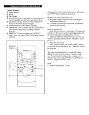
... cover seperates completely from the unit. 2. The remote operates within a range of 8 meters (26 ft.) from the receiver located inside the battery chamber (+/-). 3. Remote Control Instructions Control Buttons 1) Power Switch 2) Mode 3) Fan Speed 4) Used to increase or decrease the temperature to select a suitable operating temperature setting. 5) Lock: Prevents the remote control...
... cover seperates completely from the unit. 2. The remote operates within a range of 8 meters (26 ft.) from the receiver located inside the battery chamber (+/-). 3. Remote Control Instructions Control Buttons 1) Power Switch 2) Mode 3) Fan Speed 4) Used to increase or decrease the temperature to select a suitable operating temperature setting. 5) Lock: Prevents the remote control...