Brochure
Page 1
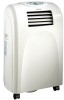
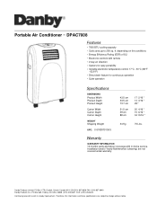
... not covered under warranty. Danby Products Limited. Portable Air Conditioner ~ DPAC7008 Features 7000 BTU cooling capacity Cools area up to change without notice. Warranty WARRANTY INFORMATION 12 months parts and labour coverage with remote 2 way air direction Castors for easy portability Variable electronic temperature control 17°C - 30°C (86°F - 62.6°F) Direct drain feature for continuous operation Quiet operation Specifications DIMENSIONS Product Width Product Depth Product Height Carton Width Carton Depth Carton Height WEIGHT Shipping Weight UPC: 0 6763870136...
... not covered under warranty. Danby Products Limited. Portable Air Conditioner ~ DPAC7008 Features 7000 BTU cooling capacity Cools area up to change without notice. Warranty WARRANTY INFORMATION 12 months parts and labour coverage with remote 2 way air direction Castors for easy portability Variable electronic temperature control 17°C - 30°C (86°F - 62.6°F) Direct drain feature for continuous operation Quiet operation Specifications DIMENSIONS Product Width Product Depth Product Height Carton Width Carton Depth Carton Height WEIGHT Shipping Weight UPC: 0 6763870136...
User Manual
Page 2
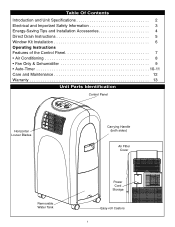
Table Of Contents Introduction and Unit Specifications 2 Electrical and Important Safety Information 3 Energy-Saving Tips and Installation Accessories 4 Direct Drain Instructions 5 Window Kit Installation 6 Operating Instructions Features of the Control Panel 7 • Air Conditioning 8 • Fan Only & Dehumidifier 9 • Auto-Timer 10-11 Care and Maintenance 12 Warranty 13 Unit Parts Identification Control Panel Horizontal Louver Blades Carrying Handle (both sides) Air Filter Cover Removable Water Tank Power Cord Storage Easy-roll Castors 1
Table Of Contents Introduction and Unit Specifications 2 Electrical and Important Safety Information 3 Energy-Saving Tips and Installation Accessories 4 Direct Drain Instructions 5 Window Kit Installation 6 Operating Instructions Features of the Control Panel 7 • Air Conditioning 8 • Fan Only & Dehumidifier 9 • Auto-Timer 10-11 Care and Maintenance 12 Warranty 13 Unit Parts Identification Control Panel Horizontal Louver Blades Carrying Handle (both sides) Air Filter Cover Removable Water Tank Power Cord Storage Easy-roll Castors 1
User Manual
Page 3
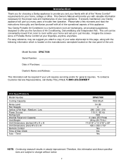
... functions of Portable Home Comfort at your home and set-up in steady improvement. To contact a Customer Service Representative, call Danby TOLL FREE.1-800-26-DANBY Unit Specifications Model Number Cooling Capacity Noise Level Fan Speeds Airflow CFM High / Medium / Low Power Source Refrigerant Internal Reservoir Capacity Unit Weight Unit Dimensions (inches) W x D x H Unit Dimensions (mm) W x D x H Remote Control Time of trouble free operation. This Owner's Manual will provide you many years of Day Clock Auto - If properly maintained, your Danby appliance will...
... functions of Portable Home Comfort at your home and set-up in steady improvement. To contact a Customer Service Representative, call Danby TOLL FREE.1-800-26-DANBY Unit Specifications Model Number Cooling Capacity Noise Level Fan Speeds Airflow CFM High / Medium / Low Power Source Refrigerant Internal Reservoir Capacity Unit Weight Unit Dimensions (inches) W x D x H Unit Dimensions (mm) W x D x H Remote Control Time of trouble free operation. This Owner's Manual will provide you many years of Day Clock Auto - If properly maintained, your Danby appliance will...
User Manual
Page 4
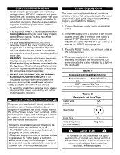
... it fails to the power cord. All wiring must do the following instructions, contact a qualified electrician. 2. Table 2 Receptacle and Fuse Types Rated Volts 125 Amps 15 Wall Outlet Fuse Size Time Delay Fuse (or circuit breaker) 15 Plug Type CAUTION Do not leave this unitu,se an approved "air conditioner" extension cordonly (available at 60°C temperature rating. American Wire Gage * Based on or off. • The 'RESET' button must always be pushed...
... it fails to the power cord. All wiring must do the following instructions, contact a qualified electrician. 2. Table 2 Receptacle and Fuse Types Rated Volts 125 Amps 15 Wall Outlet Fuse Size Time Delay Fuse (or circuit breaker) 15 Plug Type CAUTION Do not leave this unitu,se an approved "air conditioner" extension cordonly (available at 60°C temperature rating. American Wire Gage * Based on or off. • The 'RESET' button must always be pushed...
User Manual
Page 5
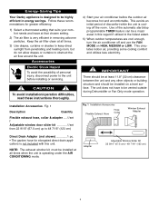
.... Fig. 1 Installation Accessories Flexible Exhaust Hose Hose Collar Window Exhaust Adapter Direct Drain Adapter (not shown 1 pc. • The garden hose for greater efficiency: 1) Select a thermostat setting that suits your comfort needs and leave at all times. 3) Use drapes, curtains or shades to keep direct sunlight from 22 9/16" (67.5 cm) up to 48 7/16" (123 cm) 4) Start your air conditioner before installing or servicing. Follow these instructions thoroughly. Accessories Electric Shock Hazard...
.... Fig. 1 Installation Accessories Flexible Exhaust Hose Hose Collar Window Exhaust Adapter Direct Drain Adapter (not shown 1 pc. • The garden hose for greater efficiency: 1) Select a thermostat setting that suits your comfort needs and leave at all times. 3) Use drapes, curtains or shades to keep direct sunlight from 22 9/16" (67.5 cm) up to 48 7/16" (123 cm) 4) Start your air conditioner before installing or servicing. Follow these instructions thoroughly. Accessories Electric Shock Hazard...
User Manual
Page 6
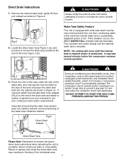
.... Direct Drain Instructions 1. Remove the internal water tank; Locate the direct drain hose Figure 3 (a), and proceed to replace and recap the direct drain hose may take 3-5 minutes before the "protection circuit" self-deactivates. Important: Ensure that the drain hose section does not interfere with a fail-safe switch mechanism which prevents the unit from condensing water in Figure 2. If required, attach the included drain hose adapter (Fig 4) to a location where continuous drain is automatically activated. The compressor...
.... Direct Drain Instructions 1. Remove the internal water tank; Locate the direct drain hose Figure 3 (a), and proceed to replace and recap the direct drain hose may take 3-5 minutes before the "protection circuit" self-deactivates. Important: Ensure that the drain hose section does not interfere with a fail-safe switch mechanism which prevents the unit from condensing water in Figure 2. If required, attach the included drain hose adapter (Fig 4) to a location where continuous drain is automatically activated. The compressor...
User Manual
Page 7
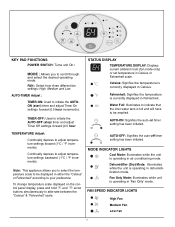
... (start) timer and adjust Timer On settings forward (0.5 hour increments). Dehumidifier (Dry) Mode: Illuminates while the unit is operating in dehumidification mode. High Medium and Low. TEMPERATURE Adjust: Continually depress to adjust temperature settings forward (1°C / °F increments). AUTO-ON: Signifies the auto-on the control panel display, press and hold and arrow buttons simultaneously to alternate between the "Celsius" & "Fahrenheit" scale. CF MODE KEY PAD FUNCTIONS POWER SWITCH: Turns unit On / MODE : Allows...
... (start) timer and adjust Timer On settings forward (0.5 hour increments). Dehumidifier (Dry) Mode: Illuminates while the unit is operating in dehumidification mode. High Medium and Low. TEMPERATURE Adjust: Continually depress to adjust temperature settings forward (1°C / °F increments). AUTO-ON: Signifies the auto-on the control panel display, press and hold and arrow buttons simultaneously to alternate between the "Celsius" & "Fahrenheit" scale. CF MODE KEY PAD FUNCTIONS POWER SWITCH: Turns unit On / MODE : Allows...
User Manual
Page 8
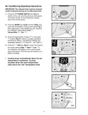
... will advance to a different mode setting (Cool Dehumidifier - Your selection will appear on the control panel (each depression of the MODE key will advance to a different setting). • Cooling stops automatically when the set temperature is achieved. until the COOL indicator light illuminates on the control panel Fig C. Air Conditioning Operating Instructions: IMPORTANT: The exhaust hose must be shown in the temperature display area of the control panel. 2) Press the MODE key Fig B. Fan ). 3) Press the appropriate...
... will advance to a different mode setting (Cool Dehumidifier - Your selection will appear on the control panel (each depression of the MODE key will advance to a different setting). • Cooling stops automatically when the set temperature is achieved. until the COOL indicator light illuminates on the control panel Fig C. Air Conditioning Operating Instructions: IMPORTANT: The exhaust hose must be shown in the temperature display area of the control panel. 2) Press the MODE key Fig B. Fan ). 3) Press the appropriate...
User Manual
Page 9
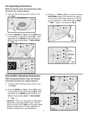
... the DRY indicator illuminates on the control panel Fig M. Each depression of the MODE key will advance to a different mode setting (Cool -Dehumidifier - Each depression of the MODE key will advance to a different mode setting (Cool -Dehumidifier - Fig H MODE MODE CF 5 MODE Fig J Low Medium High Fig K MODE Dehumidifier Operating Instructions: Note: During dehumidifier mode, the exhaust hose does not have to be vented outdoors. 1) Press the (on/off ) key pad to switch...
... the DRY indicator illuminates on the control panel Fig M. Each depression of the MODE key will advance to a different mode setting (Cool -Dehumidifier - Each depression of the MODE key will advance to a different mode setting (Cool -Dehumidifier - Fig H MODE MODE CF 5 MODE Fig J Low Medium High Fig K MODE Dehumidifier Operating Instructions: Note: During dehumidifier mode, the exhaust hose does not have to be vented outdoors. 1) Press the (on/off ) key pad to switch...
User Manual
Page 10
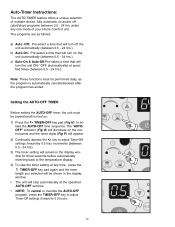
... timer, the unit must be shown in the display window for three seconds before automatically reverting back to the temperature display. 4) To view the timer setting at any one mode of your Home Comfort unit. MOD 10 press the TIMER-OFF key pad again and the timer length you selected will stop ) programs between 0.5 - 24 hrs.). Note: These functions must be (operational) turned on the control panel...
... timer, the unit must be shown in the display window for three seconds before automatically reverting back to the temperature display. 4) To view the timer setting at any one mode of your Home Comfort unit. MOD 10 press the TIMER-OFF key pad again and the timer length you selected will stop ) programs between 0.5 - 24 hrs.). Note: These functions must be (operational) turned on the control panel...
User Manual
Page 11
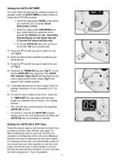
When setting the auto-on and auto off timer, the operation (running) time of operation. 11 The "AUTOON" indicator light (Fig U) will illuminate on the control panel and the timer digits (Fig V) will appear in the display window. • The unit will be turned "off" (non-operational). 1) Press the (on and auto-off . Fig S 4) Press the TIMER-ON key pad (Fig T) to adjust Timer On settings forward by 0.5 hour increments...
When setting the auto-on and auto off timer, the operation (running) time of operation. 11 The "AUTOON" indicator light (Fig U) will illuminate on the control panel and the timer digits (Fig V) will appear in the display window. • The unit will be turned "off" (non-operational). 1) Press the (on and auto-off . Fig S 4) Press the TIMER-ON key pad (Fig T) to adjust Timer On settings forward by 0.5 hour increments...
User Manual
Page 12
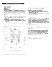
... the main unit. Remote Control Instructions Control Buttons 1) Power Switch 2) Mode 3) Fan Speed 4) Used to increase or decrease the temperature to select a suitable operating temperature setting. 5) Lock: Prevents the remote control settings from being inadvertently being changed. 6) Restore remote control default settings. 7) TIMER-ON: Used to initiate the AUTO-ON (start) timer and adjust Timer On settings forward (0.5/1h) 8) TIMER-OFF: Used to initiate the AUTO-OFF (stop) timer and adjust Timer Off settings forward (0.5/1h) Electronic Display TEMP.(°C) 1 2 4 3 7 To operate the...
... the main unit. Remote Control Instructions Control Buttons 1) Power Switch 2) Mode 3) Fan Speed 4) Used to increase or decrease the temperature to select a suitable operating temperature setting. 5) Lock: Prevents the remote control settings from being inadvertently being changed. 6) Restore remote control default settings. 7) TIMER-ON: Used to initiate the AUTO-ON (start) timer and adjust Timer On settings forward (0.5/1h) 8) TIMER-OFF: Used to initiate the AUTO-OFF (stop) timer and adjust Timer Off settings forward (0.5/1h) Electronic Display TEMP.(°C) 1 2 4 3 7 To operate the...
User Manual
Page 13
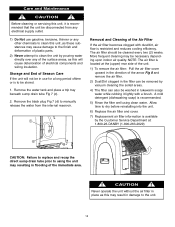
... drain tube Fig 7 (c). 2. NOTE: The air filter is restricted and reduces cooling efficiency. Care and Maintenance CAUTION Before cleaning or servicing this unit, it lightly with dust/dirt, air flow is located at : 1-800-26-DANBY (1-800-263-2629) d Fig.7 CAUTION: Failure to replace and recap the direct sump drain tube prior to using clean water. The air filter should be necessary depending upon indoor air quality. Remove the black plug Fig 7 (d) to the unit...
... drain tube Fig 7 (c). 2. NOTE: The air filter is restricted and reduces cooling efficiency. Care and Maintenance CAUTION Before cleaning or servicing this unit, it lightly with dust/dirt, air flow is located at : 1-800-26-DANBY (1-800-263-2629) d Fig.7 CAUTION: Failure to replace and recap the direct sump drain tube prior to using clean water. The air filter should be necessary depending upon indoor air quality. Remove the black plug Fig 7 (d) to the unit...
User Manual
Page 14
... AIR CONDITIONER WARRANTY This quality product is warranted to be free from purchase date, with no extensions provided. TERMS OF WARRANTY Plastic parts, are warranted for thirty (30) days only from manufacturer's defects in material and workmanship, provided that the unit is used for commercial application, all other than an authorized service depot, or the unit is used under any of the following: 1) Power...
... AIR CONDITIONER WARRANTY This quality product is warranted to be free from purchase date, with no extensions provided. TERMS OF WARRANTY Plastic parts, are warranted for thirty (30) days only from manufacturer's defects in material and workmanship, provided that the unit is used for commercial application, all other than an authorized service depot, or the unit is used under any of the following: 1) Power...


