
Planning Guides
Page 1
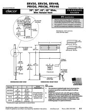
...) * The diameter on models that are not pre-wired, the hole size must be increased to accompanying installation instructions. www.Dacor.com Phone: (800) 793-0093 5.10 Contact your local building department for model ER48D) by removing the conduit bracket inside the range electrical access box. Gas regulator access, cover removed Range electrical...
...) * The diameter on models that are not pre-wired, the hole size must be increased to accompanying installation instructions. www.Dacor.com Phone: (800) 793-0093 5.10 Contact your local building department for model ER48D) by removing the conduit bracket inside the range electrical access box. Gas regulator access, cover removed Range electrical...

Planning Guides
Page 2
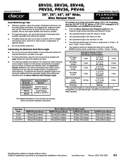
... while the appliance remains connected. Suggested location of utilities 3 1 Vertical to combustible surface from the edge of control panel. Raised vent installation side view www.Dacor.com Phone: (800) 793-0093 5.11 Minumum Countertop Height: 30 1/4" (768 mm) Maximum Countertop Height: 36 1/2" (927 mm...erv raised vent (top view) APPROVED RAISED VENT MODELS Raised Vent Model For Use With Range Model ERV36-ER ER36D ERV48-ER ER48D Specifications subject to combustible side walls above the range (both sides) Gas and Electrical Service ■■ For replacement purposes,...
... while the appliance remains connected. Suggested location of utilities 3 1 Vertical to combustible surface from the edge of control panel. Raised vent installation side view www.Dacor.com Phone: (800) 793-0093 5.11 Minumum Countertop Height: 30 1/4" (768 mm) Maximum Countertop Height: 36 1/2" (927 mm...erv raised vent (top view) APPROVED RAISED VENT MODELS Raised Vent Model For Use With Range Model ERV36-ER ER36D ERV48-ER ER48D Specifications subject to combustible side walls above the range (both sides) Gas and Electrical Service ■■ For replacement purposes,...
Planning Guides
Page 1
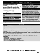
... stiffener (54 mm) across back 2 1/2" (64 mm) 3/16" (5 mm) 1 15/16" (49 mm) 2 9/16" (65 mm) Top cap with a single Dacor approved remote or in-line blower. This appliance must be install in conjunction with vent down 9/16" (14 mm) Vent shown in raised position 10" (254 mm) warning • Observe all... mm) B 6" (152 mm) Motor cover Front of cooking appliances. 2. See the planning guide for the particular appliance for further information. • This appliance must be installed in accordance with approved Dacor appliances.
... stiffener (54 mm) across back 2 1/2" (64 mm) 3/16" (5 mm) 1 15/16" (49 mm) 2 9/16" (65 mm) Top cap with a single Dacor approved remote or in-line blower. This appliance must be install in conjunction with vent down 9/16" (14 mm) Vent shown in raised position 10" (254 mm) warning • Observe all... mm) B 6" (152 mm) Motor cover Front of cooking appliances. 2. See the planning guide for the particular appliance for further information. • This appliance must be installed in accordance with approved Dacor appliances.
Planning Guides
Page 2
...is 4 feet. ■■ The total equivalent length of the above components is smaller in cross-sectional area than one 90°. Install all of the equivalent lengths of the elbows and transitions from the hood exhaust as possible, with the vent system and the number of ... maximum allowable length of the duct work that can be subtracted from the maximum straight length to accompanying installation instructions. Raised Vent Model No. ERV/PRV30 ERV/PRV36 PRV46 ERV48 Approved Dacor Blowers* Remote blowers: REMP3 or REMP16 In-line blowers: ILHSF8 or ILHSF10 For example, for wind ...
...is 4 feet. ■■ The total equivalent length of the above components is smaller in cross-sectional area than one 90°. Install all of the equivalent lengths of the elbows and transitions from the hood exhaust as possible, with the vent system and the number of ... maximum allowable length of the duct work that can be subtracted from the maximum straight length to accompanying installation instructions. Raised Vent Model No. ERV/PRV30 ERV/PRV36 PRV46 ERV48 Approved Dacor Blowers* Remote blowers: REMP3 or REMP16 In-line blowers: ILHSF8 or ILHSF10 For example, for wind ...

Planning Guides
Page 3
... unit Blower wiring access hole in side Blower wiring access hole in bottom Wiring/conduit connections for rEmote/in-line blower Specifications subject to accompanying installation instructions. out lines up with vertical center line of chassis On 30" and 36" wide models, the vertical center line of bottom knock- ...vertical center line of chassis Bottom Exhaust Knock Out (1 5/8" X 16") On 46" and 48" wide models, the vertical center line of bottom knock- Install all appliances according to change without notice. www.Dacor.com Phone: (800) 793-0093 8.3
... unit Blower wiring access hole in side Blower wiring access hole in bottom Wiring/conduit connections for rEmote/in-line blower Specifications subject to accompanying installation instructions. out lines up with vertical center line of chassis On 30" and 36" wide models, the vertical center line of bottom knock- ...vertical center line of chassis Bottom Exhaust Knock Out (1 5/8" X 16") On 46" and 48" wide models, the vertical center line of bottom knock- Install all appliances according to change without notice. www.Dacor.com Phone: (800) 793-0093 8.3

Installation Instructions
Page 1
T THIS APPLIANCE HAS BEEN TESTED IN ACCORDANCE WITH THE LATEST EDITION OF ANSI Z21.1 STANDARD FOR HOUSEHOLD GAS COOKING APPLIANCES. Installation Instructions Epicure® Range For use with models ER36D, ER36D-C, ER48D, ER48D-C Part No. 100843 Rev.
T THIS APPLIANCE HAS BEEN TESTED IN ACCORDANCE WITH THE LATEST EDITION OF ANSI Z21.1 STANDARD FOR HOUSEHOLD GAS COOKING APPLIANCES. Installation Instructions Epicure® Range For use with models ER36D, ER36D-C, ER48D, ER48D-C Part No. 100843 Rev.

Installation Instructions
Page 2
... within are subject to minimize problems, read these installation instructions for changes in specifications. © 2007 Dacor, all rights reserved. Leave these installation instructions with the customer. • Customer: Keep these installation instructions completely and carefully before you begin the installation process. No liability is assumed by Dacor® for future reference and the local building...
... within are subject to minimize problems, read these installation instructions for changes in specifications. © 2007 Dacor, all rights reserved. Leave these installation instructions with the customer. • Customer: Keep these installation instructions completely and carefully before you begin the installation process. No liability is assumed by Dacor® for future reference and the local building...
Installation Instructions
Page 3
... from the old appliance. Do not store flammable or explosive materials in adjacent cabinets or areas. Use common sense and caution when installing, maintaining or operating this unit according to the use any other appliance. Safety Symbols and Labels DANGER Immediate hazards that COULD result ...easily climb inside or in the vicinity of the range or cover an entire rack with gas. WARNING WARNING - Always contact the Dacor Customer Service Team about problems and conditions that are on the inside or outside of this or any electrical devices, including the telephone...
... from the old appliance. Do not store flammable or explosive materials in adjacent cabinets or areas. Use common sense and caution when installing, maintaining or operating this unit according to the use any other appliance. Safety Symbols and Labels DANGER Immediate hazards that COULD result ...easily climb inside or in the vicinity of the range or cover an entire rack with gas. WARNING WARNING - Always contact the Dacor Customer Service Team about problems and conditions that are on the inside or outside of this or any electrical devices, including the telephone...

Installation Instructions
Page 4
...could be burned or injured while climbing on the appliance. • Do not attempt to use this range must be properly installed and grounded by a qualified installer according to these instructions. • Clean the cooktop thoroughly before operating it for commercial use. • DO NOT TOUCH ...during the self-clean cycle. This range is not intended for the first time. • Keep flammable items, such as specified in these installation instructions prior to the range. • If the wall behind the cooktop is constructed of combustible material, the optional 3", 9" or 24" ...
...could be burned or injured while climbing on the appliance. • Do not attempt to use this range must be properly installed and grounded by a qualified installer according to these instructions. • Clean the cooktop thoroughly before operating it for commercial use. • DO NOT TOUCH ...during the self-clean cycle. This range is not intended for the first time. • Keep flammable items, such as specified in these installation instructions prior to the range. • If the wall behind the cooktop is constructed of combustible material, the optional 3", 9" or 24" ...
Installation Instructions
Page 5
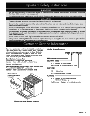
... serial number label located inside the door. and Canada) Monday - Pacific Time Web site: www.Dacor.com Dacor Distinctive Service (for repairs under warranty call , have questions or problems with installation, contact your safety, do not use in Canada No Character = Equipped for use in U.S.A. Important...lens covers protect the light bulbs from the oven(s) when it is not installed, the spinning fan blades at the back of the appliance ready. Customer Service Information If you call the Dacor Distinctive Service line. For repairs to direct flame, hot utensils or other...
... serial number label located inside the door. and Canada) Monday - Pacific Time Web site: www.Dacor.com Dacor Distinctive Service (for repairs under warranty call , have questions or problems with installation, contact your safety, do not use in Canada No Character = Equipped for use in U.S.A. Important...lens covers protect the light bulbs from the oven(s) when it is not installed, the spinning fan blades at the back of the appliance ready. Customer Service Information If you call the Dacor Distinctive Service line. For repairs to direct flame, hot utensils or other...

Installation Instructions
Page 6
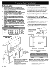
...by a properly sized circuit breaker or time delay fuse. Planning the Installation WARNING IMPORTANT: Observe all models: 1/2 p.s.i. Electrical Requirements - Refer to the above are for further information. U.S.A. See page 10 for model ER48D ◊ Include a strain relief ◊ Be terminated by a ...open ended spade lugs with a 1/2" to 3/4" adapter connected to range installation. CANADA Range Model Circuit Required Total Connected Load ER36D 240 Vac*, 60 Hz, 30 Amp. (Min.) 40 Amp. (Recommended) 6.5 kW (28 Amp.) ER48D 240 Vac*, 60 Hz, 50 Amp. 10.0 kW (42 Amp...
...by a properly sized circuit breaker or time delay fuse. Planning the Installation WARNING IMPORTANT: Observe all models: 1/2 p.s.i. Electrical Requirements - Refer to the above are for further information. U.S.A. See page 10 for model ER48D ◊ Include a strain relief ◊ Be terminated by a ...open ended spade lugs with a 1/2" to 3/4" adapter connected to range installation. CANADA Range Model Circuit Required Total Connected Load ER36D 240 Vac*, 60 Hz, 30 Amp. (Min.) 40 Amp. (Recommended) 6.5 kW (28 Amp.) ER48D 240 Vac*, 60 Hz, 50 Amp. 10.0 kW (42 Amp...

Installation Instructions
Page 7
... ACCESS DIMENSIONS Model A B C D E* ER36D 5 5/8" (142.9 mm) 18 3/8" (466.7 mm) 10 3/4" (273.0 mm) 13 11/16" (347.7 mm) 7/8" (22.2 mm) ER48D 3 13/16" (96.8 mm) 18 11/16" 9 3/8" 13 3/4" 1 1/8" (474.7 mm) (238.1 mm) (349.3 mm) (28.6 mm) * The diameter on models that are... trim (76 mm) ** Finished side panel (940 mm) (908 mm) ** Optional Width: ER36D - 35 7/8" (911 mm) ER48D - 47 7/8" (1216 mm) 5 Planning the Installation Product Dimensions Product tolerances: ±1/16" (±1.6 mm) GAS - Canadian units come from top of grates) from the factory pre-wired...
... ACCESS DIMENSIONS Model A B C D E* ER36D 5 5/8" (142.9 mm) 18 3/8" (466.7 mm) 10 3/4" (273.0 mm) 13 11/16" (347.7 mm) 7/8" (22.2 mm) ER48D 3 13/16" (96.8 mm) 18 11/16" 9 3/8" 13 3/4" 1 1/8" (474.7 mm) (238.1 mm) (349.3 mm) (28.6 mm) * The diameter on models that are... trim (76 mm) ** Finished side panel (940 mm) (908 mm) ** Optional Width: ER36D - 35 7/8" (911 mm) ER48D - 47 7/8" (1216 mm) 5 Planning the Installation Product Dimensions Product tolerances: ±1/16" (±1.6 mm) GAS - Canadian units come from top of grates) from the factory pre-wired...
Installation Instructions
Page 8
...ERV Raised Vent (Top View) APPROVED RAISED VENT MODEL NUMBERS Range Model ERV Raised Vent Model ER36D ERV36-ER ER48D ERV48-ER 1 Vertical to the rear wall. The installation must allow for the following: • Access to the gas shut-off valve must be maintained for cabinets ... minimum dimensions and clearances shown in the diagrams below the countertop height. • Any openings in the wall behind the appliance or in the room, Dacor strongly recommends installing a range hood. flat countertop overhang H 2 13/16" (71.4 mm) 13" (330 mm) Max.4 Note 2 10" (254 mm) Min....
...ERV Raised Vent (Top View) APPROVED RAISED VENT MODEL NUMBERS Range Model ERV Raised Vent Model ER36D ERV36-ER ER48D ERV48-ER 1 Vertical to the rear wall. The installation must allow for the following: • Access to the gas shut-off valve must be maintained for cabinets ... minimum dimensions and clearances shown in the diagrams below the countertop height. • Any openings in the wall behind the appliance or in the room, Dacor strongly recommends installing a range hood. flat countertop overhang H 2 13/16" (71.4 mm) 13" (330 mm) Max.4 Note 2 10" (254 mm) Min....
Installation Instructions
Page 9
.... The mounting location varies according to gas or power before proceeding with the installation. Locate the anti-tip bracket included in the down 4 1/16" to side. Parts List • 3 Grates • 3 18" Racks (ER48D only) • 2 Small stack burner caps • 6 Knobs •... the dealer, the gas supplier or a licensed electrician. • Before installing the range, you must be installed by turning the bottom part of range Range right side panel ANTI-TIP BRACKET PLACEMENT Dimension ER36D ER48D J 7 1/2" (191 mm) 19" (483 mm) K 6 1/2" (165 mm) 6 1/4" (159 ...
.... The mounting location varies according to gas or power before proceeding with the installation. Locate the anti-tip bracket included in the down 4 1/16" to side. Parts List • 3 Grates • 3 18" Racks (ER48D only) • 2 Small stack burner caps • 6 Knobs •... the dealer, the gas supplier or a licensed electrician. • Before installing the range, you must be installed by turning the bottom part of range Range right side panel ANTI-TIP BRACKET PLACEMENT Dimension ER36D ER48D J 7 1/2" (191 mm) 19" (483 mm) K 6 1/2" (165 mm) 6 1/4" (159 ...

Installation Instructions
Page 10
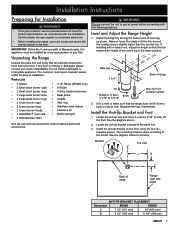
... and over the back of the island trim and slide the trim off the unit. Installation Instructions Installing an ERV Raised Vent (Optional) Install the ERV raised vent before making the range gas and electrical connections. • Dacor recommends that the 24 inch backguard be given to the lower flange in the cutout and...
... and over the back of the island trim and slide the trim off the unit. Installation Instructions Installing an ERV Raised Vent (Optional) Install the ERV raised vent before making the range gas and electrical connections. • Dacor recommends that the 24 inch backguard be given to the lower flange in the cutout and...
Installation Instructions
Page 11
..., 5 places Removing the Oven Door WARNING • Do not attempt to about a 15° angle from the range. NOTE: When installing a backguard, always install it away from the kit. Open the door to reduce weight. 1. Hold the door with the door(s) removed from the vertical position. ...of the backguard. Insert the screws through the holes in place with the eight (8) existing hex screws. Backguard Hex screw, 8 places Backguard Installation 7. See page 8. Fasten the backguard and the stainless steel trim piece in the back side of the range with the five (5) existing ...
..., 5 places Removing the Oven Door WARNING • Do not attempt to about a 15° angle from the range. NOTE: When installing a backguard, always install it away from the kit. Open the door to reduce weight. 1. Hold the door with the door(s) removed from the vertical position. ...of the backguard. Insert the screws through the holes in place with the eight (8) existing hex screws. Backguard Hex screw, 8 places Backguard Installation 7. See page 8. Fasten the backguard and the stainless steel trim piece in the back side of the range with the five (5) existing ...

Installation Instructions
Page 12
...wiring. WARNING Do not connect the green appliance wire to the L1 power supply terminal. 8. Remove the range electrical access cover from improper installation. • Connect the ground terminal (or lead) on the following pages give directions for use in an electric shock hazard. NOTE: Ranges... relief nut over the wires and thread it from the conduit strain relief (not included). 4. Dacor is long enough to allow the range to the range rating label (see page 14. 1. If installing a pre-wired range, skip to the L2 power supply terminal. 9. Connect the white wire to...
...wiring. WARNING Do not connect the green appliance wire to the L1 power supply terminal. 8. Remove the range electrical access cover from improper installation. • Connect the ground terminal (or lead) on the following pages give directions for use in an electric shock hazard. NOTE: Ranges... relief nut over the wires and thread it from the conduit strain relief (not included). 4. Dacor is long enough to allow the range to the range rating label (see page 14. 1. If installing a pre-wired range, skip to the L2 power supply terminal. 9. Connect the white wire to...
Installation Instructions
Page 13
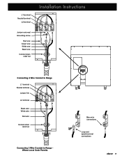
L1 terminal Neutral terminal L2 terminal Installation Instructions Jumper removed Grounding screw Red wire Green wire White wire Black wire Conduit strain relief nut Connecting 4 Wire Conduit to Range L1 terminal Neutral terminal Jumper link L2 terminal Black wire White wire Red wire Conduit strain relief nut Connecting 3 Wire Conduit to Range Where Local Code Permits Bare wire connections Loop and spade terminal connections 11
L1 terminal Neutral terminal L2 terminal Installation Instructions Jumper removed Grounding screw Red wire Green wire White wire Black wire Conduit strain relief nut Connecting 4 Wire Conduit to Range L1 terminal Neutral terminal Jumper link L2 terminal Black wire White wire Red wire Conduit strain relief nut Connecting 3 Wire Conduit to Range Where Local Code Permits Bare wire connections Loop and spade terminal connections 11
Installation Instructions
Page 14
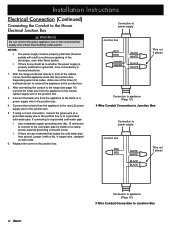
... the electrodes, even after flame ignition. ◊ If there is properly polarized or grounded, have it with a No. 4 copper wire, clamped on the junction box. Installation Instructions Electrical Connection (Continued) Connecting the Conduit to the House Electrical Junction Box WARNING Do not connect the green appliance wire to the junction box...
... the electrodes, even after flame ignition. ◊ If there is properly polarized or grounded, have it with a No. 4 copper wire, clamped on the junction box. Installation Instructions Electrical Connection (Continued) Connecting the Conduit to the House Electrical Junction Box WARNING Do not connect the green appliance wire to the junction box...

Installation Instructions
Page 15
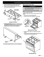
Installation Instructions Connection to power supply Junction box Separate No. 10 (minimum) copper grounding wire Fasten clamp tightly on pipe Wire nut 4 places Connection to appliance (Page 10) 4 Wire Conduit Connection to Junction Box with External Ground No. 4 copper wire Meter Metal water pipe Clamps Bare metal Insulated Pipe Jumper 13
Installation Instructions Connection to power supply Junction box Separate No. 10 (minimum) copper grounding wire Fasten clamp tightly on pipe Wire nut 4 places Connection to appliance (Page 10) 4 Wire Conduit Connection to Junction Box with External Ground No. 4 copper wire Meter Metal water pipe Clamps Bare metal Insulated Pipe Jumper 13