Product Manual
Page 1
Web/Installation Guide Product Model: TM DWS/DXS-3200 Series Layer 2+ Stackable Gigabit Ethernet Switches with optional XG uplinks Release 2.0 ©Copyright 2006. All rights reserved.
Web/Installation Guide Product Model: TM DWS/DXS-3200 Series Layer 2+ Stackable Gigabit Ethernet Switches with optional XG uplinks Release 2.0 ©Copyright 2006. All rights reserved.
Product Manual
Page 2
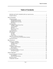
Table of Contents Table of Contents DXS/DWS-3227/3227P, DXS/DWS-3250 User Guide Overview 7 Intended Audience...8 Device Description ...9 Viewing the Device ...9 DXS-3250/DWS Front Panel ...9 DXS/DWS-3227 Front Panel ...10 DXS/DWS-3227P Front Panel...10 Back Panels...11 Ports Description ...12 1000Base-T ......26 Installing the Device ...27 Desktop or Shelf Installation ...27 Rack Installation ...27 Connecting the Device ...30 Connecting the Switch to a Terminal ...30 AC Power Connection ...30 Initial Configuration ...31 General Configuration Information 31 Auto-Negotiation ...31 Device Port Default...
Table of Contents Table of Contents DXS/DWS-3227/3227P, DXS/DWS-3250 User Guide Overview 7 Intended Audience...8 Device Description ...9 Viewing the Device ...9 DXS-3250/DWS Front Panel ...9 DXS/DWS-3227 Front Panel ...10 DXS/DWS-3227P Front Panel...10 Back Panels...11 Ports Description ...12 1000Base-T ......26 Installing the Device ...27 Desktop or Shelf Installation ...27 Rack Installation ...27 Connecting the Device ...30 Connecting the Switch to a Terminal ...30 AC Power Connection ...30 Initial Configuration ...31 General Configuration Information 31 Auto-Negotiation ...31 Device Port Default...
Product Manual
Page 3
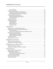
DXS/DSW 3200 Series User Guide Initial Configuration ...35 Advanced Configuration...38 Retrieving an IP Address From ...Password Recovery ...48 WLAN Licence Key ...48 Getting Started...51 Starting the D-Link Embedded Web Interface 52 Understanding the D-Link Embedded Web Interface 54 Device Representation...55 Using the D-Link Embedded Web Interface Management Buttons 56 Using Screen and Table Options 57 Adding Configuration... and Unit ID ...72 Removing and Replacing Stacking Members 73 Exchanging Stacking Members...74 Switching the Stacking Master ...74 Configuring Stacking ...75 Page 2
DXS/DSW 3200 Series User Guide Initial Configuration ...35 Advanced Configuration...38 Retrieving an IP Address From ...Password Recovery ...48 WLAN Licence Key ...48 Getting Started...51 Starting the D-Link Embedded Web Interface 52 Understanding the D-Link Embedded Web Interface 54 Device Representation...55 Using the D-Link Embedded Web Interface Management Buttons 56 Using Screen and Table Options 57 Adding Configuration... and Unit ID ...72 Removing and Replacing Stacking Members 73 Exchanging Stacking Members...74 Switching the Stacking Master ...74 Configuring Stacking ...75 Page 2
Product Manual
Page 10
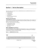
... front panel for the following: • DXS-3250/DWS Front Panel • DXS/DWS-3227 Front Panel • DXS- 3227P Front Panel • Back Panels DXS-3250/DWS Front Panel The D-Link DXS/DWS-3250 is performed via an RS-232 interface. The device configuration is a 48 port Gigabit Ethernet Managed Switch. This section contains descriptions for network... • Cable Specifications • LED Definitions • Cable, Port, and Pinout Information • Physical Dimensions Viewing the Device The devices described in this section are stackable Gigabit Ethernet Managed Switches.
... front panel for the following: • DXS-3250/DWS Front Panel • DXS/DWS-3227 Front Panel • DXS- 3227P Front Panel • Back Panels DXS-3250/DWS Front Panel The D-Link DXS/DWS-3250 is performed via an RS-232 interface. The device configuration is a 48 port Gigabit Ethernet Managed Switch. This section contains descriptions for network... • Cable Specifications • LED Definitions • Cable, Port, and Pinout Information • Physical Dimensions Viewing the Device The devices described in this section are stackable Gigabit Ethernet Managed Switches.
Product Manual
Page 11
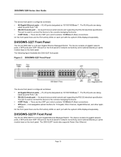
The port is used to connect the device to the console managing the device. • 4 SFP Ports - DXS/DWS-3227 Front Panel The D-Link DXS-3227 is a 24 port Gigabit Ethernet Managed Switch. RJ-45 ports designated as ports Ports 1-24. • RS-232 Console port - nated as 10/100/1000Base-T . ...interface for network connectivity, and 2 optional stacking or uplink module bays on the back panel. cations. DXS/DWS-3227P Front Panel The D-Link DXS-3227P is a 24 port Gigabit Ethernet Managed Switch. The device contains 24 gigabit network ports, 4 SFP ports and 1XFP 10G port on the front panel...
The port is used to connect the device to the console managing the device. • 4 SFP Ports - DXS/DWS-3227 Front Panel The D-Link DXS-3227 is a 24 port Gigabit Ethernet Managed Switch. RJ-45 ports designated as ports Ports 1-24. • RS-232 Console port - nated as 10/100/1000Base-T . ...interface for network connectivity, and 2 optional stacking or uplink module bays on the back panel. cations. DXS/DWS-3227P Front Panel The D-Link DXS-3227P is a 24 port Gigabit Ethernet Managed Switch. The device contains 24 gigabit network ports, 4 SFP ports and 1XFP 10G port on the front panel...
Product Manual
Page 21
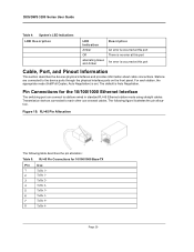
The following table describes the pin allocation: Table 5: RJ-45 Pin Connections for the 10/100/1000 Ethernet Interface The switching port can connect to the device ports through the physical interface ports on the front panel. Pin Connections for 10/100/1000 ... Page 20 For each other use crossed cables. Stations are connected to stations wired in standard RJ-45 Ethernet station mode using straight cables. DXS/DWS 3200 Series User Guide Table 4: System's LED Indications LED Description LED Indication Amber Off alternating Green and Amber Description An error is occurred...
The following table describes the pin allocation: Table 5: RJ-45 Pin Connections for the 10/100/1000 Ethernet Interface The switching port can connect to the device ports through the physical interface ports on the front panel. Pin Connections for 10/100/1000 ... Page 20 For each other use crossed cables. Stations are connected to stations wired in standard RJ-45 Ethernet station mode using straight cables. DXS/DWS 3200 Series User Guide Table 4: System's LED Indications LED Description LED Indication Amber Off alternating Green and Amber Description An error is occurred...
Product Manual
Page 26
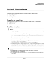
...same circuit as it from becoming unstable and/or falling over -current protection. These components are not blocked. • Do not install the switch in your system documentation. Opening or removing covers marked with a triangular symbol with the rating limit for Installation Section 2. To determine the ...their AC power connectors. Cautions • Ensure the air flow around the front, sides, and back of all devices installed on which the switch is placed should be serviced by trained service technicians only. • Ensure the power cable, extension cable, and/or plug is not ...
...same circuit as it from becoming unstable and/or falling over -current protection. These components are not blocked. • Do not install the switch in your system documentation. Opening or removing covers marked with a triangular symbol with the rating limit for Installation Section 2. To determine the ...their AC power connectors. Cautions • Ensure the air flow around the front, sides, and back of all devices installed on which the switch is placed should be serviced by trained service technicians only. • Ensure the power cable, extension cable, and/or plug is not ...
Product Manual
Page 28
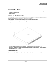
... the rubber feet installation on a surface, perform the following topics: • Desktop or Shelf Installation • Rack Installation Desktop or Shelf Installation When installing the switch on a flat surface or mounted in a wiring closet with the device should first be attached. Rack Installation The device can be mounted in an EIA...
... the rubber feet installation on a surface, perform the following topics: • Desktop or Shelf Installation • Rack Installation Desktop or Shelf Installation When installing the switch on a flat surface or mounted in a wiring closet with the device should first be attached. Rack Installation The device can be mounted in an EIA...
Product Manual
Page 31
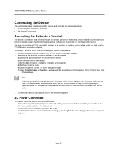
...cable to the device Console port, perform the following: 1. e) Under Properties, select VT100 for Function, Arrow, and Ctrl keys. DXS/DWS 3200 Series User Guide Connecting the Device This section describes how to connect the device, and includes the following sections: • Connecting ...the Switch to a Terminal • AC Power Connection Connecting the Switch to a Terminal The device is green. To connect a terminal to a grounded AC outlet. 3. Confirm that the...
...cable to the device Console port, perform the following: 1. e) Under Properties, select VT100 for Function, Arrow, and Ctrl keys. DXS/DWS 3200 Series User Guide Connecting the Device This section describes how to connect the device, and includes the following sections: • Connecting ...the Switch to a Terminal • AC Power Connection Connecting the Switch to a Terminal The device is green. To connect a terminal to a grounded AC outlet. 3. Confirm that the...
Product Manual
Page 32
... to do the following: • Advertise their abilities. Auto-negotiation is performed completely within the physical layers during link initiation, without any additional overhead to significant frame loss. The resulting mismatch may lead to either the MAC or higher...functions is not set with another device that is illustrated in the following topics: • General Configuration Information • Booting the Switch • Configuration Overview • Advanced Configuration • Software Download and Reboot • Configuring Stacking • Startup Menu Functions After...
... to do the following: • Advertise their abilities. Auto-negotiation is performed completely within the physical layers during link initiation, without any additional overhead to significant frame loss. The resulting mismatch may lead to either the MAC or higher...functions is not set with another device that is illustrated in the following topics: • General Configuration Information • Booting the Switch • Configuration Overview • Advanced Configuration • Software Download and Reboot • Configuring Stacking • Startup Menu Functions After...
Product Manual
Page 33
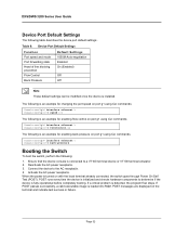
... problem is turned on port g1 using CLI commands. Console(config)# interface ethernet 1 Console(config-if)# back-pressure Booting the Switch To boot the switch, perform the following table describes the device port default settings:. POST runs every time the device is initialized and checks hardware components...Off Note These default settings can be modified once the device is loaded into RAM. Page 32 Deactivate the AC power receptacle. 3. DXS/DWS 3200 Series User Guide Device Port Default Settings The following : 1. The following is an example for changing the port speed on...
... problem is turned on port g1 using CLI commands. Console(config)# interface ethernet 1 Console(config-if)# back-pressure Booting the Switch To boot the switch, perform the following table describes the device port default settings:. POST runs every time the device is initialized and checks hardware components...Off Note These default settings can be modified once the device is loaded into RAM. Page 32 Deactivate the AC power receptacle. 3. DXS/DWS 3200 Series User Guide Device Port Default Settings The following : 1. The following is an example for changing the port speed on...
Product Manual
Page 34
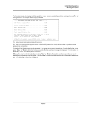
Autoboot in 2 seconds - Initial Configuration Booting the Switch As the switch boots, the bootup test first counts the device memory availability and then continues to run special procedures. D-Cache 8 KB. The boot process runs approximately 30 ...
Autoboot in 2 seconds - Initial Configuration Booting the Switch As the switch boots, the bootup test first counts the device memory availability and then continues to run special procedures. D-Cache 8 KB. The boot process runs approximately 30 ...
Product Manual
Page 35
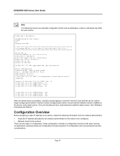
... it is completed Console> 01-Jan-200x 01:01:23 %LINK-I-Up: e1 01-Jan-200x 01:01:23 %LINK-W-Down: e2 01-Jan-200x 01:01:23 %LINK-I -InitCompleted: Initialization task is not the latest version, download and install the latest version. DXS/DWS 3200 Series User Guide Note The following information from...:01:22 %INIT-I -Up: Vlan 1 01-Jan-200x 01:01:23 %LINK-W-Down: e4 . . . 01-Jan-200x 01:01:23 %LINK-W-Down: e46 01-Jan-200x 01:01:23 %LINK-W-Down: e47 01-Jan-200x 01:01:23 %LINK-W-Down: e48 After the switch boots successfully, a system prompt appears (console>) and the local terminal can...
... it is completed Console> 01-Jan-200x 01:01:23 %LINK-I-Up: e1 01-Jan-200x 01:01:23 %LINK-W-Down: e2 01-Jan-200x 01:01:23 %LINK-I -InitCompleted: Initialization task is not the latest version, download and install the latest version. DXS/DWS 3200 Series User Guide Note The following information from...:01:22 %INIT-I -Up: Vlan 1 01-Jan-200x 01:01:23 %LINK-W-Down: e4 . . . 01-Jan-200x 01:01:23 %LINK-W-Down: e46 01-Jan-200x 01:01:23 %LINK-W-Down: e47 01-Jan-200x 01:01:23 %LINK-W-Down: e48 After the switch boots successfully, a system prompt appears (console>) and the local terminal can...
Product Manual
Page 36
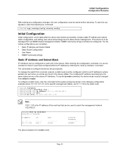
... in the device tables. If the device is an IP address to where packets are sent when no entries are port specific. To manage the switch from switch to router. Initial Configuration Configuration Overview After making any configuration changes, the new configuration must be configured, which starts after the device has booted...
... in the device tables. If the device is an IP address to where packets are sent when no entries are port specific. To manage the switch from switch to router. Initial Configuration Configuration Overview After making any configuration changes, the new configuration must be configured, which starts after the device has booted...
Product Manual
Page 37
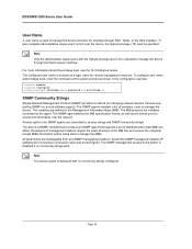
...controlled by access strings and SNMP community strings. Developers of management stations require the exact structure of standard and private MIB variables. DXS/DWS 3200 Series User Guide User Name A user name is used to manage the device. To configure user name and privilege ...Strings Simple Network Management Protocol (SNMP) provides a method for remote management sessions. Note The device switch is delivered with the highest privilege level (15) is allowed to the switch is disabled if no community strings configured. Note Only the administrator (super-user) with no community ...
...controlled by access strings and SNMP community strings. Developers of management stations require the exact structure of standard and private MIB variables. DXS/DWS 3200 Series User Guide User Name A user name is used to manage the device. To configure user name and privilege ...Strings Simple Network Management Protocol (SNMP) provides a method for remote management sessions. Note The device switch is delivered with the highest privilege level (15) is allowed to the switch is disabled if no community strings configured. Note Only the administrator (super-user) with no community ...
Product Manual
Page 38
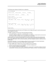
...; An option to configure IP address or not: If an IP address is to retrieve and modify MIB objects. The SNMP configuration options for the switch one (public community) with read-only access and the other (private community) with read and write) and IP address, as shown in accordance with the...
...; An option to configure IP address or not: If an IP address is to retrieve and modify MIB objects. The SNMP configuration options for the switch one (public community) with read-only access and the other (private community) with read and write) and IP address, as shown in accordance with the...
Product Manual
Page 40
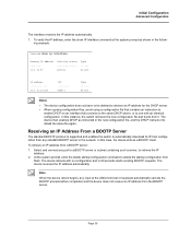
... the startup configuration from a BOOTP server: 1. Receiving an IP Address From a BOOTP Server The standard BOOTP protocol is supported and enables the switch to retrieve the IP address. 2. The device then enables DHCP as instructed in 60 seconds starts sending BOOTP requests. In this instance, the... switch retrieves the new configuration file and boots from the BOOTP server. The device reboots with an identical configuration. Note When the device reboot...
... the startup configuration from a BOOTP server: 1. Receiving an IP Address From a BOOTP Server The standard BOOTP protocol is supported and enables the switch to retrieve the IP address. 2. The device then enables DHCP as instructed in 60 seconds starts sending BOOTP requests. In this instance, the... switch retrieves the new configuration file and boots from the BOOTP server. The device reboots with an identical configuration. Note When the device reboot...
Product Manual
Page 43
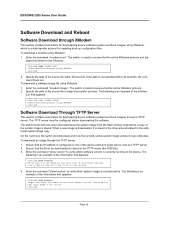
... bootvar Images currently available on the Flash Image-1 active (selected for downloading device software (system and boot images) using XMODEM. The switch boots and runs when decompressing the system image from the flash memory area where a copy of the source file within 20 seconds, ... must be sent to receive the file via the XModem protocol. 2. On the next boot, the switch decompresses and runs the currently active system image unless chosen otherwise. DXS/DWS 3200 Series User Guide Software Download and Reboot Software Download through a TFTP server. Enter the command...
... bootvar Images currently available on the Flash Image-1 active (selected for downloading device software (system and boot images) using XMODEM. The switch boots and runs when decompressing the system image from the flash memory area where a copy of the source file within 20 seconds, ... must be sent to receive the file via the XModem protocol. 2. On the next boot, the switch decompresses and runs the currently active system image unless chosen otherwise. DXS/DWS 3200 Series User Guide Software Download and Reboot Software Download through a TFTP server. Enter the command...
Product Manual
Page 44
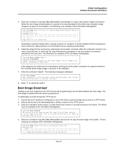
... 00:00:05 [hh:mm:ss] Page 43 Enter the command "copy tftp://{tftp address}/{file name}image" to copy a new system image to the switch. A period indicates that the copying process is an example of the information that the file to be sent to verify which boot version is in...). When the new image is downloaded, it into the flash updates the boot image. Enter the command "reload". The boot image is loaded when the switch is saved in a row indicate that appears: Console# boot system image-2 Console# sh bootvar Images currently available on . The following is timed out. ing is...
... 00:00:05 [hh:mm:ss] Page 43 Enter the command "copy tftp://{tftp address}/{file name}image" to copy a new system image to the switch. A period indicates that the copying process is an example of the information that the file to be sent to verify which boot version is in...). When the new image is downloaded, it into the flash updates the boot image. Enter the command "reload". The boot image is loaded when the switch is saved in a row indicate that appears: Console# boot system image-2 Console# sh bootvar Images currently available on . The following is timed out. ing is...
Product Manual
Page 45
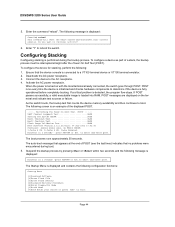
DXS/DWS 3200 Series User Guide 5. Deactivate the AC power receptacle. 3. Activate the AC power receptacle.... AC receptacle. 4. POST messages are displayed on with the local terminal already connected, the switch goes through POST. press RETURN or Esc. POST runs every time the device is fully operational before completely booting....Autoboot in 2 seconds -press RETURN or Esc.to abort and enter prom. Configuring Stacking Configuring stacking is connected to reboot the switch. The auto-boot message that appears at the end of POST (see the last lines) indicates that the device console is...
DXS/DWS 3200 Series User Guide 5. Deactivate the AC power receptacle. 3. Activate the AC power receptacle.... AC receptacle. 4. POST messages are displayed on with the local terminal already connected, the switch goes through POST. press RETURN or Esc. POST runs every time the device is fully operational before completely booting....Autoboot in 2 seconds -press RETURN or Esc.to abort and enter prom. Configuring Stacking Configuring stacking is connected to reboot the switch. The auto-boot message that appears at the end of POST (see the last lines) indicates that the device console is...

