User Guide
Page 14
... how you can connect the DGS-3204 to manage the Switch. ♦ Chapter 6, Using the Console Interface. Talks about Local Console Management via the RS-232 DCE console port and other aspects about how to your Gigabit Ethernet network. ♦ Chapter 5, Switch Management. Lists the technical specifications of the DGS-3204. Gigabit Ethernet Switch User's Guide ♦ Chapter...
... how you can connect the DGS-3204 to manage the Switch. ♦ Chapter 6, Using the Console Interface. Talks about Local Console Management via the RS-232 DCE console port and other aspects about how to your Gigabit Ethernet network. ♦ Chapter 5, Switch Management. Lists the technical specifications of the DGS-3204. Gigabit Ethernet Switch User's Guide ♦ Chapter...
User Guide
Page 18
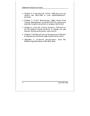
...Switch User's Guide Features The DGS-3204 Gigabit Ethernet Switch was designed for easy installation and high performance in an environment where traffic on the network and the number of -band management. Switch features include: Ports ♦ Four Gigabit Ethernet ports of fixed 1000BASE-SX multi-mode fiber interface. ♦ RS-232 DCE console port for diagnosing the Switch..., runts, etc. at 1,488,100pps per port at 100% of wire-speed for 1000Mbps speed. 4 Introduction Performance features ♦ Store and forward switching scheme capability to support rate adaptation and protocol ...
...Switch User's Guide Features The DGS-3204 Gigabit Ethernet Switch was designed for easy installation and high performance in an environment where traffic on the network and the number of -band management. Switch features include: Ports ♦ Four Gigabit Ethernet ports of fixed 1000BASE-SX multi-mode fiber interface. ♦ RS-232 DCE console port for diagnosing the Switch..., runts, etc. at 1,488,100pps per port at 100% of wire-speed for 1000Mbps speed. 4 Introduction Performance features ♦ Store and forward switching scheme capability to support rate adaptation and protocol ...

User Guide
Page 19
...), RMON MIB (RFC 1757), and MIB-II (RFC 1213). Out-of -band control via SNMP based software. ♦ Flash memory for software upgrade. Gigabit Ethernet Switch User's Guide ♦ 12K active MAC address entry table per device with automatic learning and aging. ♦ 8 MB packet buffer per device. ♦ Supports broadcast...
...), RMON MIB (RFC 1757), and MIB-II (RFC 1213). Out-of -band control via SNMP based software. ♦ Flash memory for software upgrade. Gigabit Ethernet Switch User's Guide ♦ 12K active MAC address entry table per device with automatic learning and aging. ♦ 8 MB packet buffer per device. ♦ Supports broadcast...

User Guide
Page 24
Power Failure As a precaution, the Switch should respond as follows: ♦ The Power LED indicator will light while the Switch loads onboard software and blinks when performing a self-test. ♦ The Console LED indicator will remain ON if there is a connection at the RS-232 port, otherwise this LED indicator is ...OFF. When power is resumed, plug the Switch back in case of power failure. After the device is powered on without having any or all LAN segment...
Power Failure As a precaution, the Switch should respond as follows: ♦ The Power LED indicator will light while the Switch loads onboard software and blinks when performing a self-test. ♦ The Console LED indicator will remain ON if there is a connection at the RS-232 port, otherwise this LED indicator is ...OFF. When power is resumed, plug the Switch back in case of power failure. After the device is powered on without having any or all LAN segment...

User Guide
Page 25
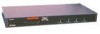
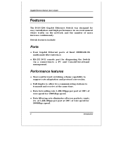
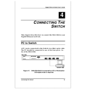
Front panel view of 4 1000BASE-SX multi-mode fiber ports, an RS-232 communication port, and LED indicators. Figure 3-1. Gigabit Ethernet Switch User's Guide 3 3 IDENTIFYING EXTERNAL COMPONENTS This chapter describes the front panel, rear panel and LED indicators of the Switch Front Panel The front panel of the Switch consists of the DGS-3204 Switch Identifying External Components 11
Front panel view of 4 1000BASE-SX multi-mode fiber ports, an RS-232 communication port, and LED indicators. Figure 3-1. Gigabit Ethernet Switch User's Guide 3 3 IDENTIFYING EXTERNAL COMPONENTS This chapter describes the front panel, rear panel and LED indicators of the Switch Front Panel The front panel of the Switch consists of the DGS-3204 Switch Identifying External Components 11

User Guide
Page 26
... AC power connector. Rear panel view of the DGS- ♦ AC Power Connector This is a three-pronged connector that display the conditions of the Switch and status of the network. Rear Panel The rear panel of the Switch consists of these LED indicators follows (see LED Indicators...). Figure 3-2. Gigabit Ethernet Switch User's Guide ♦ Four Gigabit Ethernet ports of fixed 1000BASE-SX multi-mode fiber interface. ♦ RS-232 DCE console port for diagnosing the Switch via a connection to a PC and Local Console Management. ♦ ...
... AC power connector. Rear panel view of the DGS- ♦ AC Power Connector This is a three-pronged connector that display the conditions of the Switch and status of the network. Rear Panel The rear panel of the Switch consists of these LED indicators follows (see LED Indicators...). Figure 3-2. Gigabit Ethernet Switch User's Guide ♦ Four Gigabit Ethernet ports of fixed 1000BASE-SX multi-mode fiber interface. ♦ RS-232 DCE console port for diagnosing the Switch via a connection to a PC and Local Console Management. ♦ ...

User Guide
Page 28
... is lit. These LED indicators are illuminated when a port is a secure connection (or link) to a device at a port. ♦ Full These LED indicators are lighted up when there is operating in full-duplex mode. 14 Identifying External Components Gigabit Ethernet Switch User's Guide Figure 3-3. The DGS-3204 Switch LED indicators ♦ Power After turning on the power...
... is lit. These LED indicators are illuminated when a port is a secure connection (or link) to a device at a port. ♦ Full These LED indicators are lighted up when there is operating in full-duplex mode. 14 Identifying External Components Gigabit Ethernet Switch User's Guide Figure 3-3. The DGS-3204 Switch LED indicators ♦ Power After turning on the power...
User Guide
Page 29
Figure 4-1. Gigabit Ethernet Switch User's Guide 4 4 CONNECTING THE SWITCH This chapter describes how to connect the DGS-3204 to any of the four ports (1x 4x) of the DGS-3204. The PC should be connected to a PC or Workstation (full-duplex mode is required) Connecting The Switch 15 DGS-3204 Switch connected to the Switch via a fiber optic cable. PC to Switch A PC can be connected to your Gigabit Ethernet network.
Figure 4-1. Gigabit Ethernet Switch User's Guide 4 4 CONNECTING THE SWITCH This chapter describes how to connect the DGS-3204 to any of the four ports (1x 4x) of the DGS-3204. The PC should be connected to a PC or Workstation (full-duplex mode is required) Connecting The Switch 15 DGS-3204 Switch connected to the Switch via a fiber optic cable. PC to Switch A PC can be connected to your Gigabit Ethernet network.

User Guide
Page 31
... to be manipulated to the RS-232 console port. From the Main Menu screen of the console program, an Administrator or Normal User (defined in a Switch Management 17 Gigabit Ethernet Switch User's Guide 5 5 SWITCH MANAGEMENT Local Console Management Local console management involves the administration of the DGS-3204 Switch via a direct connection to manage, control and monitor...
... to be manipulated to the RS-232 console port. From the Main Menu screen of the console program, an Administrator or Normal User (defined in a Switch Management 17 Gigabit Ethernet Switch User's Guide 5 5 SWITCH MANAGEMENT Local Console Management Local console management involves the administration of the DGS-3204 Switch via a direct connection to manage, control and monitor...

User Guide
Page 32
...width: ◊ Stop bits: 9,600 none 8 bits 1 IP Addresses and SNMP Community Names Each Switch has its own IP Address, which is not located on the same network as 18 Switch Management Console port (RS-232 DCE) Out-of-band management requires connecting a PC (with an SNMP network manager or... set in the event of your networking address scheme. In addition, you can change the default Switch IP Address to the RS-232 DCE console port of the Switch. It is useful when the network management station is used for communication with a SNMP management platform) to meet the specification of...
...width: ◊ Stop bits: 9,600 none 8 bits 1 IP Addresses and SNMP Community Names Each Switch has its own IP Address, which is not located on the same network as 18 Switch Management Console port (RS-232 DCE) Out-of-band management requires connecting a PC (with an SNMP network manager or... set in the event of your networking address scheme. In addition, you can change the default Switch IP Address to the RS-232 DCE console port of the Switch. It is useful when the network management station is used for communication with a SNMP management platform) to meet the specification of...

User Guide
Page 33
..., you can set access rights of events that can be as serious as a reboot (someone accidentally turned OFF the Switch), or less serious like a port status change the default Community Name in the Switch and set in overseeing the maintenance of the network managers that alert you allow to avoid future failure or...
..., you can set access rights of events that can be as serious as a reboot (someone accidentally turned OFF the Switch), or less serious like a port status change the default Community Name in the Switch and set in overseeing the maintenance of the network managers that alert you allow to avoid future failure or...

User Guide
Page 34
... different from the Switch by setting a list of IP Addresses of the authorized network managers. The trap is not sent if a new root trap is sent for the same transition. ♦ Link Change Event This trap is sent whenever the link of a port changes from link up to link down to the ... ♦ Topology Change A Topology Change trap is sent by the Switch when any of its configured ports transitions from the Learning state to the Forwarding state, or from link down or from the Forwarding state to link up and initialized such that software settings are reconfigured and hardware systems are...
... different from the Switch by setting a list of IP Addresses of the authorized network managers. The trap is not sent if a new root trap is sent for the same transition. ♦ Link Change Event This trap is sent whenever the link of a port changes from link up to link down to the ... ♦ Topology Change A Topology Change trap is sent by the Switch when any of its configured ports transitions from the Learning state to the Forwarding state, or from link down or from the Forwarding state to link up and initialized such that software settings are reconfigured and hardware systems are...

User Guide
Page 35
... one by specifying the MIB's Object-Identity (OID) at the network manager. The Switch uses the standard MIB-II Management Information Base module. Examples of read-only variables are the Switch's IP Address, Spanning Tree Algorithm parameters, and port status. These MIBs may also be quite involved, since you can be retrieved by...
... one by specifying the MIB's Object-Identity (OID) at the network manager. The Switch uses the standard MIB-II Management Information Base module. Examples of read-only variables are the Switch's IP Address, Spanning Tree Algorithm parameters, and port status. These MIBs may also be quite involved, since you can be retrieved by...

User Guide
Page 36
...congestion on that has been automatically learned. 5. Explicit configuration of Switched Local Area Network topology. 22 Switch Management Example: if Port 1 receives a packet destined for Port 2, the Switch transmits that packet through Port 2 only, and transmits nothing through observation of being transmitted ...to all segments, are : 1. Aging out of filtering information that Switch, in order to other Ports on the network, because packets, instead of Switched Local Area Network traffic. 4. Calculation and configuration of static filtering information. 3....
...congestion on that has been automatically learned. 5. Explicit configuration of Switched Local Area Network topology. 22 Switch Management Example: if Port 1 receives a packet destined for Port 2, the Switch transmits that packet through Port 2 only, and transmits nothing through observation of being transmitted ...to all segments, are : 1. Aging out of filtering information that Switch, in order to other Ports on the network, because packets, instead of Switched Local Area Network traffic. 4. Calculation and configuration of static filtering information. 3....

User Guide
Page 38
... best switch among the switches in a higher priority for the switch, and thus increases it as the backup path. ♦ Automatic topology re-configuration When the path for which there is a backup path fails, the backup path will loop indefinitely. STA Operation Levels STA operates on two levels: the bridge level and the port...
... best switch among the switches in a higher priority for the switch, and thus increases it as the backup path. ♦ Automatic topology re-configuration When the path for which there is a backup path fails, the backup path will loop indefinitely. STA Operation Levels STA operates on two levels: the bridge level and the port...

User Guide
Page 39
... is a parameter that users can set. The Root Path Cost of all Switches have the same Root Path Cost, the switch with the lowest Port Identifier is the Root Port. ♦ Designated Port This is the port on each LAN segment, the attached Bridge that has the lowest Path Cost ... the Root Bridge. On the Port Level ♦ Root Port Each switch has a Root Port. The higher the Bridge Priority, the better the chance the Switch will be selected as the Root Port. It forwards data packets for which the switch is the Designated Bridge. ♦ Port Priority The smaller this number, ...
... is a parameter that users can set. The Root Path Cost of all Switches have the same Root Path Cost, the switch with the lowest Port Identifier is the Root Port. ♦ Designated Port This is the port on each LAN segment, the attached Bridge that has the lowest Path Cost ... the Root Bridge. On the Port Level ♦ Root Port Each switch has a Root Port. The higher the Bridge Priority, the better the chance the Switch will be selected as the Root Port. It forwards data packets for which the switch is the Designated Bridge. ♦ Port Priority The smaller this number, ...

User Guide
Page 41
... 30 seconds. The decision to Bridge 1...and so on the STA calculation of three Bridges (or the Switch) connected in a loop is the time any port on the Switch spends in a loop, causing a serious network failure. Switch Management 27 Observe the following formulas when you can anticipate some major network problems if the STA...
... 30 seconds. The decision to Bridge 1...and so on the STA calculation of three Bridges (or the Switch) connected in a loop is the time any port on the Switch spends in a loop, causing a serious network failure. Switch Management 27 Observe the following formulas when you can anticipate some major network problems if the STA...

User Guide
Page 42
However, if you are advised to Table 5-1. Therefore, you need to customize the STA parameters, refer to keep the default factory settings and STA will automatically assign root bridges/ports and block loop connections. Before Applying the STA Rule 28 Switch Management Figure 5-1. Gigabit Ethernet Switch User's Guide STA setup can be somewhat complex.
However, if you are advised to Table 5-1. Therefore, you need to customize the STA parameters, refer to keep the default factory settings and STA will automatically assign root bridges/ports and block loop connections. Before Applying the STA Rule 28 Switch Management Figure 5-1. Gigabit Ethernet Switch User's Guide STA setup can be somewhat complex.

User Guide
Page 44
...STA parameter 30 Switch Management High # delays the change in workgroup priorit Bridg level of Avoid, if the switch is not received Root Bridge 4 - 30 sec. No effect, if not Root Bridge Never set greater than Max. Age Time Forward Delay Enable / Disable Port Priority lower the ...#, Increases chance of a large network 1 - 10 sec. Gigabit Ethernet Switch User's Guide STA parameters Settings Effects Comment Bridge Priority Hello Time Max. Compete for Root Avoid ...
...STA parameter 30 Switch Management High # delays the change in workgroup priorit Bridg level of Avoid, if the switch is not received Root Bridge 4 - 30 sec. No effect, if not Root Bridge Never set greater than Max. Age Time Forward Delay Enable / Disable Port Priority lower the ...#, Increases chance of a large network 1 - 10 sec. Gigabit Ethernet Switch User's Guide STA parameters Settings Effects Comment Bridge Priority Hello Time Max. Compete for Root Avoid ...

User Guide
Page 46
... changed by typing in a VT-100 compatible terminal mode) to erase characters behind and in can be used 32 Using the Console Interface Gigabit Ethernet Switch User's Guide ♦ VT-100/ANSI compatible ♦ Arrow keys enabled ♦ 9,600 baud ♦ 8 data bits ♦ No parity ♦ One ... in [square brackets]can be toggled on or off using the space bar, excepting the entries on the Port Configuration screen . 2. All of the screens are for your Switch, you can also access the same functions over a TELNET interface. Once you have set an IP address for the most part ...
... changed by typing in a VT-100 compatible terminal mode) to erase characters behind and in can be used 32 Using the Console Interface Gigabit Ethernet Switch User's Guide ♦ VT-100/ANSI compatible ♦ Arrow keys enabled ♦ 9,600 baud ♦ 8 data bits ♦ No parity ♦ One ... in [square brackets]can be toggled on or off using the space bar, excepting the entries on the Port Configuration screen . 2. All of the screens are for your Switch, you can also access the same functions over a TELNET interface. Once you have set an IP address for the most part ...


