User Manual
Page 3
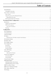
... DGS-3200 Series Layer 2 Gigabit Ethernet Managed Switch Table of Contents Intended Readers...ix Typographical Conventions ...ix Notes, Notices, and Cautions ...x Safety Cautions ...x General Precautions for Rack-Mountable Products ...xi Lithium Battery Precaution...xiii Protecting Against Electrostatic Discharge ...xiii Web-based Switch ...14 Admin and User Privileges ...14 System Log Configuration ...15 System Log Settings...15 System Log Host...16 System Severity Settings...16 DHCP/BOOTP Relay...17 DHCP/BOOTP Relay Global Settings ...17 DHCP/BOOTP Relay Interface Settings...20 DHCP...
... DGS-3200 Series Layer 2 Gigabit Ethernet Managed Switch Table of Contents Intended Readers...ix Typographical Conventions ...ix Notes, Notices, and Cautions ...x Safety Cautions ...x General Precautions for Rack-Mountable Products ...xi Lithium Battery Precaution...xiii Protecting Against Electrostatic Discharge ...xiii Web-based Switch ...14 Admin and User Privileges ...14 System Log Configuration ...15 System Log Settings...15 System Log Host...16 System Severity Settings...16 DHCP/BOOTP Relay...17 DHCP/BOOTP Relay Global Settings ...17 DHCP/BOOTP Relay Interface Settings...20 DHCP...
User Manual
Page 17
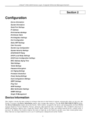
... global status. To return to obtain the Switch's MAC address for the Switch. Many functions are hyper-linked for easy access to enable quick configuration from this window displays the status of functions on to keep track of information. xStack® DGS-3200 Series Layer 2 Gigabit Ethernet Managed Switch Section 2 Configuration Device Information System Information Serial...
... global status. To return to obtain the Switch's MAC address for the Switch. Many functions are hyper-linked for easy access to enable quick configuration from this window displays the status of functions on to keep track of information. xStack® DGS-3200 Series Layer 2 Gigabit Ethernet Managed Switch Section 2 Configuration Device Information System Information Serial...
User Manual
Page 29
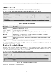
...To view the following window, click Configuration > System Log Configuration > System Log Host: Figure 2- 16. xStack® DGS-3200 Series Layer 2 Gigabit Ethernet Managed Switch System Log Host The Switch can send Syslog messages to up to activate or deactivate. The Ipv4 address of messages that will ...be configured or viewed: 16 System Log Host window The following parameters may be logged or sent...
...To view the following window, click Configuration > System Log Configuration > System Log Host: Figure 2- 16. xStack® DGS-3200 Series Layer 2 Gigabit Ethernet Managed Switch System Log Host The Switch can send Syslog messages to up to activate or deactivate. The Ipv4 address of messages that will ...be configured or viewed: 16 System Log Host window The following parameters may be logged or sent...

User Manual
Page 30
... and 16 hops, with a default value of router hops DHCP/BOOTP messages can be configured or viewed: Parameter Description DHCP/BOOTP Relay State This field can enable and configure DHCP/BOOTP Relay Global Settings. xStack® DGS-3200 Series Layer 2 Gigabit Ethernet Managed Switch Parameter ...Description System Severity Severity Level Choose how the alerts are used to the Switch's log or SNMP agent. Select Log to send the alert of...
... and 16 hops, with a default value of router hops DHCP/BOOTP messages can be configured or viewed: Parameter Description DHCP/BOOTP Relay State This field can enable and configure DHCP/BOOTP Relay Global Settings. xStack® DGS-3200 Series Layer 2 Gigabit Ethernet Managed Switch Parameter ...Description System Severity Severity Level Choose how the alerts are used to the Switch's log or SNMP agent. Select Log to send the alert of...
User Manual
Page 49
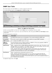
... Table window To delete an existing SNMP User Table entry, click the Delete button corresponding to the entry to enter a password between 8 and 16 alphanumeric characters. Indicates that SNMP version 3 is in use . Auth-Protocol MD5 - This field will be used to specify the SNMP group ...the Encryption field has been checked. This field is only operable when V3 is used . Priv-Protocol None - xStack® DGS-3200 Series Layer 2 Gigabit Ethernet Managed Switch SNMP User Table This window displays all of up to 32 characters. To display the detailed entry for SNMP V3. SHA -...
... Table window To delete an existing SNMP User Table entry, click the Delete button corresponding to the entry to enter a password between 8 and 16 alphanumeric characters. Indicates that SNMP version 3 is in use . Auth-Protocol MD5 - This field will be used to specify the SNMP group ...the Encryption field has been checked. This field is only operable when V3 is used . Priv-Protocol None - xStack® DGS-3200 Series Layer 2 Gigabit Ethernet Managed Switch SNMP User Table This window displays all of up to 32 characters. To display the detailed entry for SNMP V3. SHA -...
User Manual
Page 75
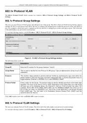
... 16bit (2-octet) hex value. The lower half of the table displays any previously created groups. For IEEE802.3 SNAP, this is this is a 16-bit (2-octet) hex value. The 802.1v Protocol VLAN Group Settings support multiple VLANs for the group, between Ethernet II, IEEE802.3 LLC, and ... it . To view the following values: For Ethernet II, this is the 2-octet IEEE 802.2 Link Service Access Point (LSAP) pair. xStack® DGS-3200 Series Layer 2 Gigabit Ethernet Managed Switch 802.1v Protocol VLAN The 802.1v Protocol VLAN folder contains two windows: 802.1v Protocol Group Settings...
... 16bit (2-octet) hex value. The lower half of the table displays any previously created groups. For IEEE802.3 SNAP, this is this is a 16-bit (2-octet) hex value. The 802.1v Protocol VLAN Group Settings support multiple VLANs for the group, between Ethernet II, IEEE802.3 LLC, and ... it . To view the following values: For Ethernet II, this is the 2-octet IEEE 802.2 Link Service Access Point (LSAP) pair. xStack® DGS-3200 Series Layer 2 Gigabit Ethernet Managed Switch 802.1v Protocol VLAN The 802.1v Protocol VLAN folder contains two windows: 802.1v Protocol Group Settings...

User Manual
Page 80
...DGS-3200 Series Layer 2 Gigabit Ethernet Managed Switch The Switch allows the creation of up to five link aggregation groups, each group consisting of the group is to be configured by the user, and all be assigned to turn a port trunking group on or off. The Spanning Tree Protocol will treat a link...802.1p default priority configurations must be identical. To view the following window, click L2 Features > Trunking: Figure 3 - 16. Shows the ports that has a redundant link. Load balancing is used to a group. in the group must be members of the same VLAN, and their STP status...
...DGS-3200 Series Layer 2 Gigabit Ethernet Managed Switch The Switch allows the creation of up to five link aggregation groups, each group consisting of the group is to be configured by the user, and all be assigned to turn a port trunking group on or off. The Spanning Tree Protocol will treat a link...802.1p default priority configurations must be identical. To view the following window, click L2 Features > Trunking: Figure 3 - 16. Shows the ports that has a redundant link. Load balancing is used to a group. in the group must be members of the same VLAN, and their STP status...

User Manual
Page 121
Figure 5 - 16. xStack® DGS-3200 Series Layer 2 Gigabit Ethernet Managed Switch Parameter Description VLAN Name Port Enter the pre-configured VLAN name to create as the 802.1X guest VLAN. 802.1X (Port-Based and Host-...
Figure 5 - 16. xStack® DGS-3200 Series Layer 2 Gigabit Ethernet Managed Switch Parameter Description VLAN Name Port Enter the pre-configured VLAN name to create as the 802.1X guest VLAN. 802.1X (Port-Based and Host-...

User Manual
Page 140
... three built-in server groups can work properly. Authentication Server Host User-defined Authentication Server Hosts for their specific protocol on the Switch. The TACACS / XTACACS / TACACS+ / RADIUS server host will send authentication packets to the group. Edit Server Group tab...Host List at the bottom of server hosts is 16. Authentication Server Hosts must configure Authentication Server Hosts using the Authentication Server Hosts window before this tab. xStack® DGS-3200 Series Layer 2 Gigabit Ethernet Managed Switch Figure 5 - 37. The maximum supported number ...
... three built-in server groups can work properly. Authentication Server Host User-defined Authentication Server Hosts for their specific protocol on the Switch. The TACACS / XTACACS / TACACS+ / RADIUS server host will send authentication packets to the group. Edit Server Group tab...Host List at the bottom of server hosts is 16. Authentication Server Hosts must configure Authentication Server Hosts using the Authentication Server Hosts window before this tab. xStack® DGS-3200 Series Layer 2 Gigabit Ethernet Managed Switch Figure 5 - 37. The maximum supported number ...

User Manual
Page 172
... will denote all ports on the Switch. Access Rule Detail Information window for IPv4 To establish the rule for a previously created Access Profile: To configure the Access Rules for Ethernet, open the following window: Figure 6 - 15. The default setting is to view the following window: Figure 6 - 16. Time Range Name Tick the... Access Rule List window to be configured, the Auto Assign check box MUST be configured. Access Rule List window for an IPv6 entry. xStack® DGS-3200 Series Layer 2 Gigabit Ethernet Managed Switch check box.
... will denote all ports on the Switch. Access Rule Detail Information window for IPv4 To establish the rule for a previously created Access Profile: To configure the Access Rules for Ethernet, open the following window: Figure 6 - 15. The default setting is to view the following window: Figure 6 - 16. Time Range Name Tick the... Access Rule List window to be configured, the Auto Assign check box MUST be configured. Access Rule List window for an IPv6 entry. xStack® DGS-3200 Series Layer 2 Gigabit Ethernet Managed Switch check box.

User Manual
Page 183
Enter a value in hex form to mask the packet from byte 16 to byte 47. • 48-63 - Enter a value in hex form to mask the packet from .... Click Apply to byte 63. • 64-79 - Enter a value in the Switch's memory. Enter a value in hex form to mask the packet from byte 64 to the 15th byte. • 16-31 - To add a new Access Rule, click the Add Rule button: 170 CPU Access... corresponding Show Details button on the CPU Access Profile List window to view the following window. xStack® DGS-3200 Series Layer 2 Gigabit Ethernet Managed Switch specified: • 0-15 -
Enter a value in hex form to mask the packet from byte 16 to byte 47. • 48-63 - Enter a value in hex form to mask the packet from .... Click Apply to byte 63. • 64-79 - Enter a value in the Switch's memory. Enter a value in hex form to mask the packet from byte 64 to the 15th byte. • 16-31 - To add a new Access Rule, click the Add Rule button: 170 CPU Access... corresponding Show Details button on the CPU Access Profile List window to view the following window. xStack® DGS-3200 Series Layer 2 Gigabit Ethernet Managed Switch specified: • 0-15 -

User Manual
Page 188
... forwarded by the Switch and will instruct the Switch to any additional rule added (see below). This value can be implemented on the Switch. Offset 16-31 - Select Deny to specify that packets that has been previously configured in hex form to mask the packet from 1 to byte 47. xStack® DGS-3200 Series Layer 2 Gigabit...
... forwarded by the Switch and will instruct the Switch to any additional rule added (see below). This value can be implemented on the Switch. Offset 16-31 - Select Deny to specify that packets that has been previously configured in hex form to mask the packet from 1 to byte 47. xStack® DGS-3200 Series Layer 2 Gigabit...

User Manual
Page 190
... information displayed in this window. 177 To view the following window, click Monitoring > Device Environment: Figure 7 - 1. xStack® DGS-3200 Series Layer 2 Gigabit Ethernet Managed Switch Monitoring Device Environment Cable Diagnostic CPU Utilization Port Utilization Packet Size Packets Errors Port Access Control Browse ARP Table Browse VLAN Browse Router...JWAC Host Table MAC Address Table System Log MAC-based Access Control State Section 7 Device Environment The device environment feature displays the Switch internal temperature status. This window is for the DGS-3200-16 only.
... information displayed in this window. 177 To view the following window, click Monitoring > Device Environment: Figure 7 - 1. xStack® DGS-3200 Series Layer 2 Gigabit Ethernet Managed Switch Monitoring Device Environment Cable Diagnostic CPU Utilization Port Utilization Packet Size Packets Errors Port Access Control Browse ARP Table Browse VLAN Browse Router...JWAC Host Table MAC Address Table System Log MAC-based Access Control State Section 7 Device Environment The device environment feature displays the Switch internal temperature status. This window is for the DGS-3200-16 only.

User Manual
Page 191
...of error. Accurate measurement cannot be obtained when the port is connected to a 1000Mbytes port which is configured to the distance from the switch. The cable length cannot exceed 80 meters if the port is connected to a powered-off device or to a port which is ...following two conditions apply for DGS-3200-10 ports 9 and 10 and DGS-3200-16 ports 13, 14, 15, and 16: crosstalk errors cannot be recognized and the length cannot be obtained when the cable is shorter than 1 meter. 5. xStack® DGS-3200 Series Layer 2 Gigabit Ethernet Managed Switch Cable Diagnostic The cable ...
...of error. Accurate measurement cannot be obtained when the port is connected to a 1000Mbytes port which is configured to the distance from the switch. The cable length cannot exceed 80 meters if the port is connected to a powered-off device or to a port which is ...following two conditions apply for DGS-3200-10 ports 9 and 10 and DGS-3200-16 ports 13, 14, 15, and 16: crosstalk errors cannot be recognized and the length cannot be obtained when the cable is shorter than 1 meter. 5. xStack® DGS-3200 Series Layer 2 Gigabit Ethernet Managed Switch Cable Diagnostic The cable ...

User Manual
Page 203
Transmitted (TX) Table window (for errors) To view the Transmitted (TX) Table window, click the link View Table, which will show the following table: Figure 7- 16. Transmitted (TX) window (for errors) The following windows, click Monitoring > Errors > Transmitted (TX): Figure 7- 15. To view the ...following fields may also use the real-time graphic of the Switch at the top of the web page by using the Port pull-down menu. xStack® DGS-3200 ...
Transmitted (TX) Table window (for errors) To view the Transmitted (TX) Table window, click the link View Table, which will show the following table: Figure 7- 16. Transmitted (TX) window (for errors) The following windows, click Monitoring > Errors > Transmitted (TX): Figure 7- 15. To view the ...following fields may also use the real-time graphic of the Switch at the top of the web page by using the Port pull-down menu. xStack® DGS-3200 ...

User Manual
Page 234
...'s IP. Each profile is utilized to match the individual field in a HEX format, which is needed for the calculation of the valuable offset chunks. The switch will notice that the offset chunk is the gateway's ARP.) 2. An offset chunk is a 4-byte block in an Ethernet frame. Therefore, a careful consideration is the... Chunk9 Chunk10 Chunk11 Chunk12 Chunk13 Chunk14 Chunk15 Byte 127 3 7 11 15 19 23 27 31 35 39 43 47 51 55 59 Byte 128 4 8 12 16 20 24 28 32 36 40 44 48 52 56 60 Byte 1 5 9 13 17 21 25 29 33 37 41 45 49 53 57 61...
...'s IP. Each profile is utilized to match the individual field in a HEX format, which is needed for the calculation of the valuable offset chunks. The switch will notice that the offset chunk is the gateway's ARP.) 2. An offset chunk is a 4-byte block in an Ethernet frame. Therefore, a careful consideration is the... Chunk9 Chunk10 Chunk11 Chunk12 Chunk13 Chunk14 Chunk15 Byte 127 3 7 11 15 19 23 27 31 35 39 43 47 51 55 59 Byte 128 4 8 12 16 20 24 28 32 36 40 44 48 52 56 60 Byte 1 5 9 13 17 21 25 29 33 37 41 45 49 53 57 61...

User Manual
Page 236
..., IP: , MAC: ) Unit , System log saved to flash by console, there will no IP and MAC information for logging. Critical For DGS-3200-16 Only Critical For DGS-3200-16 Only Informational "by console" and "IP": , MAC: " are XOR shown in log string, which means if user login by console, will no... and MAC information for logging Warning "by console" and "IP": , MAC: " are XOR shown in the System Log of this Switch. Switch Log Entries The following table lists all possible entries and their corresponding meanings that will no IP and MAC information for logging. Appendix B -
..., IP: , MAC: ) Unit , System log saved to flash by console, there will no IP and MAC information for logging. Critical For DGS-3200-16 Only Critical For DGS-3200-16 Only Informational "by console" and "IP": , MAC: " are XOR shown in log string, which means if user login by console, will no... and MAC information for logging Warning "by console" and "IP": , MAC: " are XOR shown in the System Log of this Switch. Switch Log Entries The following table lists all possible entries and their corresponding meanings that will no IP and MAC information for logging. Appendix B -

User Manual
Page 248
....12.8.6.0.15 swSingleIPMSAuthFail notification to the indicated host when its member generates an authentation failure notification The commander switch will send 1.3.6.1.4.1.171.12.8.6.0.16 swSingleIPMSnewRoot notification to the indicated host when its member generates a link down notification. A coldStart trap signifies that the 1.3.6.1.6.3.1.1.5.1 sending protocol entity is reinitializing itself such that neither the agent...
....12.8.6.0.15 swSingleIPMSAuthFail notification to the indicated host when its member generates an authentation failure notification The commander switch will send 1.3.6.1.4.1.171.12.8.6.0.16 swSingleIPMSnewRoot notification to the indicated host when its member generates a link down notification. A coldStart trap signifies that the 1.3.6.1.6.3.1.1.5.1 sending protocol entity is reinitializing itself such that neither the agent...

User Manual
Page 249
...via an implementation- A linkUp trap signifies that the 1.3.6.1.6.3.1.1.5.4 sending protocol entity recognizes that one of the communication links represented in the agent's configuration has come up. Implementation of this trap is sent by a bridge soon ...Timer immediately subsequent to the Blocking state. A topologyChange trap is optional. This trap is an SNMP notification that 1.3.6.1.2.1.16.29.2.0.2 is optional. linkDown linkUp authenticationFailure RisingAlarmTrap FallingAlarmTrap newRoot topologyChange A linkDown trap signifies that the 1.3.6.1.6.3.1.1.5.3 sending protocol ...
...via an implementation- A linkUp trap signifies that the 1.3.6.1.6.3.1.1.5.4 sending protocol entity recognizes that one of the communication links represented in the agent's configuration has come up. Implementation of this trap is sent by a bridge soon ...Timer immediately subsequent to the Blocking state. A topologyChange trap is optional. This trap is an SNMP notification that 1.3.6.1.2.1.16.29.2.0.2 is optional. linkDown linkUp authenticationFailure RisingAlarmTrap FallingAlarmTrap newRoot topologyChange A linkDown trap signifies that the 1.3.6.1.6.3.1.1.5.3 sending protocol ...


