
Product Manual
Page 2
...-based Management...22 Tool Bar > Save Menu ...23 i Table of Contents D-Link Web Smart Switch User Manual Table of Contents Table of Contents ...i About This Guide...1 Terms/Usage...1 Copyright and Trademarks ...1 Product Introduction ...2 DGS-1210-16 ...3 Front Panel ...3 Rear Panel...3 DGS-1210-24 ...3 Front Panel ...3 Rear Panel...4 DGS-1210-48 ...4 Front Panel ...4 Rear Panel...5 Hardware Installation ...6 Step 1: Unpacking...6 Step...
...-based Management...22 Tool Bar > Save Menu ...23 i Table of Contents D-Link Web Smart Switch User Manual Table of Contents Table of Contents ...i About This Guide...1 Terms/Usage...1 Copyright and Trademarks ...1 Product Introduction ...2 DGS-1210-16 ...3 Front Panel ...3 Rear Panel...3 DGS-1210-24 ...3 Front Panel ...3 Rear Panel...4 DGS-1210-48 ...4 Front Panel ...4 Rear Panel...5 Hardware Installation ...6 Step 1: Unpacking...6 Step...

Product Manual
Page 3
Table of Contents D-Link Web Smart Switch User Manual Save Configuration ...23 Save Log ...23 Tool Bar > Tool Menu ...23 Reset ...23 Reset System ...23 Reboot Device ...24 Configuration Backup & Restore ...> 802.1Q Management VLAN 35 Configuration > Voice VLAN > Voice VLAN Setting 35 Configuration > Voice VLAN > Voice VLAN OUI Setting 36 Configuration > Link Aggregation > Port Trunking 37 Configuration > Link Aggregation > LACP Port Settings 37 Configuration > IGMP Snooping ...38 Configuration > Port Mirroring ...39 Configuration > Power Saving...40 Configuration > Loopback Detection ...40...
Table of Contents D-Link Web Smart Switch User Manual Save Configuration ...23 Save Log ...23 Tool Bar > Tool Menu ...23 Reset ...23 Reset System ...23 Reboot Device ...24 Configuration Backup & Restore ...> 802.1Q Management VLAN 35 Configuration > Voice VLAN > Voice VLAN Setting 35 Configuration > Voice VLAN > Voice VLAN OUI Setting 36 Configuration > Link Aggregation > Port Trunking 37 Configuration > Link Aggregation > LACP Port Settings 37 Configuration > IGMP Snooping ...38 Configuration > Port Mirroring ...39 Configuration > Power Saving...40 Configuration > Loopback Detection ...40...
Product Manual
Page 4
... Functions ...62 Physical & Environment ...62 Emission (EMI) Certifications ...62 Safety Certifications...62 Features ...62 L2 Features ...62 VLAN ...62 QoS (Quality of Contents D-Link Web Smart Switch User Manual Command Line Interface...59 To connect a switch via TELNET:...59 Logging on to the Command Line Interface 59 CLI Commands: ...59 Download...59...
... Functions ...62 Physical & Environment ...62 Emission (EMI) Certifications ...62 Safety Certifications...62 Features ...62 L2 Features ...62 VLAN ...62 QoS (Quality of Contents D-Link Web Smart Switch User Manual Command Line Interface...59 To connect a switch via TELNET:...59 Logging on to the Command Line Interface 59 CLI Commands: ...59 Download...59...

Product Manual
Page 5
...trademarks and trade names may appear slightly different from the illustrations shown in any proprietary interest in this text: D-Link and the D-LINK logo are trademarks of D-Link Corporation; Smart Console Utility: An introduction to either the entities claiming the marks and names or their products. All... Information in trademarks and trade names other Ethernet switches. About This Guide D-Link Web Smart Switch User Manual About This Guide This guide provides instructions to install the D-Link Gigabit Web Smart Switch DGS-1210-16/24/48, how to use of the device. Note: The model you...
...trademarks and trade names may appear slightly different from the illustrations shown in any proprietary interest in this text: D-Link and the D-LINK logo are trademarks of D-Link Corporation; Smart Console Utility: An introduction to either the entities claiming the marks and names or their products. All... Information in trademarks and trade names other Ethernet switches. About This Guide D-Link Web Smart Switch User Manual About This Guide This guide provides instructions to install the D-Link Gigabit Web Smart Switch DGS-1210-16/24/48, how to use of the device. Note: The model you...

Product Manual
Page 6
... device integrity. ACL is a powerful tool to an assigned VLAN with a simple and easy management of 16, 24, and 48 ports. 1 Product Introduction D-Link Web Smart Switch User Manual 1 Product Introduction Thank you and congratulations on DGS-1210 series such as server or gateway devices. Choices of their network down to keep the network from...
... device integrity. ACL is a powerful tool to an assigned VLAN with a simple and easy management of 16, 24, and 48 ports. 1 Product Introduction D-Link Web Smart Switch User Manual 1 Product Introduction Thank you and congratulations on DGS-1210 series such as server or gateway devices. Choices of their network down to keep the network from...
Product Manual
Page 7
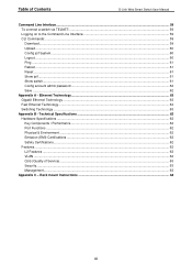
.../Speed LED (1-20, 21F, 22F, 23F, 24F, 21T, 22T, 23T, 24T): The Link/Act/Speed LED flashes, which indicates a network link through the corresponding port. NOTE: On DGS-1210-16, the SFP ports are shared with 4 Combo SFP Slot Web Smart Switch Front Panel Figure 3 - When it has a green ... for optical transceivers Power LED : The Power LED lights up when the Switch is running on 10M or 100M. 1 Product Introduction D-Link Web Smart Switch User Manual DGS-1210-16 16-Port 10/100/1000Mbps with 4 Combo SFP Slot Web Smart Switch Front Panel Figure 1 - Reset: By pressing the Reset button,...
.../Speed LED (1-20, 21F, 22F, 23F, 24F, 21T, 22T, 23T, 24T): The Link/Act/Speed LED flashes, which indicates a network link through the corresponding port. NOTE: On DGS-1210-16, the SFP ports are shared with 4 Combo SFP Slot Web Smart Switch Front Panel Figure 3 - When it has a green ... for optical transceivers Power LED : The Power LED lights up when the Switch is running on 10M or 100M. 1 Product Introduction D-Link Web Smart Switch User Manual DGS-1210-16 16-Port 10/100/1000Mbps with 4 Combo SFP Slot Web Smart Switch Front Panel Figure 1 - Reset: By pressing the Reset button,...

Product Manual
Page 8
...to reset the Switch back to the default settings. 1 Product Introduction D-Link Web Smart Switch User Manual sending or receiving data to the SFP port and linked up when the Switch is off when all fans work normally. DGS-1210-48 Front Panel SFP ports for optical transceivers Power LED : The Power... (1-44, 45F, 46F, 47F, 48F, 45T, 46T, 47T, 48T): The Link/Act/Speed LED flashes, which indicates a network link through the corresponding port. When the optical transceiver is running on 1000M. NOTE: On the DGS-1210-24, the SFP ports are shared with 4 Combo SFP Slot Web Smart Switch Front...
...to reset the Switch back to the default settings. 1 Product Introduction D-Link Web Smart Switch User Manual sending or receiving data to the SFP port and linked up when the Switch is off when all fans work normally. DGS-1210-48 Front Panel SFP ports for optical transceivers Power LED : The Power... (1-44, 45F, 46F, 47F, 48F, 45T, 46T, 47T, 48T): The Link/Act/Speed LED flashes, which indicates a network link through the corresponding port. When the optical transceiver is running on 1000M. NOTE: On the DGS-1210-24, the SFP ports are shared with 4 Combo SFP Slot Web Smart Switch Front...

Product Manual
Page 9
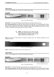
DGS-1210-48 Rear Panel Power: Connect the supplied AC power cable to this port. 5 1 Product Introduction D-Link Web Smart Switch User Manual Rear Panel Figure 6 -
DGS-1210-48 Rear Panel Power: Connect the supplied AC power cable to this port. 5 1 Product Introduction D-Link Web Smart Switch User Manual Rear Panel Figure 6 -

Product Manual
Page 10
...missing or damaged, please contact the local reseller for the D-Link Web-Smart Switch. Attach the adhesive rubber pads to the bottom Rack Installation The switch can be mounted in the User Manual to the Switch 6 Attach the mounting brackets to make sure...recommended that it . Make sure that these brackets are present and undamaged. Figure 8 - Figure 7 - 2 Hardware Installation D-Link Web Smart Switch User Manual 2 Hardware Installation This chapter provides unpacking and installation information for replacement. Please consult the packing list located in an EIA standard size...
...missing or damaged, please contact the local reseller for the D-Link Web-Smart Switch. Attach the adhesive rubber pads to the bottom Rack Installation The switch can be mounted in the User Manual to the Switch 6 Attach the mounting brackets to make sure...recommended that it . Make sure that these brackets are present and undamaged. Figure 8 - Figure 7 - 2 Hardware Installation D-Link Web Smart Switch User Manual 2 Hardware Installation This chapter provides unpacking and installation information for replacement. Please consult the packing list located in an EIA standard size...

Product Manual
Page 11
... earthing of rack-mounted equipment should be such that overloading of the circuits might have on overcurrent protection and supply wiring. 2 Hardware Installation D-Link Web Smart Switch User Manual Then, use of power strips)." C) Mechanical Loading - E) Reliable Earthing - Therefore, consideration should be given to the connection of the equipment to the supply...
... earthing of rack-mounted equipment should be such that overloading of the circuits might have on overcurrent protection and supply wiring. 2 Hardware Installation D-Link Web Smart Switch User Manual Then, use of power strips)." C) Mechanical Loading - E) Reliable Earthing - Therefore, consideration should be given to the connection of the equipment to the supply...
Product Manual
Page 12
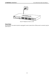
When power is resumed, plug the switch back in case of power failure. 2 Hardware Installation D-Link Web Smart Switch User Manual Figure 10 -Plugging the switch into an outlet Power Failure As a precaution, the switch should be unplugged in . 8
When power is resumed, plug the switch back in case of power failure. 2 Hardware Installation D-Link Web Smart Switch User Manual Figure 10 -Plugging the switch into an outlet Power Failure As a precaution, the switch should be unplugged in . 8

Product Manual
Page 13
... of your device: 1. The PC should have an IP address in the same range as the switch. 3 Getting Started D-Link Web Smart Switch User Manual 3 Getting Started This chapter introduces the management interface of the switch and to the Ethernet port on the PC. Using Web-...based Management After a successful physical installation, you want to manage multiple D-Link Web Smart Switches, the SmartConsole Utility is easier to ...
... of your device: 1. The PC should have an IP address in the same range as the switch. 3 Getting Started D-Link Web Smart Switch User Manual 3 Getting Started This chapter introduces the management interface of the switch and to the Ethernet port on the PC. Using Web-...based Management After a successful physical installation, you want to manage multiple D-Link Web Smart Switches, the SmartConsole Utility is easier to ...

Product Manual
Page 14
... switch. SmartConsole Utility The SmartConsole Utility included in the same subnet as it appears in the address bar. 3 Getting Started D-Link Web Smart Switch User Manual Login Web-based Management In order to login and configure the switch via an Ethernet connection, the PC must have an IP... Smart Wizard will guide you will automatically load the web configuration in the web browser NOTE: The switch's factory default IP address is manual installation. Web-based Management By clicking the Exit button in the Smart Wizard, you through the autorun program on the installation CD and ...
... switch. SmartConsole Utility The SmartConsole Utility included in the same subnet as it appears in the address bar. 3 Getting Started D-Link Web Smart Switch User Manual Login Web-based Management In order to login and configure the switch via an Ethernet connection, the PC must have an IP... Smart Wizard will guide you will automatically load the web configuration in the web browser NOTE: The switch's factory default IP address is manual installation. Web-based Management By clicking the Exit button in the Smart Wizard, you through the autorun program on the installation CD and ...
Product Manual
Page 15
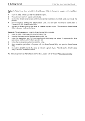
...desktop, click Run. 3. Upon completion, go to Start > Programs > D-Link SmartConsole Utility and open the utility by clicking Start > Programs > D-Link SmartConsole Utility. 5. In the Run dialog box, type D:\D-Link SmartConsole Utility\setup.exe (where D:\ represents the drive letter of SmartConsole's .... 4. For detailed explanations of your CD-Rom/DVD-Rom Drive. 2. 3 Getting Started D-Link Web Smart Switch User Manual Option 1: Follow these steps to install the SmartConsole Utility manually. 1. The autorun program will guide you can open the SmartConsole Utility. 6.
...desktop, click Run. 3. Upon completion, go to Start > Programs > D-Link SmartConsole Utility and open the utility by clicking Start > Programs > D-Link SmartConsole Utility. 5. In the Run dialog box, type D:\D-Link SmartConsole Utility\setup.exe (where D:\ represents the drive letter of SmartConsole's .... 4. For detailed explanations of your CD-Rom/DVD-Rom Drive. 2. 3 Getting Started D-Link Web Smart Switch User Manual Option 1: Follow these steps to install the SmartConsole Utility manually. 1. The autorun program will guide you can open the SmartConsole Utility. 6.
Product Manual
Page 16
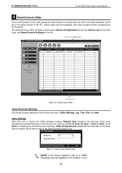
4 SmartConsole Utility D-Link Web Smart Switch User Manual 4 SmartConsole Utility The D-Link SmartConsole Utility allows the administrator to quickly discover all D-Link smart switches, which were selected as the main body, and SmartConsole Settings at the left has five icons, Utility Settings, Log, Trap, File, and Help. ...
4 SmartConsole Utility D-Link Web Smart Switch User Manual 4 SmartConsole Utility The D-Link SmartConsole Utility allows the administrator to quickly discover all D-Link smart switches, which were selected as the main body, and SmartConsole Settings at the left has five icons, Utility Settings, Log, Trap, File, and Help. ...

Product Manual
Page 17
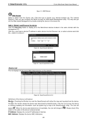
... indicates when the message was received, IP denotes where it comes from and Status shows the content of the SmartConsole Utility and the device. Figure 16 - Click View Trap to launch the Log window. SmartConsole Trap The trap icon in the SmartConsole Settings will not be discovered. Please see below for.../Time indicates when the trap message was received File By clicking on this log message. Click Clear Log to launch the Trap window. 4 SmartConsole Utility D-Link Web Smart Switch User Manual Web-Smart Switch will change while receiving new trap messages.
... indicates when the message was received, IP denotes where it comes from and Status shows the content of the SmartConsole Utility and the device. Figure 16 - Click View Trap to launch the Log window. SmartConsole Trap The trap icon in the SmartConsole Settings will not be discovered. Please see below for.../Time indicates when the trap message was received File By clicking on this log message. Click Clear Log to launch the Trap window. 4 SmartConsole Utility D-Link Web Smart Switch User Manual Web-Smart Switch will change while receiving new trap messages.

Product Manual
Page 18
Monitor Save As: Records the setting of the Device List as default for the next time the SmartConsole Utility is used. Figure 19 - Help Click this icon to launch the SmartConsole Info window. 4 SmartConsole Utility D-Link Web Smart Switch User Manual Figure 18 - Monitor Load: Manually load a Device List setting file. SmartConsole File Monitor Save: Records the setting of the Device List in an appointed filename and file path. SmartConsole Help 14
Monitor Save As: Records the setting of the Device List as default for the next time the SmartConsole Utility is used. Figure 19 - Help Click this icon to launch the SmartConsole Info window. 4 SmartConsole Utility D-Link Web Smart Switch User Manual Figure 18 - Monitor Load: Manually load a Device List setting file. SmartConsole File Monitor Save: Records the setting of the Device List in an appointed filename and file path. SmartConsole Help 14
Product Manual
Page 19
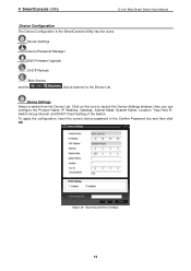
4 SmartConsole Utility D-Link Web Smart Switch User Manual Device Configuration The Device Configuration in the Confirm Password box and then click OK Figure 20 - Device Settings Select a switch from the Device List. Here ...
4 SmartConsole Utility D-Link Web Smart Switch User Manual Device Configuration The Device Configuration in the Confirm Password box and then click OK Figure 20 - Device Settings Select a switch from the Device List. Here ...

Product Manual
Page 20
...or "Fail" if the firmware upgrade fails or cannot be corrupted because of the device, and then click Upgrade. 4 SmartConsole Utility D-Link Web Smart Switch User Manual Device Password Manager Select a switch from the device until the upgrade completes. Click on this icon to launch the Firmware Upgrade window. .... Select that you can enter a new password and confirm it means the device did not receive an IP address from the DHCP server. 16 DHCP Refresh: If a DHCP-client enabled switch in the Device List shows the default IP is still used, it . SmartConsole Device Password ...
...or "Fail" if the firmware upgrade fails or cannot be corrupted because of the device, and then click Upgrade. 4 SmartConsole Utility D-Link Web Smart Switch User Manual Device Password Manager Select a switch from the device until the upgrade completes. Click on this icon to launch the Firmware Upgrade window. .... Select that you can enter a new password and confirm it means the device did not receive an IP address from the DHCP server. 16 DHCP Refresh: If a DHCP-client enabled switch in the Device List shows the default IP is still used, it . SmartConsole Device Password ...
Product Manual
Page 21
4 SmartConsole Utility D-Link Web Smart Switch User Manual Figure 23 - button to the SmartConsole Utility. SmartConsole Delete device Device List This list displays all of the Device List features: Monitor: Checking the Monitor ...
4 SmartConsole Utility D-Link Web Smart Switch User Manual Figure 23 - button to the SmartConsole Utility. SmartConsole Delete device Device List This list displays all of the Device List features: Monitor: Checking the Monitor ...


