Reference Guide
Page 3
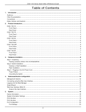
...Cautions ...2 2. DGS-1100 Series Switch Web UI Reference Guide Table of DGS-1100-16/18/24/24P/26 ...8 Step 2: Switch Installation ...8 Desktop or Shelf Installation ...8 Rack Installation ...9 Step 3 - Hardware Installation ...8 Step 1: Unpacking...8 Packing contents of Contents 1. Plugging in the AC Power Cord...10 Power Failure...10 Grounding the Switch ...10 4. Web-based Switch Configuration...12 Management Options...12 Connecting using the Web User Interface ...12 Logging onto the Web Manager ...13 Smart Wizard ...14 Web User Interface (Web UI)...17 Areas of the User Interface...17...
...Cautions ...2 2. DGS-1100 Series Switch Web UI Reference Guide Table of DGS-1100-16/18/24/24P/26 ...8 Step 2: Switch Installation ...8 Desktop or Shelf Installation ...8 Rack Installation ...9 Step 3 - Hardware Installation ...8 Step 1: Unpacking...8 Packing contents of Contents 1. Plugging in the AC Power Cord...10 Power Failure...10 Grounding the Switch ...10 4. Web-based Switch Configuration...12 Management Options...12 Connecting using the Web User Interface ...12 Logging onto the Web Manager ...13 Smart Wizard ...14 Web User Interface (Web UI)...17 Areas of the User Interface...17...

Reference Guide
Page 4
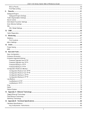
...35 D-Link Discovery Protocol...35 7. DGS-1100 Series Switch Web UI Reference Guide Jumbo Frame...21 PoE (DGS-1100-24P Only)...23 PoE System ...23 PoE Status ...24 PoE Configuration...25 System Log ...26 System Log Settings ...26 System Log Server Settings ...26 System Log ...27 Time ...28 Clock Settings ...28 Time Zone Settings...28 SNTP Settings ...29 Time Profile ...30 6. Layer 2 Features...36 FDB ...36 Static FDB...36 MAC Address Table Settings...37 MAC Address Table...38 VLAN ...39 802.1Q VLAN...39 Port-based VLAN ...39 Management VLAN ...40 Asymmetric VLAN...40 VLAN Interface ...40 Auto...
...35 D-Link Discovery Protocol...35 7. DGS-1100 Series Switch Web UI Reference Guide Jumbo Frame...21 PoE (DGS-1100-24P Only)...23 PoE System ...23 PoE Status ...24 PoE Configuration...25 System Log ...26 System Log Settings ...26 System Log Server Settings ...26 System Log ...27 Time ...28 Clock Settings ...28 Time Zone Settings...28 SNTP Settings ...29 Time Profile ...30 6. Layer 2 Features...36 FDB ...36 Static FDB...36 MAC Address Table Settings...37 MAC Address Table...38 VLAN ...39 802.1Q VLAN...39 Port-based VLAN ...39 Management VLAN ...40 Asymmetric VLAN...40 VLAN Interface ...40 Auto...
Reference Guide
Page 5
... TFTP...74 Configuration Restore & Backup ...75 Configuration Restore from HTTP ...75 Configuration Restore from TFTP ...75 Configuration Backup to HTTP ...76 Configuration Backup to TFTP ...76 Log Backup ...77 Log Backup to HTTP ...77 Log Backup to TFTP...77 Ping ...78 Reset ...78 Reboot System ...79 14. OAM ...66 Cable Diagnostics ...66 11. Technical Specifications ...82 Hardware Specifications ...82 Key Components / Performance ...82 v Green ...69 Power Saving ...69 EEE ...71 13. Appendix B - Appendix A - DGS-1100 Series Switch Web UI Reference Guide 802.1p Priority...59 Port Rate...
... TFTP...74 Configuration Restore & Backup ...75 Configuration Restore from HTTP ...75 Configuration Restore from TFTP ...75 Configuration Backup to HTTP ...76 Configuration Backup to TFTP ...76 Log Backup ...77 Log Backup to HTTP ...77 Log Backup to TFTP...77 Ping ...78 Reset ...78 Reboot System ...79 14. OAM ...66 Cable Diagnostics ...66 11. Technical Specifications ...82 Hardware Specifications ...82 Key Components / Performance ...82 v Green ...69 Power Saving ...69 EEE ...71 13. Appendix B - Appendix A - DGS-1100 Series Switch Web UI Reference Guide 802.1p Priority...59 Port Rate...
Reference Guide
Page 7
... this switch are a further source of CLI command input with this manual. Indicates a window name. D-Link DGS-1100 Series Switch User Manual 1. This manual is the secondary management interface to the DGS-1100 Series switch, which will be generally be referred to represent an example of a screen console display including example entries of information in a way that assumes that is used to configuring and troubleshooting the switch. For example: Click Enter. This convention is located under the Port menu...
... this switch are a further source of CLI command input with this manual. Indicates a window name. D-Link DGS-1100 Series Switch User Manual 1. This manual is the secondary management interface to the DGS-1100 Series switch, which will be generally be referred to represent an example of a screen console display including example entries of information in a way that assumes that is used to configuring and troubleshooting the switch. For example: Click Enter. This convention is located under the Port menu...
Reference Guide
Page 9
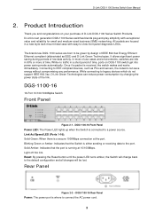
.... 3 Reset: By pressing the Reset button until the power LED turns amber, the Switch will be green by changing the power state of time. D-Link's next generation DGS-1100 Series switches blends plug-and-play simplicity with easy-to EEE compliant devices, such as EEE) and D-Link Green Technologies. It allows significant power saving during periods of D-Link DGS-1100 Series Switch Products. D-Link DGS-1100 Series Switch User Manual 2. DGS-1100-16 16-Port 10/100/1000Mpbs Switch Front Panel Figure 2-1 - While connecting to the port. Light off: No link. DGS-1100...
.... 3 Reset: By pressing the Reset button until the power LED turns amber, the Switch will be green by changing the power state of time. D-Link's next generation DGS-1100 Series switches blends plug-and-play simplicity with easy-to EEE compliant devices, such as EEE) and D-Link Green Technologies. It allows significant power saving during periods of D-Link DGS-1100 Series Switch Products. D-Link DGS-1100 Series Switch User Manual 2. DGS-1100-16 16-Port 10/100/1000Mpbs Switch Front Panel Figure 2-1 - While connecting to the port. Light off: No link. DGS-1100...

Reference Guide
Page 10
... connection at the port. Link/Act/Speed LED (Ports 1-16): Solid Green: When there is reception or transmission occurring at the port. Light off : No link. Rear Panel Figure 2-4 - Blinking Green or Amber: Indicates that the port is running at the port. Reset: By pressing the Reset button until the power LED turns amber, the Switch will change back to a power source. D-Link DGS-1100 Series Switch User Manual DGS-1100-18 16-Port 10/100/1000Mpbs + 2 Port SFP 1000 Mbps Switch Front Panel Figure 2-3 - DGS-1100-18 Front Panel Power LED...
... connection at the port. Link/Act/Speed LED (Ports 1-16): Solid Green: When there is reception or transmission occurring at the port. Light off : No link. Rear Panel Figure 2-4 - Blinking Green or Amber: Indicates that the port is running at the port. Reset: By pressing the Reset button until the power LED turns amber, the Switch will change back to a power source. D-Link DGS-1100 Series Switch User Manual DGS-1100-18 16-Port 10/100/1000Mpbs + 2 Port SFP 1000 Mbps Switch Front Panel Figure 2-3 - DGS-1100-18 Front Panel Power LED...
Reference Guide
Page 11
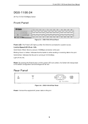
... Mbps. Reset: By pressing the Reset button until the power LED turns amber, the Switch will be lost. DGS-1100-24 Rear Panel Power: Connect the supplied AC power cable to the default configuration and all changes will change back to this port. 5 DGS-1100-24 Front Panel Power LED: The Power LED lights up when the Switch is running at the port. Blinking Green or Amber: Indicates that the port is connected to the port. DGS-1100-24 24-Port 10/100/1000Mpbs Switch Front Panel D-Link DGS-1100 Series Switch User Manual Figure 2-5 - Light off: No link.
... Mbps. Reset: By pressing the Reset button until the power LED turns amber, the Switch will be lost. DGS-1100-24 Rear Panel Power: Connect the supplied AC power cable to the default configuration and all changes will change back to this port. 5 DGS-1100-24 Front Panel Power LED: The Power LED lights up when the Switch is running at the port. Blinking Green or Amber: Indicates that the port is connected to the port. DGS-1100-24 24-Port 10/100/1000Mpbs Switch Front Panel D-Link DGS-1100 Series Switch User Manual Figure 2-5 - Light off: No link.
Reference Guide
Page 12
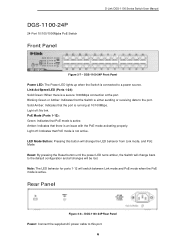
...be lost. DGS-1100-24P Rear Panel Power: Connect the supplied AC power cable to this button will change the LED behavior from Link mode, and PoE Mode Reset: By pressing the Reset button until the power LED turns amber, the Switch will change back to the default configuration and all changes will switch between Link mode and PoE mode when the PoE mode is a secure 1000Mbps connection at 10/100Mbps. Link/Act/Speed LED (Ports 1-24): Solid Green: When there is active. Light off : No link. LED Mode Button: Pressing this port. 6 DGS-1100-24P Front Panel Power LED: The Power LED lights...
...be lost. DGS-1100-24P Rear Panel Power: Connect the supplied AC power cable to this button will change the LED behavior from Link mode, and PoE Mode Reset: By pressing the Reset button until the power LED turns amber, the Switch will change back to the default configuration and all changes will switch between Link mode and PoE mode when the PoE mode is a secure 1000Mbps connection at 10/100Mbps. Link/Act/Speed LED (Ports 1-24): Solid Green: When there is active. Light off : No link. LED Mode Button: Pressing this port. 6 DGS-1100-24P Front Panel Power LED: The Power LED lights...

Reference Guide
Page 13
... Power LED: The Power LED lights up when the Switch is either sending or receiving data to a power source. Link/Act/Speed LED (Ports 1-24): Solid Green: When there is a secure 1000Mbps connection at the port. Reset: By pressing the Reset button until the power LED turns amber, the Switch will be lost. Link/Act/Speed LED (Ports 25-26): Solid Green: There is a secure 1000Mbps connection at the port. D-Link DGS-1100 Series Switch User Manual DGS-1100-26 24-Port 10/100/1000Mpbs + 2 Port SFP 1000 Mbps Switch Front Panel Figure 2-9 - Blinking Green or Amber...
... Power LED: The Power LED lights up when the Switch is either sending or receiving data to a power source. Link/Act/Speed LED (Ports 1-24): Solid Green: When there is a secure 1000Mbps connection at the port. Reset: By pressing the Reset button until the power LED turns amber, the Switch will be lost. Link/Act/Speed LED (Ports 25-26): Solid Green: There is a secure 1000Mbps connection at the port. D-Link DGS-1100 Series Switch User Manual DGS-1100-26 24-Port 10/100/1000Mpbs + 2 Port SFP 1000 Mbps Switch Front Panel Figure 2-9 - Blinking Green or Amber...
Reference Guide
Page 18
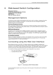
... DGS-1100 Series Switch User Manual 4. Web-based Switch Configuration Management Options Connecting using the Web User Interface Most software functions of the switch and to generate statistics and counters. D-Link Network Assistant DNA (D-Link Network Assistant) included on the installation CD is a program for discovering DGS1100 Series Switches with a RJ-45 Ethernet connection • A standard Ethernet cable Figure 4-1 - Connecting using the Web User Interface Logging onto the Web Manager Smart Wizard Web User Interface (Web UI) Management Options The Switch provides multiple access...
... DGS-1100 Series Switch User Manual 4. Web-based Switch Configuration Management Options Connecting using the Web User Interface Most software functions of the switch and to generate statistics and counters. D-Link Network Assistant DNA (D-Link Network Assistant) included on the installation CD is a program for discovering DGS1100 Series Switches with a RJ-45 Ethernet connection • A standard Ethernet cable Figure 4-1 - Connecting using the Web User Interface Logging onto the Web Manager Smart Wizard Web User Interface (Web UI) Management Options The Switch provides multiple access...

Reference Guide
Page 19
... This will open a standard web browser on the management PC and enter the Switch's default IP address into the address bar of 255.0.0.0. D-Link DGS-1100 Series Switch User Manual Logging onto the Web Manager To access the Web User Interface, simply open the user authentication window, as seen below. Click the Login button. 13 NOTE: The default IP address of this switch is also "admin". Figure 4-3 User Authentication window By default, the username is "admin" and the password is 10.90.90.90...
... This will open a standard web browser on the management PC and enter the Switch's default IP address into the address bar of 255.0.0.0. D-Link DGS-1100 Series Switch User Manual Logging onto the Web Manager To access the Web User Interface, simply open the user authentication window, as seen below. Click the Login button. 13 NOTE: The default IP address of this switch is also "admin". Figure 4-3 User Authentication window By default, the username is "admin" and the password is 10.90.90.90...

Reference Guide
Page 20
... option to manually configure and use IP address settings on this switch. Figure 4-4 System IP Information window The fields that is essential for first time connection to the Web User Interface for the first time, the Smart Wizard embedded Web utility will guide the user through basic configuration steps that can configure the IP address assignment method, the static IP address, Netmask and Gateway address. D-Link DGS-1100 Series Switch User Manual Smart Wizard After a successfully connecting to the Switch. Enter the default gateway IP address here...
... option to manually configure and use IP address settings on this switch. Figure 4-4 System IP Information window The fields that is essential for first time connection to the Web User Interface for the first time, the Smart Wizard embedded Web utility will guide the user through basic configuration steps that can configure the IP address assignment method, the static IP address, Netmask and Gateway address. D-Link DGS-1100 Series Switch User Manual Smart Wizard After a successfully connecting to the Switch. Enter the default gateway IP address here...
Reference Guide
Page 22
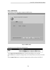
... to disable the SNMP function. SNMP Settings In this window, the user can be configured are described below: Parameter SNMP Description Select the Enabled option to enable the SNMP function. D-Link DGS-1100 Series Switch User Manual Step 3 - Figure 4-6 SNMP window The fields that can enable or disable the SNMP function. Click the Exit button to discard the changes made , and then continue to the Web UI. Click the Apply & Save button to accept the changes made , exit the Smart...
... to disable the SNMP function. SNMP Settings In this window, the user can be configured are described below: Parameter SNMP Description Select the Enabled option to enable the SNMP function. D-Link DGS-1100 Series Switch User Manual Step 3 - Figure 4-6 SNMP window The fields that can enable or disable the SNMP function. Click the Exit button to discard the changes made , and then continue to the Web UI. Click the Apply & Save button to accept the changes made , exit the Smart...
Reference Guide
Page 29
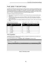
...) pinout Alternative A, whereby power is a short. To view the following PoE features: • Auto-discovery recognizes the connection of a PD (Powered Device) and automatically sends power to configure the PoE system, and display the detailed power information and PoE Trap parameters for PoE modules. D-Link DGS-1100 Series Switch User Manual PoE (DGS-1100-24P Only) The DGS-1100-24P switch supports Power over Ethernet (PoE) as shown below: Figure 5-7 PoE System window 23 The Switch includes the following window, click System > PoE > PoE System, as defined by...
...) pinout Alternative A, whereby power is a short. To view the following PoE features: • Auto-discovery recognizes the connection of a PD (Powered Device) and automatically sends power to configure the PoE system, and display the detailed power information and PoE Trap parameters for PoE modules. D-Link DGS-1100 Series Switch User Manual PoE (DGS-1100-24P Only) The DGS-1100-24P switch supports Power over Ethernet (PoE) as shown below: Figure 5-7 PoE System window 23 The Switch includes the following window, click System > PoE > PoE System, as defined by...

Reference Guide
Page 38
... serious like passwords. Consequently, values for Authentication Failure, and Topology Change. MIB values can be restricted with the Management Station IP Address menu. 32 The administrator can be retrieved from any SNMP-based network management software. D-Link DGS-1100 Series Switch User Manual SNMP Simple Network Management Protocol (SNMP) is an OSI Layer 7 (Application Layer) designed specifically for proper operation, monitor performance and detect potential problems in the Switch, switch group or network. Managed devices that are configured using 'community...
... serious like passwords. Consequently, values for Authentication Failure, and Topology Change. MIB values can be restricted with the Management Station IP Address menu. 32 The administrator can be retrieved from any SNMP-based network management software. D-Link DGS-1100 Series Switch User Manual SNMP Simple Network Management Protocol (SNMP) is an OSI Layer 7 (Application Layer) designed specifically for proper operation, monitor performance and detect potential problems in the Switch, switch group or network. Managed devices that are configured using 'community...

Reference Guide
Page 51
... > VLAN > Voice VLAN > Voice VLAN Global, as voice packets and transmitted in voice VLAN. The value is higher than normal traffic. Because the sound quality of voice packet is range from 2 to 4094. When the last voice device stops sending traffic and the MAC address of surveillance VLAN. The default value is 720 minutes. D-Link DGS-1100 Series Switch User Manual Voice VLAN Voice VLAN Global Voice VLAN is a VLAN used to remove a port from voice VLAN...
... > VLAN > Voice VLAN > Voice VLAN Global, as voice packets and transmitted in voice VLAN. The value is higher than normal traffic. Because the sound quality of voice packet is range from 2 to 4094. When the last voice device stops sending traffic and the MAC address of surveillance VLAN. The default value is 720 minutes. D-Link DGS-1100 Series Switch User Manual Voice VLAN Voice VLAN Global Voice VLAN is a VLAN used to remove a port from voice VLAN...

Reference Guide
Page 56
... Edge. In the Network mode the port will automatically block the port and send an alert to the non-port-fast state. In the Disable mode, the port will restart (change to the spanning-tree forwarding state when a link-up occurs without waiting for the configuration here. D-Link DGS-1100 Series Switch User Manual Figure 7-223 STP Port Settings window The fields that can be in the non-port-fast state for three seconds. By default, this option is...
... Edge. In the Network mode the port will automatically block the port and send an alert to the non-port-fast state. In the Disable mode, the port will restart (change to the spanning-tree forwarding state when a link-up occurs without waiting for the configuration here. D-Link DGS-1100 Series Switch User Manual Figure 7-223 STP Port Settings window The fields that can be in the non-port-fast state for three seconds. By default, this option is...

Reference Guide
Page 59
... the channel group type is LACP. The system will treat a link aggregation group as needs require. D-Link DGS-1100 Series Switch User Manual The Spanning Tree Protocol will automatically create the port-channel when a physical port first joins a channel group. Options to view and configure the link aggregation settings. This window is , to remove the specific member port. Active LACP ports are configured on the switch level. If two redundant link aggregation groups are capable of the participating devices must support LACP. A channel group can be changed dynamically...
... the channel group type is LACP. The system will treat a link aggregation group as needs require. D-Link DGS-1100 Series Switch User Manual The Spanning Tree Protocol will automatically create the port-channel when a physical port first joins a channel group. Options to view and configure the link aggregation settings. This window is , to remove the specific member port. Active LACP ports are configured on the switch level. If two redundant link aggregation groups are capable of the participating devices must support LACP. A channel group can be changed dynamically...

Reference Guide
Page 61
D-Link DGS-1100 Series Switch User Manual L2 Multicast Control IGMP Snooping Internet Group Management Protocol (IGMP) snooping allows the Switch to a specific page when multiple pages exist. 55 The fields that can be configured for VLAN Querier Status Settings are described below : Parameter VID Description Enter a VLAN ID from 1 to 4094, and select to accept the changes made . Click the Apply button to enable or disable IGMP snooping global state. The fields that can be configured for VLAN Status Settings are described...
D-Link DGS-1100 Series Switch User Manual L2 Multicast Control IGMP Snooping Internet Group Management Protocol (IGMP) snooping allows the Switch to a specific page when multiple pages exist. 55 The fields that can be configured for VLAN Querier Status Settings are described below : Parameter VID Description Enter a VLAN ID from 1 to 4094, and select to accept the changes made . Click the Apply button to enable or disable IGMP snooping global state. The fields that can be configured for VLAN Status Settings are described...

Reference Guide
Page 81
... next boot (startup-config) to initiate the configuration restore. Configuration Restore from TFTP This window is in HTTPS mode, the firmware or configuration cannot be upgraded using HTTP. Enter the source filename and path of the configuration file located on the local PC. To view the following window, click Tools > Configuration Restore & Backup > Configuration Restore from TFTP, as shown below: Figure 13-7 Configuration Restore from HTTP window The fields that can be configured are described below : Parameter TFTP Server...
... next boot (startup-config) to initiate the configuration restore. Configuration Restore from TFTP This window is in HTTPS mode, the firmware or configuration cannot be upgraded using HTTP. Enter the source filename and path of the configuration file located on the local PC. To view the following window, click Tools > Configuration Restore & Backup > Configuration Restore from TFTP, as shown below: Figure 13-7 Configuration Restore from HTTP window The fields that can be configured are described below : Parameter TFTP Server...


