
Reference Guide
Page 2
... radio, en cuyo case, puede requerirse al usuario para que adopte las medidas adecuadas. Attenzione! Trademarks used in this text: D-Link and the D-Link logo are trademarks of this equipment in a residential area is likely to cause harmful interference in which case the user may be used... interference in which case the user will be required to take adequate measures. DGS-1100 Series Switch Web UI Reference Guide Information in this document is subject to change without the written permission of D-Link Corporation is strictly forbidden. Other trademarks and trade names may be required to...
... radio, en cuyo case, puede requerirse al usuario para que adopte las medidas adecuadas. Attenzione! Trademarks used in this text: D-Link and the D-Link logo are trademarks of this equipment in a residential area is likely to cause harmful interference in which case the user may be used... interference in which case the user will be required to take adequate measures. DGS-1100 Series Switch Web UI Reference Guide Information in this document is subject to change without the written permission of D-Link Corporation is strictly forbidden. Other trademarks and trade names may be required to...
Reference Guide
Page 3
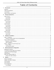
...Interface ...12 Logging onto the Web Manager ...13 Smart Wizard ...14 Web User Interface (Web UI)...17 Areas of DGS-1100-16/18/24/24P/26 ...8 Step 2: Switch Installation ...8 Desktop or Shelf Installation ...8 Rack Installation ...9 Step 3 - Introduction ...1 ... ...20 iii DGS-1100 Series Switch Web UI Reference Guide Table of Contents 1. Product Introduction...3 DGS-1100-16 ...3 Front Panel ...3 Rear Panel ...3 DGS-1100-18 ...4 Front Panel ...4 Rear Panel ...4 DGS-1100-24 ...5 Front Panel ...5 Rear Panel ...5 DGS-1100-24P ...6 Front Panel ...6 Rear Panel ...6 DGS-1100-26 ...7 Front...
...Interface ...12 Logging onto the Web Manager ...13 Smart Wizard ...14 Web User Interface (Web UI)...17 Areas of DGS-1100-16/18/24/24P/26 ...8 Step 2: Switch Installation ...8 Desktop or Shelf Installation ...8 Rack Installation ...9 Step 3 - Introduction ...1 ... ...20 iii DGS-1100 Series Switch Web UI Reference Guide Table of Contents 1. Product Introduction...3 DGS-1100-16 ...3 Front Panel ...3 Rear Panel ...3 DGS-1100-18 ...4 Front Panel ...4 Rear Panel ...4 DGS-1100-24 ...5 Front Panel ...5 Rear Panel ...5 DGS-1100-24P ...6 Front Panel ...6 Rear Panel ...6 DGS-1100-26 ...7 Front...

Reference Guide
Page 4
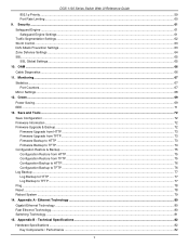
... Web UI Reference Guide Jumbo Frame...21 PoE (DGS-1100-24P Only)...23 PoE System ...23 PoE Status ...24 PoE Configuration...25 System Log ...26 System Log Settings ...26 System Log Server Settings ...26 System Log .........40 VLAN Interface ...40 Auto Surveillance VLAN ...43 Voice VLAN...45 Spanning Tree ...48 STP Global Settings ...49 STP Port Settings ...49 Loopback Detection ...50 Link Aggregation ...52 L2 Multicast Control ...55 IGMP Snooping ...55 Multicast Filtering ...57 LLDP ...58 LLDP Global Settings ...58 LLDP Neighbor Port Information ...58 8. Management ...31...
... Web UI Reference Guide Jumbo Frame...21 PoE (DGS-1100-24P Only)...23 PoE System ...23 PoE Status ...24 PoE Configuration...25 System Log ...26 System Log Settings ...26 System Log Server Settings ...26 System Log .........40 VLAN Interface ...40 Auto Surveillance VLAN ...43 Voice VLAN...45 Spanning Tree ...48 STP Global Settings ...49 STP Port Settings ...49 Loopback Detection ...50 Link Aggregation ...52 L2 Multicast Control ...55 IGMP Snooping ...55 Multicast Filtering ...57 LLDP ...58 LLDP Global Settings ...58 LLDP Neighbor Port Information ...58 8. Management ...31...
Reference Guide
Page 5
... ...79 14. Ethernet Technology ...80 Gigabit Ethernet Technology ...80 Fast Ethernet Technology...80 Switching Technology ...81 15. Appendix B - OAM ...66 Cable Diagnostics ...66 11. Appendix A - DGS-1100 Series Switch Web UI Reference Guide 802.1p Priority...59 Port Rate Limiting ...60 9.
... ...79 14. Ethernet Technology ...80 Gigabit Ethernet Technology ...80 Fast Ethernet Technology...80 Switching Technology ...81 15. Appendix B - OAM ...66 Cable Diagnostics ...66 11. Appendix A - DGS-1100 Series Switch Web UI Reference Guide 802.1p Priority...59 Port Rate Limiting ...60 9.
Reference Guide
Page 7
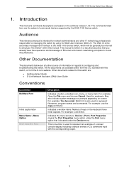
D-Link DGS-1100 Series Switch User Manual 1. The commands listed here are the...means the Port Properties menu option under the Device menu. This convention is the secondary management interface to the DGS-1100 Series switch, which will be generally be referred to simply as "the Switch" within this switch, or .... Indicates the menu structure. Used for managing the switch by the DGS-1100 Series switch. Introduction This manual's command descriptions are : • Getting started Guide • D-Link Network Assistant (DNA) User Guide Conventions Convention Boldface Font Initial capital ...
D-Link DGS-1100 Series Switch User Manual 1. The commands listed here are the...means the Port Properties menu option under the Device menu. This convention is the secondary management interface to the DGS-1100 Series switch, which will be generally be referred to simply as "the Switch" within this switch, or .... Indicates the menu structure. Used for managing the switch by the DGS-1100 Series switch. Introduction This manual's command descriptions are : • Getting started Guide • D-Link Network Assistant (DNA) User Guide Conventions Convention Boldface Font Initial capital ...
Reference Guide
Page 8
... data and tells you make better use of your switch using the information in this document, you should pay special attention to avoid the problem. D-Link DGS-1100 Series Switch User Manual Notes, Notices, and Cautions Below are examples of the three types of indicators used in this manual.
... data and tells you make better use of your switch using the information in this document, you should pay special attention to avoid the problem. D-Link DGS-1100 Series Switch User Manual Notes, Notices, and Cautions Below are examples of the three types of indicators used in this manual.
Reference Guide
Page 9
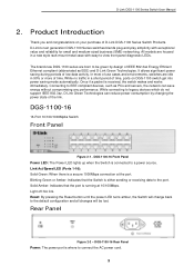
.... Connecting to be lost. Product Introduction Thank you and congratulations on DGS-1100 switch get into power saving mode automatically. While connecting to -view front panel diagnostic LEDs. DGS-1100-16 16-Port 10/100/1000Mpbs Switch Front Panel Figure 2-1 - D-Link's next generation DGS-1100 Series switches blends plug-and-play simplicity with easy-to legacy devices...
.... Connecting to be lost. Product Introduction Thank you and congratulations on DGS-1100 switch get into power saving mode automatically. While connecting to -view front panel diagnostic LEDs. DGS-1100-16 16-Port 10/100/1000Mpbs Switch Front Panel Figure 2-1 - D-Link's next generation DGS-1100 Series switches blends plug-and-play simplicity with easy-to legacy devices...

Reference Guide
Page 10
...port is connected to the port. DGS-1100-18 Front Panel Power LED: The Power LED lights up when the Switch is where to the default configuration and all changes will change back to connect the AC power cord. 4 D-Link DGS-1100 Series Switch User Manual DGS-1100-18 16-Port 10/100/1000Mpbs... + 2 Port SFP 1000 Mbps Switch Front Panel Figure 2-3 - Link/Act/Speed LED (Ports 1-16): Solid Green: When there is a secure 1000Mbps ...
...port is connected to the port. DGS-1100-18 Front Panel Power LED: The Power LED lights up when the Switch is where to the default configuration and all changes will change back to connect the AC power cord. 4 D-Link DGS-1100 Series Switch User Manual DGS-1100-18 16-Port 10/100/1000Mpbs... + 2 Port SFP 1000 Mbps Switch Front Panel Figure 2-3 - Link/Act/Speed LED (Ports 1-16): Solid Green: When there is a secure 1000Mbps ...
Reference Guide
Page 11
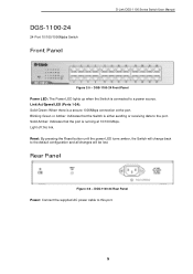
DGS-1100-24 Front Panel Power LED: The Power LED lights up when the Switch is a secure 1000Mbps connection at 10/100 Mbps. Link/Act/Speed LED (Ports 1-24): Solid Green: When there is connected to the port. Blinking Green or Amber: Indicates that the port is either sending ... LED turns amber, the Switch will change back to this port. 5 Solid Amber: Indicates that the Switch is running at the port. Light off: No link. DGS-1100-24 Rear Panel Power: Connect the supplied AC power cable to the default configuration and all changes will be lost. Rear Panel Figure...
DGS-1100-24 Front Panel Power LED: The Power LED lights up when the Switch is a secure 1000Mbps connection at 10/100 Mbps. Link/Act/Speed LED (Ports 1-24): Solid Green: When there is connected to the port. Blinking Green or Amber: Indicates that the port is either sending ... LED turns amber, the Switch will change back to this port. 5 Solid Amber: Indicates that the Switch is running at the port. Light off: No link. DGS-1100-24 Rear Panel Power: Connect the supplied AC power cable to the default configuration and all changes will be lost. Rear Panel Figure...
Reference Guide
Page 12
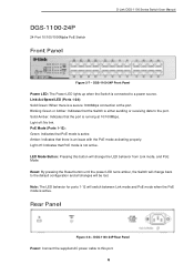
...to the port. Light off : No link. Rear Panel Figure 2-8 - LED Mode Button: Pressing this port. 6 Note: The LED behavior for ports 1-12 will be lost. DGS-1100-24P 24-Port 10/100/1000Mpbs PoE Switch Front Panel D-Link DGS-1100 Series Switch User Manual Figure 2-7 - Blinking... Green or Amber: Indicates that PoE mode is active. DGS-1100-24P Rear Panel Power: Connect the supplied AC power cable to a power source. DGS-1100-24P Front Panel ...
...to the port. Light off : No link. Rear Panel Figure 2-8 - LED Mode Button: Pressing this port. 6 Note: The LED behavior for ports 1-12 will be lost. DGS-1100-24P 24-Port 10/100/1000Mpbs PoE Switch Front Panel D-Link DGS-1100 Series Switch User Manual Figure 2-7 - Blinking... Green or Amber: Indicates that PoE mode is active. DGS-1100-24P Rear Panel Power: Connect the supplied AC power cable to a power source. DGS-1100-24P Front Panel ...

Reference Guide
Page 13
... Indicates that the Switch is a secure 1000Mbps connection at 10/100Mbps. DGS-1100-26 Rear Panel Power: Connect the supplied AC power cable to the default configuration and all changes will be lost. Light off : No link. Link/Act/Speed LED (Ports 1-24): Solid Green: When there is either... Power LED: The Power LED lights up when the Switch is reception or transmission occurring at the port. Light off : No link. D-Link DGS-1100 Series Switch User Manual DGS-1100-26 24-Port 10/100/1000Mpbs + 2 Port SFP 1000 Mbps Switch Front Panel Figure 2-9 - Blinking Green: There is connected...
... Indicates that the Switch is a secure 1000Mbps connection at 10/100Mbps. DGS-1100-26 Rear Panel Power: Connect the supplied AC power cable to the default configuration and all changes will be lost. Light off : No link. Link/Act/Speed LED (Ports 1-24): Solid Green: When there is either... Power LED: The Power LED lights up when the Switch is reception or transmission occurring at the port. Light off : No link. D-Link DGS-1100 Series Switch User Manual DGS-1100-26 24-Port 10/100/1000Mpbs + 2 Port SFP 1000 Mbps Switch Front Panel Figure 2-9 - Blinking Green: There is connected...

Reference Guide
Page 14
... the device and the objects around the switch. • Do not place heavy objects on the bottom at each corner of DGS-1100-16/18/24/24P/26 • One D-Link DGS-1100 Series Switch • One AC power cord • Four rubber feet • Screws and two mounting brackets • One... make sure all items are present and undamaged. If any item is missing or damaged, please contact your local D-Link reseller for a ground screw • One Multi-lingual Getting Started Guide • One CD with the device must be attached on the switch. D-Link DGS-1100 Series Switch User Manual 3.
... the device and the objects around the switch. • Do not place heavy objects on the bottom at each corner of DGS-1100-16/18/24/24P/26 • One D-Link DGS-1100 Series Switch • One AC power cord • Four rubber feet • Screws and two mounting brackets • One... make sure all items are present and undamaged. If any item is missing or damaged, please contact your local D-Link reseller for a ground screw • One Multi-lingual Getting Started Guide • One CD with the device must be attached on the switch. D-Link DGS-1100 Series Switch User Manual 3.

Reference Guide
Page 15
D-Link DGS-1100 Series Switch User Manual Rack Installation The switch can be mounted in an EIA standard size 11-inch rack, which can be placed in a wiring ...
D-Link DGS-1100 Series Switch User Manual Rack Installation The switch can be mounted in an EIA standard size 11-inch rack, which can be placed in a wiring ...

Reference Guide
Page 16
... on the power supply and system, a 12 to ground. Step 3: Insert the ground screw into the ground-screw opening , as seen in the figure below. D-Link DGS-1100 Series Switch User Manual Step 3 - Required Tools and Equipment • Ground screws (included in the accessory kit): One M4 x 6 mm (metric) pan-head screw •...
... on the power supply and system, a 12 to ground. Step 3: Insert the ground screw into the ground-screw opening , as seen in the figure below. D-Link DGS-1100 Series Switch User Manual Step 3 - Required Tools and Equipment • Ground screws (included in the accessory kit): One M4 x 6 mm (metric) pan-head screw •...

Reference Guide
Page 17
D-Link DGS-1100 Series Switch User Manual Figure 3-5 - Ground cable, screw and #8 terminal lug rings 11
D-Link DGS-1100 Series Switch User Manual Figure 3-5 - Ground cable, screw and #8 terminal lug rings 11
Reference Guide
Page 18
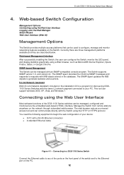
... to any of the ports on the front panel of the switch and to begin the web configuration of the DGS-1100 Series switches can be used to generate statistics and counters. D-Link DGS-1100 Series Switch User Manual 4. Currently there are three management platforms available and they are described below. The SNMP agent updates...
... to any of the ports on the front panel of the switch and to begin the web configuration of the DGS-1100 Series switches can be used to generate statistics and counters. D-Link DGS-1100 Series Switch User Manual 4. Currently there are three management platforms available and they are described below. The SNMP agent updates...

Reference Guide
Page 19
D-Link DGS-1100 Series Switch User Manual Logging onto the Web Manager To access the Web User Interface, simply open the user authentication window, as seen below. Figure 4-3 ...
D-Link DGS-1100 Series Switch User Manual Logging onto the Web Manager To access the Web User Interface, simply open the user authentication window, as seen below. Figure 4-3 ...

Reference Guide
Page 20
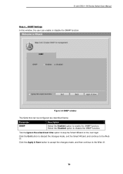
... below: Parameter Static DHCP IP Address Netmask Gateway Description Select this switch. Select the Netmask option here. Enter the default gateway IP address here. 14 D-Link DGS-1100 Series Switch User Manual Smart Wizard After a successfully connecting to the Web User Interface for first time connection to the Switch. Select this option to...
... below: Parameter Static DHCP IP Address Netmask Gateway Description Select this switch. Select the Netmask option here. Enter the default gateway IP address here. 14 D-Link DGS-1100 Series Switch User Manual Smart Wizard After a successfully connecting to the Web User Interface for first time connection to the Switch. Select this option to...

Reference Guide
Page 21
... password used with the admin account. Click the Next button to accept the changes made , exit the Smart Wizard, and continue to the Web UI. D-Link DGS-1100 Series Switch User Manual Tick the Ignore the wizard next time option to skip the Smart Wizard on the next login. Click the Exit button...
... password used with the admin account. Click the Next button to accept the changes made , exit the Smart Wizard, and continue to the Web UI. D-Link DGS-1100 Series Switch User Manual Tick the Ignore the wizard next time option to skip the Smart Wizard on the next login. Click the Exit button...
Reference Guide
Page 22
D-Link DGS-1100 Series Switch User Manual Step 3 - Click the Apply & Save button to accept the changes made , exit the Smart Wizard, and continue to the Web UI. ...
D-Link DGS-1100 Series Switch User Manual Step 3 - Click the Apply & Save button to accept the changes made , exit the Smart Wizard, and continue to the Web UI. ...
