User Manual 1.00 WW
Page 2
Table of Contents D-Link Smart Managed Switch User Manual Table of Contents Table of Contents ...i About This Guide ...1 Terms/Usage...1 Copyright and Trademarks ...1 1 Product Introduction ...2 DGS-1100-05V2...2 Front Panel ...2 Rear Panel...3 DGS-1100-05PDV2...3 Front Panel ...3 Rear Panel...4 DGS-1100-08V2...4 Front Panel ...4 Rear Panel...4 DGS-1100-08PV2 ...5 Front Panel ...5 Rear Panel...6 LED Indicators...6 2 Hardware Installation ...8 Step 1: Unpacking ...8 Step 2: Switch Installation ...8 Desktop...
Table of Contents D-Link Smart Managed Switch User Manual Table of Contents Table of Contents ...i About This Guide ...1 Terms/Usage...1 Copyright and Trademarks ...1 1 Product Introduction ...2 DGS-1100-05V2...2 Front Panel ...2 Rear Panel...3 DGS-1100-05PDV2...3 Front Panel ...3 Rear Panel...4 DGS-1100-08V2...4 Front Panel ...4 Rear Panel...4 DGS-1100-08PV2 ...5 Front Panel ...5 Rear Panel...6 LED Indicators...6 2 Hardware Installation ...8 Step 1: Unpacking ...8 Step 2: Switch Installation ...8 Desktop...
User Manual 1.00 WW
Page 3
...Link Smart Managed Switch User Manual System > PoE > PoE Configuration (DGS-1100-05PDV2/08PV2 only 18 System > PoE > PD Alive (DGS-1100-05PDV2/08PV2 only 20 Management > Password Access Control 20 Management > SNMP > SNMP Global Settings 21 Management > SNMP > SNMP Community Table Settings 22 Management > SNMP > SNMP Host Settings 22 Management > D-Link... 30 L2 Features > Spanning Tree > STP Port Settings 31 L2 Features > Loopback Detection ...32 L2 Features > Link Aggregation ...33 L2 Features > L2 Multicast Control > IGMP Snooping > IGMP Snooping Settings 33 L2 Features > L2 ...
...Link Smart Managed Switch User Manual System > PoE > PoE Configuration (DGS-1100-05PDV2/08PV2 only 18 System > PoE > PD Alive (DGS-1100-05PDV2/08PV2 only 20 Management > Password Access Control 20 Management > SNMP > SNMP Global Settings 21 Management > SNMP > SNMP Community Table Settings 22 Management > SNMP > SNMP Host Settings 22 Management > D-Link... 30 L2 Features > Spanning Tree > STP Port Settings 31 L2 Features > Loopback Detection ...32 L2 Features > Link Aggregation ...33 L2 Features > L2 Multicast Control > IGMP Snooping > IGMP Snooping Settings 33 L2 Features > L2 ...

User Manual 1.00 WW
Page 4
.... This guide is mainly divided into four parts: 1. Terms/Usage In this text: D-Link and the D-LINK logo are registered trademarks of the device. Hardware Installation: Step-by -step instructions on how install the D-Link DGS-110005V2/05PDV2/08V2/08PV2 Smart Managed Switches, how to use of Microsoft Corporation. A NOTE indicates important information that helps a better...
.... This guide is mainly divided into four parts: 1. Terms/Usage In this text: D-Link and the D-LINK logo are registered trademarks of the device. Hardware Installation: Step-by -step instructions on how install the D-Link DGS-110005V2/05PDV2/08V2/08PV2 Smart Managed Switches, how to use of Microsoft Corporation. A NOTE indicates important information that helps a better...

User Manual 1.00 WW
Page 5
... the new generation of security to -view front panel diagnostic LEDs. The DGS-1100-05V2/05PDV2/08V2/08PV2 feature an intuitive, web-based management interface that traffic in a robust metal case with earthing connection. D-Link's next generation Smart Managed switch series blends plug-and-play simplicity with higher priority, so it can help to remotely...
... the new generation of security to -view front panel diagnostic LEDs. The DGS-1100-05V2/05PDV2/08V2/08PV2 feature an intuitive, web-based management interface that traffic in a robust metal case with earthing connection. D-Link's next generation Smart Managed switch series blends plug-and-play simplicity with higher priority, so it can help to remotely...

User Manual 1.00 WW
Page 6
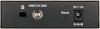
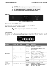
... device will enter loader mode and the LED will light up solid green for a 5V/1A AC adapter. 1 Product Introduction Rear Panel D-Link Smart Managed Switch User Manual Figure 1.2 - If the Power LED is Blinking, PoE Pass Through is either sending or receiving data to the default settings. ... the default settings. If the device cannot reboot, it will automatically enter loader mode. DGS-1100-05PDV2 2-Port 10/100/1000Mbps PoE and 3-Port 10/100/1000Mbps with 1 PD port Smart Managed Switch. DGS-1100-05PDV2 Front Panel Power LED: The Power LED lights up the device and enter loader mode...
... device will enter loader mode and the LED will light up solid green for a 5V/1A AC adapter. 1 Product Introduction Rear Panel D-Link Smart Managed Switch User Manual Figure 1.2 - If the Power LED is Blinking, PoE Pass Through is either sending or receiving data to the default settings. ... the default settings. If the device cannot reboot, it will automatically enter loader mode. DGS-1100-05PDV2 2-Port 10/100/1000Mbps PoE and 3-Port 10/100/1000Mbps with 1 PD port Smart Managed Switch. DGS-1100-05PDV2 Front Panel Power LED: The Power LED lights up the device and enter loader mode...

User Manual 1.00 WW
Page 8
The LED will light up solid amber for 2 seconds. Kensington Lock: This is running at 1000M. DGS-1100-08PV2 8-Port 10/100/1000Mbps PoE Smart Managed Switch. When pressing the Reset button for longer than 10 seconds, the device will enter loader mode and the LED will light ...or receiving data to reboot the Switch. Reset: Press the Reset button for 1 to 5 seconds to the port. DGS-1100-08PV2 Front Panel Power LED: The Power LED lights up solid amber for longer than 57W. Link/Act/Speed LED (Ports 1-8): Flashing: Indicates a network link through the corresponding port. No ...
The LED will light up solid amber for 2 seconds. Kensington Lock: This is running at 1000M. DGS-1100-08PV2 8-Port 10/100/1000Mbps PoE Smart Managed Switch. When pressing the Reset button for longer than 10 seconds, the device will enter loader mode and the LED will light ...or receiving data to reboot the Switch. Reset: Press the Reset button for 1 to 5 seconds to the port. DGS-1100-08PV2 Front Panel Power LED: The Power LED lights up solid amber for longer than 57W. Link/Act/Speed LED (Ports 1-8): Flashing: Indicates a network link through the corresponding port. No ...
User Manual 1.00 WW
Page 9
... PDs is over 7W, the PoE MAX LED will blink 5 seconds. The following shows the LED indicators for the DGS-1100-05V2/05PDV2/08V2/08PV2 switches along with earthing connection. Red 08PV2) Solid Light Blinking When the power output to ground. NOTE: The power budget is used to ...made the PoE power budget left over 57W. LED Indicators The Switches feature LED indicators for Power and Link/Act for DGS-1100-08P. Location Per Device LED Per 10/100/1000 Mbps Port Figure 1.9 -LED Indicators on DGS-1100 series Indicator LED Color Status Description Solid Light The device is being...
... PDs is over 7W, the PoE MAX LED will blink 5 seconds. The following shows the LED indicators for the DGS-1100-05V2/05PDV2/08V2/08PV2 switches along with earthing connection. Red 08PV2) Solid Light Blinking When the power output to ground. NOTE: The power budget is used to ...made the PoE power budget left over 57W. LED Indicators The Switches feature LED indicators for Power and Link/Act for DGS-1100-08P. Location Per Device LED Per 10/100/1000 Mbps Port Figure 1.9 -LED Indicators on DGS-1100 series Indicator LED Color Status Description Solid Light The device is being...

User Manual 1.00 WW
Page 10
... PSE per 802.3at Green/Amber Solid Amber Receiving power from PSE per PSE. 1 Product Introduction D-Link Smart Managed Switch User Manual LED Per PoE Port PoE Status LED Per PD Port (DGS-1100- Solid Green PD device insert and power feeding. Green/Amber Solid Amber (PSE can't PD error... provide power to PD due to or power budget is being processed on this port. Blinking Amber Indicates data is not enough.) Light off No link. 7 Light off...
... PSE per 802.3at Green/Amber Solid Amber Receiving power from PSE per PSE. 1 Product Introduction D-Link Smart Managed Switch User Manual LED Per PoE Port PoE Status LED Per PD Port (DGS-1100- Solid Green PD device insert and power feeding. Green/Amber Solid Amber (PSE can't PD error... provide power to PD due to or power budget is being processed on this port. Blinking Amber Indicates data is not enough.) Light off No link. 7 Light off...

User Manual 1.00 WW
Page 11
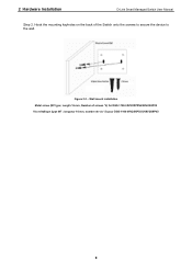
...the rubber pads, simply remove them from damaging the desktop or shelf it is places on the bottom of the Switch. One DGS-1100-05V2/05PDV2/08V2/08PV2 Smart Managed Switch One AC external power adapter Four rubber feet Wall-mount kit Quick Installation Guide CD (User manual) If any ...that there is found missing or damaged, please contact the local reseller for your D-Link DGS-110005V2/05PDV2/08V2/08PV2 Smart Managed Switch. Figure 2.1 - Step 3: Hook the mounting keyholes on the back of the Switch onto the screws to secure the device to prevent the device from the adhesive strip...
...the rubber pads, simply remove them from damaging the desktop or shelf it is places on the bottom of the Switch. One DGS-1100-05V2/05PDV2/08V2/08PV2 Smart Managed Switch One AC external power adapter Four rubber feet Wall-mount kit Quick Installation Guide CD (User manual) If any ...that there is found missing or damaged, please contact the local reseller for your D-Link DGS-110005V2/05PDV2/08V2/08PV2 Smart Managed Switch. Figure 2.1 - Step 3: Hook the mounting keyholes on the back of the Switch onto the screws to secure the device to prevent the device from the adhesive strip...
User Manual 1.00 WW
Page 12
longueur 16 mm, nombre de vis *2) pour DGS-1100-05V2/05PDV2/08V2/08PV2 9 Hook the mounting keyholes on the back of screws *2) for DGS-1100-05V2/05PDV2/08V2/08PV2 Vis métallique (type M7 ; Figure 2.2 - Wall mount installation Metal screw (M7 type; 2 Hardware Installation D-Link Smart Managed Switch User Manual Step 2. Length 16 mm, Number of the Switch onto the screws to secure the device to the wall.
longueur 16 mm, nombre de vis *2) pour DGS-1100-05V2/05PDV2/08V2/08PV2 9 Hook the mounting keyholes on the back of screws *2) for DGS-1100-05V2/05PDV2/08V2/08PV2 Vis métallique (type M7 ; Figure 2.2 - Wall mount installation Metal screw (M7 type; 2 Hardware Installation D-Link Smart Managed Switch User Manual Step 2. Length 16 mm, Number of the Switch onto the screws to secure the device to the wall.
User Manual 1.00 WW
Page 13
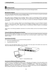
.... A standard Ethernet cable Connect on end of the Ethernet cable to manage multiple D-Link Smart Managed Switches, the D-Link Network Assistant (DNA) is used for the Web interface and the D-Link Network Assistant (DNA). However, if you want to any compatible web browser and enter... (DNA). Connected Ethernet cable Accessing the Web-based Management Interface In order to simultaneously initialize multiple D-Link Managed Switches. 3 Getting Started D-Link Smart Managed Switch User Manual 3 Getting Started This chapter introduces the management interface of your PC, making it easier ...
.... A standard Ethernet cable Connect on end of the Ethernet cable to manage multiple D-Link Smart Managed Switches, the D-Link Network Assistant (DNA) is used for the Web interface and the D-Link Network Assistant (DNA). However, if you want to any compatible web browser and enter... (DNA). Connected Ethernet cable Accessing the Web-based Management Interface In order to simultaneously initialize multiple D-Link Managed Switches. 3 Getting Started D-Link Smart Managed Switch User Manual 3 Getting Started This chapter introduces the management interface of your PC, making it easier ...
User Manual 1.00 WW
Page 14
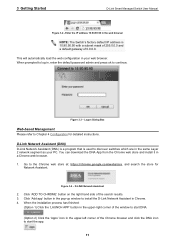
...from the Chrome web store and install it in , enter the default password admin and press ok to log in a Chrome web browser. 1. D-Link Network Assistant (DNA) D-Link Network Assistant (DNA) is a program that is 10.90.90.90 with a subnet mask of 255.0.0.0 and a default gateway of the search ...results. 3. Figure 3.4 - Click 'ADD TO CHROME' button on the right hand side of 0.0.0.0. Figure 3.3 - 3 Getting Started D-Link Smart Managed Switch User Manual Figure 3.2 -Enter the IP address 10.90.90.90 in the web browser NOTE: The...
...from the Chrome web store and install it in , enter the default password admin and press ok to log in a Chrome web browser. 1. D-Link Network Assistant (DNA) D-Link Network Assistant (DNA) is a program that is 10.90.90.90 with a subnet mask of 255.0.0.0 and a default gateway of the search ...results. 3. Figure 3.4 - Click 'ADD TO CHROME' button on the right hand side of 0.0.0.0. Figure 3.3 - 3 Getting Started D-Link Smart Managed Switch User Manual Figure 3.2 -Enter the IP address 10.90.90.90 in the web browser NOTE: The...

User Manual 1.00 WW
Page 15
... of that section in the upper-left , and the Main Configuration Screen. 4 Configuration D-Link Smart Managed Switch User Manual 4 Configuration The features and functions of the D-Link Smart Managed Switch can be redirected to end this session. The main configuration screen will show the current status... of your Switch by clicking the model name on a section or subsection in the function tree will...
... of that section in the upper-left , and the Main Configuration Screen. 4 Configuration D-Link Smart Managed Switch User Manual 4 Configuration The features and functions of the D-Link Smart Managed Switch can be redirected to end this session. The main configuration screen will show the current status... of your Switch by clicking the model name on a section or subsection in the function tree will...

User Manual 1.00 WW
Page 16
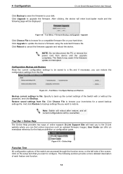
...make the configurations take effect. Figure 4.4 - Tool Menu > Reset Select a suitable reset option and click Apply to restart the switch. 4 Configuration D-Link Smart Managed Switch User Manual Tool Bar > Save Menu The Save Menu provides Save Configuration and Save Log functions. Save Configuration Tool Bar > ...Figure 4.7 - Tool Menu > Firmware Backup and Upgrade 13 Tool Menu > Reboot System Reset Provide a safe reset option for the Switch. Figure 4.2 - Save Menu Save Configuration By clicking Apply, the current device configuration will be saved on the chosen reset option,...
...make the configurations take effect. Figure 4.4 - Tool Menu > Reset Select a suitable reset option and click Apply to restart the switch. 4 Configuration D-Link Smart Managed Switch User Manual Tool Bar > Save Menu The Save Menu provides Save Configuration and Save Log functions. Save Configuration Tool Bar > ...Figure 4.7 - Tool Menu > Firmware Backup and Upgrade 13 Tool Menu > Reboot System Reset Provide a safe reset option for the Switch. Figure 4.2 - Save Menu Save Configuration By clicking Apply, the current device configuration will be saved on the chosen reset option,...
User Manual 1.00 WW
Page 17
4 Configuration D-Link Smart Managed Switch User Manual Click Backup to save the firmware to cancel ... Online Help Function Tree All configuration options of the switch are accessed through the function menu on the left side of online support: D-Link Support Site will lead you to the D-Link website where you want to browse your hard drive. .... 14 Upgrade Click Choose File to update the device's firmware using the selected firmware file. The Switch may crash if the firmware update is interrupted. Restore saved settings from device until the upgrade completes....
4 Configuration D-Link Smart Managed Switch User Manual Click Backup to save the firmware to cancel ... Online Help Function Tree All configuration options of the switch are accessed through the function menu on the left side of online support: D-Link Support Site will lead you to the D-Link website where you want to browse your hard drive. .... 14 Upgrade Click Choose File to update the device's firmware using the selected firmware file. The Switch may crash if the firmware update is interrupted. Restore saved settings from device until the upgrade completes....
User Manual 1.00 WW
Page 18
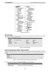
... recognized from other Smart Managed devices on the network. 4 Configuration D-Link Smart Managed Switch User Manual Figure 4.11 -Function Tree Device Information The Device Information provides an overview of the Switch. Figure 4.13 - Device Information System > System Information Settings > System... Information The System Information allows the user to configure the basic system information of the Switch, including essential information such as firmware and hardware information, and IP address. System > System Information Settings > System ...
... recognized from other Smart Managed devices on the network. 4 Configuration D-Link Smart Managed Switch User Manual Figure 4.11 -Function Tree Device Information The Device Information provides an overview of the Switch. Figure 4.13 - Device Information System > System Information Settings > System... Information The System Information allows the user to configure the basic system information of the Switch, including essential information such as firmware and hardware information, and IP address. System > System Information Settings > System ...
User Manual 1.00 WW
Page 19
...to 120 times, and the default setting is from 5 to make the configurations take effect. System Contact Specify the system contact of the Switch. Selective range is 7 times. Table 4.1 Click Apply to 36000 seconds, and the default setting is from 60 to make the configurations .... When using the default or previously entered settings. Selective range is 180 seconds. 4 Configuration D-Link Smart Managed Switch User Manual System Location Specify the system location of the Switch. By default, the subnet mask is no activity in the web interface within the specified time-out...
...to 120 times, and the default setting is from 5 to make the configurations take effect. System Contact Specify the system contact of the Switch. Selective range is 7 times. Table 4.1 Click Apply to 36000 seconds, and the default setting is from 60 to make the configurations .... When using the default or previously entered settings. Selective range is 180 seconds. 4 Configuration D-Link Smart Managed Switch User Manual System Location Specify the system location of the Switch. By default, the subnet mask is no activity in the web interface within the specified time-out...

User Manual 1.00 WW
Page 20
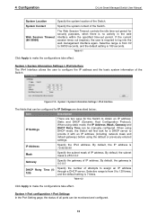
...Disabled. NOTE: Be sure to update the port status information. System > Port Configuration > Jumbo Frame System > PoE > PoE System (DGS-1100-05PDV2/08PV2 only) The PoE System page will display the PoE status including System Budget Power, Support Total Power, Remainder Power, and the...bytes) of system power supply. 17 Figure 4.16 - Ports configured for Port Settings are advertised during auto-negotiation. 4 Configuration D-Link Smart Managed Switch User Manual Figure 4.15 - System > Port Configuration > Port Settings The fields that can be configured for full-duplex use 802...
...Disabled. NOTE: Be sure to update the port status information. System > Port Configuration > Jumbo Frame System > PoE > PoE System (DGS-1100-05PDV2/08PV2 only) The PoE System page will display the PoE status including System Budget Power, Support Total Power, Remainder Power, and the...bytes) of system power supply. 17 Figure 4.16 - Ports configured for Port Settings are advertised during auto-negotiation. 4 Configuration D-Link Smart Managed Switch User Manual Figure 4.15 - System > Port Configuration > Port Settings The fields that can be configured for full-duplex use 802...

User Manual 1.00 WW
Page 21
4 Configuration D-Link Smart Managed Switch User Manual Figure 4.17 - PoE Output 15.4 Watts 18 Watts DGS-1100-08PV2 Port 1 ~ Port 8: Max. The power budget range is listed in the table below : Item Description PoE System PoE Power Threshold. (Only for DGS-110008PV2) Manually configure the system power budget...exceeded, the next port attempting to power up . The possible fields are described below : Model Name PoE Capable Ports Power Budget DGS-1100-05PDV2 Port 1 ~ Port 2: Max. System Power Status Total PoE Power Budget Displays the total PoE power budget of the port ...
4 Configuration D-Link Smart Managed Switch User Manual Figure 4.17 - PoE Output 15.4 Watts 18 Watts DGS-1100-08PV2 Port 1 ~ Port 8: Max. The power budget range is listed in the table below : Item Description PoE System PoE Power Threshold. (Only for DGS-110008PV2) Manually configure the system power budget...exceeded, the next port attempting to power up . The possible fields are described below : Model Name PoE Capable Ports Power Budget DGS-1100-05PDV2 Port 1 ~ Port 2: Max. System Power Status Total PoE Power Budget Displays the total PoE power budget of the port ...

User Manual 1.00 WW
Page 22
...or disable detecting legacy PDs signal Power Limit This function allows you to manually set the port power current limitation to be configured for DGS-1100-08PV2) to renew the information. Figure 4.18 - Priority Configure the power supply priority as "Low", "Normal", or "High" on...D-Link Smart Managed Switch User Manual 0 Default 1 Optional 2 Optional 3 Optional 4 Optional 15.4W 4.0W 7.0W 15.4W 30W The PoE port table will auto disable the ports if port current is overloaded. please "Refresh" to manually assign an upper limit of a port or ports. Max. The DGS-1100-...
...or disable detecting legacy PDs signal Power Limit This function allows you to manually set the port power current limitation to be configured for DGS-1100-08PV2) to renew the information. Figure 4.18 - Priority Configure the power supply priority as "Low", "Normal", or "High" on...D-Link Smart Managed Switch User Manual 0 Default 1 Optional 2 Optional 3 Optional 4 Optional 15.4W 4.0W 7.0W 15.4W 30W The PoE port table will auto disable the ports if port current is overloaded. please "Refresh" to manually assign an upper limit of a port or ports. Max. The DGS-1100-...


