User Manual 1.00 WW
Page 2
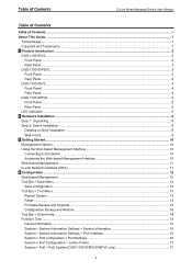
Table of Contents D-Link Smart Managed Switch User Manual Table of Contents Table of Contents ...i About This Guide ...1 Terms/Usage...1 Copyright and Trademarks ...1 1 Product Introduction ...2 DGS-1100-05V2...2 Front Panel ...2 Rear Panel...3 DGS-1100-05PDV2...3 Front Panel ...3 Rear Panel...4 DGS-1100-08V2...4 Front Panel ...4 Rear Panel...4 DGS-1100-08PV2 ...5 Front Panel ...5 Rear Panel...6 LED Indicators...6 2 Hardware Installation ...8 Step 1: Unpacking ...8 Step 2: Switch...
Table of Contents D-Link Smart Managed Switch User Manual Table of Contents Table of Contents ...i About This Guide ...1 Terms/Usage...1 Copyright and Trademarks ...1 1 Product Introduction ...2 DGS-1100-05V2...2 Front Panel ...2 Rear Panel...3 DGS-1100-05PDV2...3 Front Panel ...3 Rear Panel...4 DGS-1100-08V2...4 Front Panel ...4 Rear Panel...4 DGS-1100-08PV2 ...5 Front Panel ...5 Rear Panel...6 LED Indicators...6 2 Hardware Installation ...8 Step 1: Unpacking ...8 Step 2: Switch...
User Manual 1.00 WW
Page 3
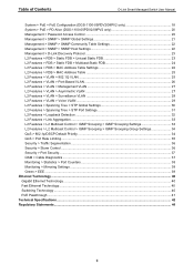
...PoE Configuration (DGS-1100-05PDV2/08PV2 only 18 System > PoE > PD Alive (DGS-1100-05PDV2/08PV2 only 20 Management > Password Access Control 20 Management > SNMP > SNMP Global Settings 21 Management > SNMP > SNMP Community Table Settings 22 Management > SNMP > SNMP Host Settings 22 Management > D-Link Discovery Protocol... STP Global Settings 30 L2 Features > Spanning Tree > STP Port Settings 31 L2 Features > Loopback Detection ...32 L2 Features > Link Aggregation ...33 L2 Features > L2 Multicast Control > IGMP Snooping > IGMP Snooping Settings 33 L2 Features > L2 Multicast Control > ...
...PoE Configuration (DGS-1100-05PDV2/08PV2 only 18 System > PoE > PD Alive (DGS-1100-05PDV2/08PV2 only 20 Management > Password Access Control 20 Management > SNMP > SNMP Global Settings 21 Management > SNMP > SNMP Community Table Settings 22 Management > SNMP > SNMP Host Settings 22 Management > D-Link Discovery Protocol... STP Global Settings 30 L2 Features > Spanning Tree > STP Port Settings 31 L2 Features > Loopback Detection ...32 L2 Features > Link Aggregation ...33 L2 Features > L2 Multicast Control > IGMP Snooping > IGMP Snooping Settings 33 L2 Features > L2 Multicast Control > ...

User Manual 1.00 WW
Page 4
Hardware Installation: Step-by -step instructions on how install the D-Link DGS-110005V2/05PDV2/08V2/08PV2 Smart Managed Switches, how to use of D-Link Corporation is strictly forbidden. Some technologies refer to change without the written permission of the device. ... "switch", "bridge" and "switching hubs" interchangeably, and both are trademarks of Microsoft Corporation. Terms/Usage In this text: D-Link and the D-LINK logo are commonly accepted for Ethernet switches. A CAUTION indicates potential property damage or personal injury. Trademarks used in trademarks and trade ...
Hardware Installation: Step-by -step instructions on how install the D-Link DGS-110005V2/05PDV2/08V2/08PV2 Smart Managed Switches, how to use of D-Link Corporation is strictly forbidden. Some technologies refer to change without the written permission of the device. ... "switch", "bridge" and "switching hubs" interchangeably, and both are trademarks of Microsoft Corporation. Terms/Usage In this text: D-Link and the D-LINK logo are commonly accepted for Ethernet switches. A CAUTION indicates potential property damage or personal injury. Trademarks used in trademarks and trade ...

User Manual 1.00 WW
Page 5
...DGS-1100-05V2/05PDV2/08V2/08PV2 feature an intuitive, web-based management interface that traffic in a robust metal case with an additional layer of all discovered devices, including password changes and firmware upgrades. CAUTION: The equipment power supply cord shall be separated from pre-defined IP surveillance devices to a power source. The DGS-1100... simultaneous configuration and basic setup of security to 8 10/100/1000 Mbps. The DGS-1100 Series features D-Link Green Technology which helps conserve power without sacrificing operational performance. The switches also support ...
...DGS-1100-05V2/05PDV2/08V2/08PV2 feature an intuitive, web-based management interface that traffic in a robust metal case with an additional layer of all discovered devices, including password changes and firmware upgrades. CAUTION: The equipment power supply cord shall be separated from pre-defined IP surveillance devices to a power source. The DGS-1100... simultaneous configuration and basic setup of security to 8 10/100/1000 Mbps. The DGS-1100 Series features D-Link Green Technology which helps conserve power without sacrificing operational performance. The switches also support ...

User Manual 1.00 WW
Page 6
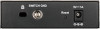
1 Product Introduction Rear Panel D-Link Smart Managed Switch User Manual Figure 1.2 - DGS-1100-05PDV2 2-Port 10/100/1000Mbps PoE and 3-Port 10/100/1000Mbps with 1 PD port Smart Managed Switch. Front Panel Figure 1.3 - Light off : No link. Solid Amber: PD device insert but failure occurs. Solid Amber: Receiving power from PSE per PSE. Light off...
1 Product Introduction Rear Panel D-Link Smart Managed Switch User Manual Figure 1.2 - DGS-1100-05PDV2 2-Port 10/100/1000Mbps PoE and 3-Port 10/100/1000Mbps with 1 PD port Smart Managed Switch. Front Panel Figure 1.3 - Light off : No link. Solid Amber: PD device insert but failure occurs. Solid Amber: Receiving power from PSE per PSE. Light off...

User Manual 1.00 WW
Page 8
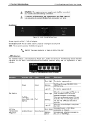
... DGS-1100-08PV2 Front Panel Power LED: The Power LED lights up the device and enter loader mode. The LED will blink 5 seconds. PoE total power budget shortage. 2. DGS-1100-08PV2 8-Port 10/100/1000Mbps PoE Smart Managed Switch. Alternatively, you can be powered for 2 seconds. Link/Act.../Speed LED (Ports 1-8): Flashing: Indicates a network link through the corresponding port.
... DGS-1100-08PV2 Front Panel Power LED: The Power LED lights up the device and enter loader mode. The LED will blink 5 seconds. PoE total power budget shortage. 2. DGS-1100-08PV2 8-Port 10/100/1000Mbps PoE Smart Managed Switch. Alternatively, you can be powered for 2 seconds. Link/Act.../Speed LED (Ports 1-8): Flashing: Indicates a network link through the corresponding port.
User Manual 1.00 WW
Page 9
... Solid Light The device is being processed on . LED Indicators The Switches feature LED indicators for Power and Link/Act for the DGS-1100-05V2/05PDV2/08V2/08PV2 switches along with earthing connection. PoE Max. (Only DGS-1100- Red 08PV2) Solid Light Blinking When the power output to ground. No additional PDs can be connected to a socket...
... Solid Light The device is being processed on . LED Indicators The Switches feature LED indicators for Power and Link/Act for the DGS-1100-05V2/05PDV2/08V2/08PV2 switches along with earthing connection. PoE Max. (Only DGS-1100- Red 08PV2) Solid Light Blinking When the power output to ground. No additional PDs can be connected to a socket...

User Manual 1.00 WW
Page 10
... this port. PD Status 05PDV2 only) Solid Amber Indicates there is not enough.) Light off No link. 7 1 Product Introduction D-Link Smart Managed Switch User Manual LED Per PoE Port PoE Status LED Per PD Port (DGS-1100- Light off No PD device inserts. Light off Indicates there is being processed on this port. Blinking...
... this port. PD Status 05PDV2 only) Solid Amber Indicates there is not enough.) Light off No link. 7 1 Product Introduction D-Link Smart Managed Switch User Manual LED Per PoE Port PoE Status LED Per PD Port (DGS-1100- Light off No PD device inserts. Light off Indicates there is being processed on this port. Blinking...

User Manual 1.00 WW
Page 11
...Make sure that it is secured fully to see that there is found missing or damaged, please contact the local reseller for your D-Link DGS-110005V2/05PDV2/08V2/08PV2 Smart Managed Switch. Figure 2.1 - Attach the adhesive rubber pads to the bottom Wall-mount The Switch can be mounted on the...it is places on the bottom panel of four adhesive rubber pads that align with the keyholes on a wall. Desktop or Shelf Installation The DGS-1100 series switches come with a strip of the Switch. Step 2: Drive the included screws into the drilled holes. Do not place heavy objects...
...Make sure that it is secured fully to see that there is found missing or damaged, please contact the local reseller for your D-Link DGS-110005V2/05PDV2/08V2/08PV2 Smart Managed Switch. Figure 2.1 - Attach the adhesive rubber pads to the bottom Wall-mount The Switch can be mounted on the...it is places on the bottom panel of four adhesive rubber pads that align with the keyholes on a wall. Desktop or Shelf Installation The DGS-1100 series switches come with a strip of the Switch. Step 2: Drive the included screws into the drilled holes. Do not place heavy objects...
User Manual 1.00 WW
Page 12
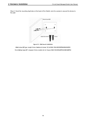
Wall mount installation Metal screw (M7 type; 2 Hardware Installation D-Link Smart Managed Switch User Manual Step 2. Hook the mounting keyholes on the back of screws *2) for DGS-1100-05V2/05PDV2/08V2/08PV2 Vis métallique (type M7 ; Length 16 mm, Number of the Switch onto the screws to secure the device to the wall. longueur 16 mm, nombre de vis *2) pour DGS-1100-05V2/05PDV2/08V2/08PV2 9 Figure 2.2 -
Wall mount installation Metal screw (M7 type; 2 Hardware Installation D-Link Smart Managed Switch User Manual Step 2. Hook the mounting keyholes on the back of screws *2) for DGS-1100-05V2/05PDV2/08V2/08PV2 Vis métallique (type M7 ; Length 16 mm, Number of the Switch onto the screws to secure the device to the wall. longueur 16 mm, nombre de vis *2) pour DGS-1100-05V2/05PDV2/08V2/08PV2 9 Figure 2.2 -
User Manual 1.00 WW
Page 13
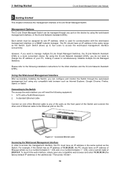
... with a RJ45 Ethernet port. 2. Connected Ethernet cable Accessing the Web-based Management Interface In order to simultaneously initialize multiple D-Link Managed Switches. Management Options The D-Link Smart Managed Switch can configure and monitor the Switch through any compatible web browser such as the Switch. By using the... interface, the PC must be managed through the web-based management tool using the web-based management interface, or the D-Link Network Assistant (DNA). However, if you can be assigned its own IP address, which is used for the Web interface and the...
... with a RJ45 Ethernet port. 2. Connected Ethernet cable Accessing the Web-based Management Interface In order to simultaneously initialize multiple D-Link Managed Switches. Management Options The D-Link Smart Managed Switch can configure and monitor the Switch through any compatible web browser such as the Switch. By using the... interface, the PC must be managed through the web-based management tool using the web-based management interface, or the D-Link Network Assistant (DNA). However, if you can be assigned its own IP address, which is used for the Web interface and the...
User Manual 1.00 WW
Page 14
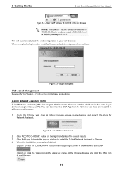
...button in the upper-right corner of the window to continue. Figure 3.4 - Click 'Add app' button in the pop-up window to install the D-Link Network Assistant in , enter the default password admin and press ok to start the app. 11 When prompted to start DNA. (Option 2) Click the...2 network segment as your web browser. Figure 3.3 - Click 'ADD TO CHROME' button on the right hand side of the search results. 3. D-Link Network Assistant (DNA) D-Link Network Assistant (DNA) is a program that is 10.90.90.90 with a subnet mask of 255.0.0.0 and a default gateway of the Chrome browser...
...button in the upper-right corner of the window to continue. Figure 3.4 - Click 'Add app' button in the pop-up window to install the D-Link Network Assistant in , enter the default password admin and press ok to start the app. 11 When prompted to start DNA. (Option 2) Click the...2 network segment as your web browser. Figure 3.3 - Click 'ADD TO CHROME' button on the right hand side of the search results. 3. D-Link Network Assistant (DNA) D-Link Network Assistant (DNA) is a program that is 10.90.90.90 with a subnet mask of 255.0.0.0 and a default gateway of the Chrome browser...

User Manual 1.00 WW
Page 15
...firmware upgrades and basic settings. NOTE: If you will be configured through the web-based management interface. Click this to the local D-Link website. 12 The Tool Bar provides a quick and convenient way for accessing essential functions such as an abnormal exit and the login ... Tool Bar on top, the Function Tree on the D-Link logo in the main configuration screen. Under the username is the Logout button. 4 Configuration D-Link Smart Managed Switch User Manual 4 Configuration The features and functions of the D-Link Smart Managed Switch can be redirected to end this session...
...firmware upgrades and basic settings. NOTE: If you will be configured through the web-based management interface. Click this to the local D-Link website. 12 The Tool Bar provides a quick and convenient way for accessing essential functions such as an abnormal exit and the login ... Tool Bar on top, the Function Tree on the D-Link logo in the main configuration screen. Under the username is the Logout button. 4 Configuration D-Link Smart Managed Switch User Manual 4 Configuration The features and functions of the D-Link Smart Managed Switch can be redirected to end this session...

User Manual 1.00 WW
Page 16
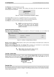
... take effect. Tool Menu > Reset Select a suitable reset option and click Apply to reboot the system. Figure 4.5 - Tool Menu > Firmware Backup and Upgrade 13 4 Configuration D-Link Smart Managed Switch User Manual Tool Bar > Save Menu The Save Menu provides Save Configuration and Save Log functions. Figure 4.7 - Figure 4.3 - Click Yes or No...
... take effect. Tool Menu > Reset Select a suitable reset option and click Apply to reboot the system. Figure 4.5 - Tool Menu > Firmware Backup and Upgrade 13 4 Configuration D-Link Smart Managed Switch User Manual Tool Bar > Save Menu The Save Menu provides Save Configuration and Save Log functions. Figure 4.7 - Figure 4.3 - Click Yes or No...
User Manual 1.00 WW
Page 17
.... Tool Menu > Configure Backup and Restore Backup current settings to file: Specify to back up the current settings of online support: D-Link Support Site will enter boot-loader mode and the following sections provide a more detailed description of the screen. Figure 4.10 - Click ...Upgrade to your disk. 4 Configuration D-Link Smart Managed Switch User Manual Click Backup to save the firmware to update the device's firmware using the selected firmware file. Click Reboot ...
.... Tool Menu > Configure Backup and Restore Backup current settings to file: Specify to back up the current settings of online support: D-Link Support Site will enter boot-loader mode and the following sections provide a more detailed description of the screen. Figure 4.10 - Click ...Upgrade to your disk. 4 Configuration D-Link Smart Managed Switch User Manual Click Backup to save the firmware to update the device's firmware using the selected firmware file. Click Reboot ...
User Manual 1.00 WW
Page 18
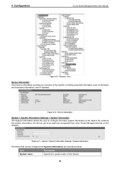
By entering the system information, the device can be recognized from other Smart Managed devices on the network. Figure 4.13 - 4 Configuration D-Link Smart Managed Switch User Manual Figure 4.11 -Function Tree Device Information The Device Information provides an overview of the Switch. Device Information System > System Information ...
By entering the system information, the device can be recognized from other Smart Managed devices on the network. Figure 4.13 - 4 Configuration D-Link Smart Managed Switch User Manual Figure 4.11 -Function Tree Device Information The Device Information provides an overview of the Switch. Device Information System > System Information ...
User Manual 1.00 WW
Page 19
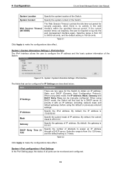
... to 36000 seconds, and the default setting is 0.0.0.0 DHCP Retry Time (5120) Specify the number of all ports can be monitored and configured. 16 4 Configuration D-Link Smart Managed Switch User Manual System Location Specify the system location of the Switch. By default, the gateway is 180 seconds. Table 4.2 Click Apply to...
... to 36000 seconds, and the default setting is 0.0.0.0 DHCP Retry Time (5120) Specify the number of all ports can be monitored and configured. 16 4 Configuration D-Link Smart Managed Switch User Manual System Location Specify the system location of the Switch. By default, the gateway is 180 seconds. Table 4.2 Click Apply to...

User Manual 1.00 WW
Page 20
... Description Specify a description for Port Settings are advertised during auto-negotiation. 4 Configuration D-Link Smart Managed Switch User Manual Figure 4.15 - System > Port Configuration > Jumbo Frame D-Link Smart Managed Switches support jumbo frames (frames larger than the Ethernet frame size of 1536... is disabled by default. This function is Disabled. System > Port Configuration > Jumbo Frame System > PoE > PoE System (DGS-1100-05PDV2/08PV2 only) The PoE System page will display the PoE status including System Budget Power, Support Total Power, Remainder Power, and the...
... Description Specify a description for Port Settings are advertised during auto-negotiation. 4 Configuration D-Link Smart Managed Switch User Manual Figure 4.15 - System > Port Configuration > Jumbo Frame D-Link Smart Managed Switches support jumbo frames (frames larger than the Ethernet frame size of 1536... is disabled by default. This function is Disabled. System > Port Configuration > Jumbo Frame System > PoE > PoE System (DGS-1100-05PDV2/08PV2 only) The PoE System page will display the PoE status including System Budget Power, Support Total Power, Remainder Power, and the...

User Manual 1.00 WW
Page 21
... the switch. The percentage of system supplied Displays the percentage of system power supplied of this switch. PoE Output 15.4 Watts 18 Watts DGS-1100-08PV2 Port 1 ~ Port 8: Max. 4 Configuration D-Link Smart Managed Switch User Manual Figure 4.17 - Power Left Displays the spare power of the switch. The PoE port specification is between 7.1 and...
... the switch. The percentage of system supplied Displays the percentage of system power supplied of this switch. PoE Output 15.4 Watts 18 Watts DGS-1100-08PV2 Port 1 ~ Port 8: Max. 4 Configuration D-Link Smart Managed Switch User Manual Figure 4.17 - Power Left Displays the spare power of the switch. The PoE port specification is between 7.1 and...

User Manual 1.00 WW
Page 22
... is over 375mA in 802.3af mode or 625mA in DGS-1100-08P only.) Legacy Support Specify to enable or disable detecting legacy PDs signal Power Limit This function allows you to manually set the port power current limitation to the PD. 4 Configuration D-Link Smart Managed Switch User Manual 0 Default 1 Optional 2 Optional 3... Port / To Port to manually assign an upper limit of the port when the power is overloaded. please "Refresh" to configure PoE function for DGS-1100-08PV2) to control the PoE functions of the connected PD; Select from 1000 to 8000 milliwatts for...
... is over 375mA in 802.3af mode or 625mA in DGS-1100-08P only.) Legacy Support Specify to enable or disable detecting legacy PDs signal Power Limit This function allows you to manually set the port power current limitation to the PD. 4 Configuration D-Link Smart Managed Switch User Manual 0 Default 1 Optional 2 Optional 3... Port / To Port to manually assign an upper limit of the port when the power is overloaded. please "Refresh" to configure PoE function for DGS-1100-08PV2) to control the PoE functions of the connected PD; Select from 1000 to 8000 milliwatts for...


