
User Manual
Page 2
... 5 Camera Enclosure Disassembly and SD Card Installation 6 Hardware Reset 7 Preparing for Installation 8 Adjusting the Zoom/Focus 10 Flush Mount (DCS-33-1 11 Surface Mount (DCS-33-2 13 Pendant Mount (DCS-33-3 15 Bent Mount (DCS-33-4 17 Network and Power Connections 19 Configuration 21 Configuration with Wizard 21 Web-based Configuration Utility 26 Live... Backup and Restore 55 Firmware Upgrade 56 Status 57 Device Info 57 Logs 58 Help 59 Appendix 60 DI/DO Schematics 60 Technical Specifications 61 D-Link DCS-6510 User Manual 2
... 5 Camera Enclosure Disassembly and SD Card Installation 6 Hardware Reset 7 Preparing for Installation 8 Adjusting the Zoom/Focus 10 Flush Mount (DCS-33-1 11 Surface Mount (DCS-33-2 13 Pendant Mount (DCS-33-3 15 Bent Mount (DCS-33-4 17 Network and Power Connections 19 Configuration 21 Configuration with Wizard 21 Web-based Configuration Utility 26 Live... Backup and Restore 55 Firmware Upgrade 56 Status 57 Device Info 57 Logs 58 Help 59 Appendix 60 DI/DO Schematics 60 Technical Specifications 61 D-Link DCS-6510 User Manual 2
User Manual
Page 3
... of their respective companies. D-Link DCS-6510 User Manual 3 This publication may not be reproduced, in whole or in the United States or other company or product names mentioned herein are trademarks or registered trademarks of D-Link Corporation or its subsidiaries in ...hereof without prior expressed written permission from D-Link Systems, Inc. Copyright © 2010 by D-Link Systems, Inc. Manual Revisions Revision 1.0 Date July 1, 2010 Description DCS-6510 Revision A1 with firmware version 1.00 Trademarks D-Link and the D-Link logo are trademarks or registered trademarks of...
... of their respective companies. D-Link DCS-6510 User Manual 3 This publication may not be reproduced, in whole or in the United States or other company or product names mentioned herein are trademarks or registered trademarks of D-Link Corporation or its subsidiaries in ...hereof without prior expressed written permission from D-Link Systems, Inc. Copyright © 2010 by D-Link Systems, Inc. Manual Revisions Revision 1.0 Date July 1, 2010 Description DCS-6510 Revision A1 with firmware version 1.00 Trademarks D-Link and the D-Link logo are trademarks or registered trademarks of...
User Manual
Page 4
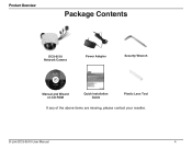
Product Overview Package Contents DCS-6510 Network Camera Power Adapter Security Wrench Manual and Wizard on CD-ROM Quick Installation Guide Plastic Lens Tool If any of the above items are missing, please contact your reseller. D-Link DCS-6510 User Manual 4
Product Overview Package Contents DCS-6510 Network Camera Power Adapter Security Wrench Manual and Wizard on CD-ROM Quick Installation Guide Plastic Lens Tool If any of the above items are missing, please contact your reseller. D-Link DCS-6510 User Manual 4

User Manual
Page 5
Installation Hardware Overview Ethernet Jack RJ-45 connector for Ethernet which can also be used to power the camera using Power over Ethernet (PoE) BNC Connector Analog video output Power Connector Connects to 12 V DC Power adapter Infrared LEDs Used to illuminate the camera's field of view at night Camera Lens DC iris varifocal lens D-Link DCS-6510 User Manual Power Wiring Connects to 24 V AC power Audio Wiring Audio Input / Output DI/DO Wiring I/O connectors for external devices Vandal-proof Cover Protects the camera from damage 5
Installation Hardware Overview Ethernet Jack RJ-45 connector for Ethernet which can also be used to power the camera using Power over Ethernet (PoE) BNC Connector Analog video output Power Connector Connects to 12 V DC Power adapter Infrared LEDs Used to illuminate the camera's field of view at night Camera Lens DC iris varifocal lens D-Link DCS-6510 User Manual Power Wiring Connects to 24 V AC power Audio Wiring Audio Input / Output DI/DO Wiring I/O connectors for external devices Vandal-proof Cover Protects the camera from damage 5
User Manual
Page 6
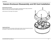
Install the SD Card Push the SD card into the slot. To eject the SD card, push the SD card into the camera with the gold contacts oriented towards the base of the camera. Remove the 4th screw using a screwdriver. Lift the dome off of the base of the camera. D-Link DCS-6510 User Manual 6 Installation Camera Enclosure Disassembly and SD Card Installation Disassemble the Camera Open the camera enclosure by removing the 3 standard screws using the provided security wrench.
Install the SD Card Push the SD card into the slot. To eject the SD card, push the SD card into the camera with the gold contacts oriented towards the base of the camera. Remove the 4th screw using a screwdriver. Lift the dome off of the base of the camera. D-Link DCS-6510 User Manual 6 Installation Camera Enclosure Disassembly and SD Card Installation Disassemble the Camera Open the camera enclosure by removing the 3 standard screws using the provided security wrench.
User Manual
Page 7
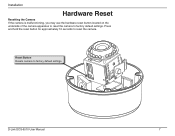
Reset Button Resets camera to factory default settings. Installation Hardware Reset Resetting the Camera If the camera is malfunctioning, you may use the hardware reset button located on the underside of the camera apparatus to reset the camera to factory default settings D-Link DCS-6510 User Manual 7 Press and hold the reset button for approximately 10 seconds to reset the camera.
Reset Button Resets camera to factory default settings. Installation Hardware Reset Resetting the Camera If the camera is malfunctioning, you may use the hardware reset button located on the underside of the camera apparatus to reset the camera to factory default settings D-Link DCS-6510 User Manual 7 Press and hold the reset button for approximately 10 seconds to reset the camera.

User Manual
Page 8
... change the orientation of the camera base rather than the top. Lift the camera bracket off of the base and out of the camera. (Figure 4.) D-Link DCS-6510 User Manual Figure 3. For instance, when using a screwdriver. (Figure 1.) Figure 1. 3. Disconnect the cables from the circuit board at the base of the way. (Figure 3.) 5. Changing Cable Orientation...
... change the orientation of the camera base rather than the top. Lift the camera bracket off of the base and out of the camera. (Figure 4.) D-Link DCS-6510 User Manual Figure 3. For instance, when using a screwdriver. (Figure 1.) Figure 1. 3. Disconnect the cables from the circuit board at the base of the way. (Figure 3.) 5. Changing Cable Orientation...
User Manual
Page 9
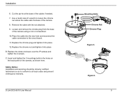
... nut where the cable exits the base of the camera, as to conform to the circuit board. 11. Remove the cable with the nut attached. 9. D-Link DCS-6510 User Manual Mounting Bolts Chrome Nut Chrome Plug Figure 5. Place the cable into place B. Installation 6.
... nut where the cable exits the base of the camera, as to conform to the circuit board. 11. Remove the cable with the nut attached. 9. D-Link DCS-6510 User Manual Mounting Bolts Chrome Nut Chrome Plug Figure 5. Place the cable into place B. Installation 6.

User Manual
Page 10
... and Focus of the Lens Module Please use the included plastic lens tool to adjust the IP camera's image until the desired orientation is achieved. D-Link DCS-6510 User Manual 10 Adjust the zoom factor by moving the controller left and right until the desired range is achieved, tighten the image adjustment screw once completed...
... and Focus of the Lens Module Please use the included plastic lens tool to adjust the IP camera's image until the desired orientation is achieved. D-Link DCS-6510 User Manual 10 Adjust the zoom factor by moving the controller left and right until the desired range is achieved, tighten the image adjustment screw once completed...
User Manual
Page 11
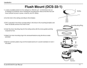
Ceiling Inner Mounting Ring Ceiling Recessed Bracket Plastic Ring D-Link DCS-6510 User Manual Dome Camera 11 Drill 3 separate 6 mm holes corresponding to the holes in marking the mounting hole. Slip the cosmetic plastic ring over the bracket and ... screw guides pointing towards the floor. 5. Cut the hole in the ceiling according to the recessed bracket using the three screws provided. 6. Installation Flush Mount (DCS-33-1) 1. Insert the inner mounting ring into place. Ensure that this hole will have sufficient access to be cut. Locate a suitable position on the ceiling...
Ceiling Inner Mounting Ring Ceiling Recessed Bracket Plastic Ring D-Link DCS-6510 User Manual Dome Camera 11 Drill 3 separate 6 mm holes corresponding to the holes in marking the mounting hole. Slip the cosmetic plastic ring over the bracket and ... screw guides pointing towards the floor. 5. Cut the hole in the ceiling according to the recessed bracket using the three screws provided. 6. Installation Flush Mount (DCS-33-1) 1. Insert the inner mounting ring into place. Ensure that this hole will have sufficient access to be cut. Locate a suitable position on the ceiling...
User Manual
Page 12
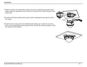
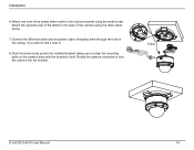
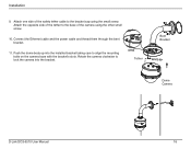
Attach the opposite side of the tether to the base of the safety tether cable to the inner mounting ring using the other small screw. 8. Rotate the camera clockwise to align the mounting bolts on the camera base with the bracket's slots. Tether D-Link DCS-6510 User Manual 12 Connect the Ethernet cable and the power cable, threading them through the hole in the ceiling. 9. Installation 7. Attach one side of the camera using the small screw. Push the dome body up into the installed bracket taking care to lock the camera into the bracket.
Attach the opposite side of the tether to the base of the safety tether cable to the inner mounting ring using the other small screw. 8. Rotate the camera clockwise to align the mounting bolts on the camera base with the bracket's slots. Tether D-Link DCS-6510 User Manual 12 Connect the Ethernet cable and the power cable, threading them through the hole in the ceiling. 9. Installation 7. Attach one side of the camera using the small screw. Push the dome body up into the installed bracket taking care to lock the camera into the bracket.

User Manual
Page 13
... plastic anchors into place. Drill 3 separate 6 mm holes corresponding to the ceiling using the screws provided. 5. Ceiling Surface Bracket Plastic Ring Dome Camera D-Link DCS-6510 User Manual 13 Installation Surface Mount (DCS-33-2) 1. Note: If you will not drill a hole for the cable, please see page 8 for a 45 mm (+2 / -0 mm) hole to the template 3. Slip...
... plastic anchors into place. Drill 3 separate 6 mm holes corresponding to the ceiling using the screws provided. 5. Ceiling Surface Bracket Plastic Ring Dome Camera D-Link DCS-6510 User Manual 13 Installation Surface Mount (DCS-33-2) 1. Note: If you will not drill a hole for the cable, please see page 8 for a 45 mm (+2 / -0 mm) hole to the template 3. Slip...
User Manual
Page 14
Attach one side of the safety tether cable to align the mounting bolts on the camera base with the bracket's slots. Rotate the camera clockwise to lock the camera into the installed bracket taking care to the surface bracket using the other small screw. 7. Installation 6. Attach the opposite side of the camera using the small screw. Tether D-Link DCS-6510 User Manual 14 Connect the Ethernet cable and the power cable, threading them through the hole in the ceiling. If you did not drill a hole to the base of the tether to 8. Push the dome body up into the bracket.
Attach one side of the safety tether cable to align the mounting bolts on the camera base with the bracket's slots. Rotate the camera clockwise to lock the camera into the installed bracket taking care to the surface bracket using the other small screw. 7. Installation 6. Attach the opposite side of the camera using the small screw. Tether D-Link DCS-6510 User Manual 14 Connect the Ethernet cable and the power cable, threading them through the hole in the ceiling. If you did not drill a hole to the base of the tether to 8. Push the dome body up into the bracket.
User Manual
Page 15
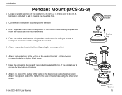
... the bracket cap to secure the bracket cap into these holes. 4. D-Link DCS-6510 User Manual Tether Dome Camera 15 Cut the hole in the ceiling according to ensure a waterproof seal between the ceiling and the bracket. 5. Pendant Bracket Bracket Cap 6. Installation Pendant Mount (DCS-33-3) 1. Attach the pendant bracket to tighten it into place. 7. Attach...
... the bracket cap to secure the bracket cap into these holes. 4. D-Link DCS-6510 User Manual Tether Dome Camera 15 Cut the hole in the ceiling according to ensure a waterproof seal between the ceiling and the bracket. 5. Pendant Bracket Bracket Cap 6. Installation Pendant Mount (DCS-33-3) 1. Attach the pendant bracket to tighten it into place. 7. Attach...
User Manual
Page 16
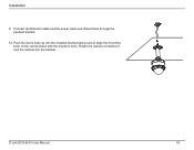
Rotate the camera clockwise to align the mounting bolts on the camera base with the bracket's slots. Push the dome body up into the installed bracket taking care to lock the camera into the bracket. D-Link DCS-6510 User Manual 16 Connect the Ethernet cable and the power cable and thread them through the pendant bracket. 10. Installation 9.
Rotate the camera clockwise to align the mounting bolts on the camera base with the bracket's slots. Push the dome body up into the installed bracket taking care to lock the camera into the bracket. D-Link DCS-6510 User Manual 16 Connect the Ethernet cable and the power cable and thread them through the pendant bracket. 10. Installation 9.
User Manual
Page 17
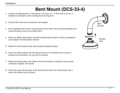
Insert the screw into these holes. 4. Bent Bracket Bracket Cap D-Link DCS-6510 User Manual 17 Cut the hole in the wall according to the holes in marking the mounting hole. 2. Drill 4 separate 6 mm holes corresponding to the template 3. Attach ... a waterproof seal between the bent bracket and the wall to be cut. Place the rubber seal between the wall and the bracket. 5. Installation Bent Mount (DCS-33-4) 1. A template is included to secure the bracket cap into place. 8.
Insert the screw into these holes. 4. Bent Bracket Bracket Cap D-Link DCS-6510 User Manual 17 Cut the hole in the wall according to the holes in marking the mounting hole. 2. Drill 4 separate 6 mm holes corresponding to the template 3. Attach ... a waterproof seal between the bent bracket and the wall to be cut. Place the rubber seal between the wall and the bracket. 5. Installation Bent Mount (DCS-33-4) 1. A template is included to secure the bracket cap into place. 8.
User Manual
Page 18
Connect the Ethernet cable and the power cable and thread them through the bent bracket. 11. Rotate the camera clockwise to lock the camera into the installed bracket taking care to the bracket cap using the other small screw. 10. Tether Bent Bracket Dome Camera D-Link DCS-6510 User Manual 18 Installation 9. Push the dome body up into the bracket. Attach one side of the camera using the small screw. Attach the opposite side of the tether to the base of the safety tether cable to align the mounting bolts on the camera base with the bracket's slots.
Connect the Ethernet cable and the power cable and thread them through the bent bracket. 11. Rotate the camera clockwise to lock the camera into the installed bracket taking care to the bracket cap using the other small screw. 10. Tether Bent Bracket Dome Camera D-Link DCS-6510 User Manual 18 Installation 9. Push the dome body up into the bracket. Attach one side of the camera using the small screw. Attach the opposite side of the tether to the base of the safety tether cable to align the mounting bolts on the camera base with the bracket's slots.
User Manual
Page 19
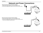
Connect the network camera to a power outlet. Connect the supplied power cable from the camera to a hub via an Ethernet cable. 2. Connect the supplied power cable from the camera to a hub via an Ethernet cable. 2. D-Link DCS-6510 User Manual 19 Installation Network and Power Connections General Connection Using 12 V DC Power Adapter 1. Connect the network camera to a power source such as your building's emergency power. General Connection Using 24 V AC Power Wiring 1.
Connect the network camera to a power outlet. Connect the supplied power cable from the camera to a hub via an Ethernet cable. 2. Connect the supplied power cable from the camera to a hub via an Ethernet cable. 2. D-Link DCS-6510 User Manual 19 Installation Network and Power Connections General Connection Using 12 V DC Power Adapter 1. Connect the network camera to a power source such as your building's emergency power. General Connection Using 24 V AC Power Wiring 1.
User Manual
Page 20
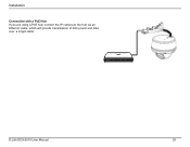
Installation Connection with a PoE Hub If you are using a PoE hub, connect the IP camera to the hub via an Ethernet cable, which will provide transmission of both power and data over a single cable. D-Link DCS-6510 User Manual 20
Installation Connection with a PoE Hub If you are using a PoE hub, connect the IP camera to the hub via an Ethernet cable, which will provide transmission of both power and data over a single cable. D-Link DCS-6510 User Manual 20
User Manual
Page 21
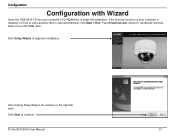
Click Setup Wizard to continue. Click Next to begin the installation. D-Link DCS-6510 User Manual 21 After clicking Setup Wizard, the window on your computer's CD-ROM drive to begin the installation. If the Autorun function on the right will open. Configuration Configuration with Wizard Insert the DCS-6510 CD into your computer is disabled, or if the D-Link Launcher fails to start automatically, click Start > Run. Type D:\autorun.exe, where D: represents the drive letter of your CD-ROM drive.
Click Setup Wizard to continue. Click Next to begin the installation. D-Link DCS-6510 User Manual 21 After clicking Setup Wizard, the window on your computer's CD-ROM drive to begin the installation. If the Autorun function on the right will open. Configuration Configuration with Wizard Insert the DCS-6510 CD into your computer is disabled, or if the D-Link Launcher fails to start automatically, click Start > Run. Type D:\autorun.exe, where D: represents the drive letter of your CD-ROM drive.


