
User Manual
Page 2
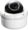
... 4 Installation 5 Hardware Overview 5 Camera Enclosure Disassembly and SD Card Installation 6 Hardware Reset 7 Preparing for Installation 8 Adjusting the Zoom/Focus 10 Flush Mount (DCS-33-1 11 Surface Mount (DCS-33-2 13 Pendant Mount (DCS-33-3 15 Bent Mount (DCS-33-4 17 Network and Power Connections 19 Configuration 21 Configuration with Wizard 21 Web-based Configuration Utility 26 Live Video 28... Backup and Restore 55 Firmware Upgrade 56 Status 57 Device Info 57 Logs 58 Help 59 Appendix 60 DI/DO Schematics 60 Technical Specifications 61 D-Link DCS-6510 User Manual 2
... 4 Installation 5 Hardware Overview 5 Camera Enclosure Disassembly and SD Card Installation 6 Hardware Reset 7 Preparing for Installation 8 Adjusting the Zoom/Focus 10 Flush Mount (DCS-33-1 11 Surface Mount (DCS-33-2 13 Pendant Mount (DCS-33-3 15 Bent Mount (DCS-33-4 17 Network and Power Connections 19 Configuration 21 Configuration with Wizard 21 Web-based Configuration Utility 26 Live Video 28... Backup and Restore 55 Firmware Upgrade 56 Status 57 Device Info 57 Logs 58 Help 59 Appendix 60 DI/DO Schematics 60 Technical Specifications 61 D-Link DCS-6510 User Manual 2

User Manual
Page 8
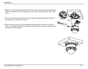
... do not remove, the two screws that secure the camera bracket to the base of the enclosure using the Surface Mounting Bracket, the cables may need to change the orientation of the camera. (Figure 4.) D-Link DCS-6510 User Manual Figure 3. Changing Cable Orientation: 1. Slide the camera bracket towards the front of the way. (Figure ...the cables from the circuit board at the base of the cable. Disassemble the camera enclosure. (See Figure A. Figure 2. on how you choose to mount the camera, you may need to exit through the side of the camera base rather than the top.
... do not remove, the two screws that secure the camera bracket to the base of the enclosure using the Surface Mounting Bracket, the cables may need to change the orientation of the camera. (Figure 4.) D-Link DCS-6510 User Manual Figure 3. Changing Cable Orientation: 1. Slide the camera bracket towards the front of the way. (Figure ...the cables from the circuit board at the base of the cable. Disassemble the camera enclosure. (See Figure A. Figure 2. on how you choose to mount the camera, you may need to exit through the side of the camera base rather than the top.

User Manual
Page 13
... and insert the plastic anchors into place. Drill 3 separate 6 mm holes corresponding to the template 3. Ceiling Surface Bracket Plastic Ring Dome Camera D-Link DCS-6510 User Manual 13 Cut the hole in marking the mounting hole. Locate a suitable position on the ceiling for information regarding how to the ceiling using the screws provided. 5. Attach the...
... and insert the plastic anchors into place. Drill 3 separate 6 mm holes corresponding to the template 3. Ceiling Surface Bracket Plastic Ring Dome Camera D-Link DCS-6510 User Manual 13 Cut the hole in marking the mounting hole. Locate a suitable position on the ceiling for information regarding how to the ceiling using the screws provided. 5. Attach the...
User Manual
Page 14
Attach one side of the camera using the small screw. Push the dome body up into the bracket. If you did not drill a hole to the surface bracket using the other small screw. 7. Tether D-Link DCS-6510 User Manual 14 Rotate the camera clockwise to lock the camera into the installed bracket taking care to align the mounting bolts on the camera base with the bracket's slots. Installation 6. Connect the Ethernet cable and the power cable, threading them through the hole in the ceiling. Attach the opposite side of the tether to the base of the safety tether cable to 8.
Attach one side of the camera using the small screw. Push the dome body up into the bracket. If you did not drill a hole to the surface bracket using the other small screw. 7. Tether D-Link DCS-6510 User Manual 14 Rotate the camera clockwise to lock the camera into the installed bracket taking care to align the mounting bolts on the camera base with the bracket's slots. Installation 6. Connect the Ethernet cable and the power cable, threading them through the hole in the ceiling. Attach the opposite side of the tether to the base of the safety tether cable to 8.
