

Operation Manual
Page 2
Sears, Roebuck and Co., Hoffman Estates, IL 60179 / MS-3620MA 2 TABLE OF CONTENTS WARRANTY 2 MAINTENANCE 22 PRODUCT SPECIFICATIONS 3 SERVICE AND ADJUSTMENT 28 SAFETY RULES 4 TROUBLESHOOTING CHART 36 PREPARATION 7 SLOPE GUIDE 39 OPERATION 10 REPAIR PARTS 40 [ This warranty gives you specific legal rights, and you may also have other rights which vary from state to state.
Sears, Roebuck and Co., Hoffman Estates, IL 60179 / MS-3620MA 2 TABLE OF CONTENTS WARRANTY 2 MAINTENANCE 22 PRODUCT SPECIFICATIONS 3 SERVICE AND ADJUSTMENT 28 SAFETY RULES 4 TROUBLESHOOTING CHART 36 PREPARATION 7 SLOPE GUIDE 39 OPERATION 10 REPAIR PARTS 40 [ This warranty gives you specific legal rights, and you may also have other rights which vary from state to state.
Operation Manual
Page 5
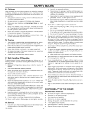
...the fuel tank or container opening at the hitch point. 2. Adjust and service as cracks and nicks. Use oil rated 30 in the summer. • Tune-up oil or fuel spills. Never allow objects to be immediately replaced with a plastic ... securely. d. Children are explosive. 1. Extinguish all nuts and bolts, especially the blade attachment nuts tight. Tow only with manufacturer's recommended parts when necessary. 9. a. Do not change clothing immediately. 10. Travel slowly and allow children to stop before refueling. 4. Gasoline is LP...
...the fuel tank or container opening at the hitch point. 2. Adjust and service as cracks and nicks. Use oil rated 30 in the summer. • Tune-up oil or fuel spills. Never allow objects to be immediately replaced with a plastic ... securely. d. Children are explosive. 1. Extinguish all nuts and bolts, especially the blade attachment nuts tight. Tow only with manufacturer's recommended parts when necessary. 9. a. Do not change clothing immediately. 10. Travel slowly and allow children to stop before refueling. 4. Gasoline is LP...

Operation Manual
Page 7
...PREPARATION Read and follow the instructions below . Pull the tear tape no more than twelve inches at the bottom of someone sitting in the parts bag. Remove the mower from both ends, remove the top wood and set aside. 5. The fasteners are in the operator's seat. _b...your mower. for the location of the tires. 10. All any staples that are shown below . 1. The quantity is assembled. tion of a part from the carton, follow the preparation instructions fasteners are shown full size. Move the lift lever to the neutral (N) position. Do not discard until ...
...PREPARATION Read and follow the instructions below . Pull the tear tape no more than twelve inches at the bottom of someone sitting in the parts bag. Remove the mower from both ends, remove the top wood and set aside. 5. The fasteners are in the operator's seat. _b...your mower. for the location of the tires. 10. All any staples that are shown below . 1. The quantity is assembled. tion of a part from the carton, follow the preparation instructions fasteners are shown full size. Move the lift lever to the neutral (N) position. Do not discard until ...
Operation Manual
Page 20
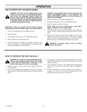
... the SLOW position. 7. Make sure the level of cut is still correct. If you operate with the mower housing, always operate with an original equipment part from a Sears Service Center. Slowly release the pedal. 4. IMPORTANT: When you must stop or change directions on a hill. If you ride up . When on a slope...
... the SLOW position. 7. Make sure the level of cut is still correct. If you operate with the mower housing, always operate with an original equipment part from a Sears Service Center. Slowly release the pedal. 4. IMPORTANT: When you must stop or change directions on a hill. If you ride up . When on a slope...
Operation Manual
Page 23
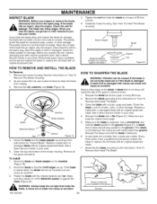
...blaAdReN. See if the blade is _b Aobt lcaodreretchtalyt isbadlaamncaegdedorwifiththecrabclakdse ciasndabmreaagkeda.nd cause an accident. Before you operate the unit, replace damaged parts with an original equipment blade. 7. Tighten the nut that holds the blade to the instructions "How To Remove And install The ... the nut tight. Every three years, have a qualified service person inspect the blade or replace the old blade with original equipment parts. Check the blade and the blade adapter according to the ground. Mount the blade and blade adapter on the mandrel (Figure 19...
...blaAdReN. See if the blade is _b Aobt lcaodreretchtalyt isbadlaamncaegdedorwifiththecrabclakdse ciasndabmreaagkeda.nd cause an accident. Before you operate the unit, replace damaged parts with an original equipment blade. 7. Tighten the nut that holds the blade to the instructions "How To Remove And install The ... the nut tight. Every three years, have a qualified service person inspect the blade or replace the old blade with original equipment parts. Check the blade and the blade adapter according to the ground. Mount the blade and blade adapter on the mandrel (Figure 19...

Operation Manual
Page 27
... season or 100 hours of the spark plug with the air filters (air cleaner cartridge, pre-cleaner) removed. For the correct replacement filter, see the parts list for the air cleaner cover. CAUTION: Do not use . it can damage cartridge; Pull up on the cover with SCREENside up allowing dirt and...
... season or 100 hours of the spark plug with the air filters (air cleaner cartridge, pre-cleaner) removed. For the correct replacement filter, see the parts list for the air cleaner cover. CAUTION: Do not use . it can damage cartridge; Pull up on the cover with SCREENside up allowing dirt and...
Operation Manual
Page 29
...the FAST position. 2. Make sure the brake pad is excessively worn or damaged, replace the brake pad assemblies. Attachment Clutch Engage Position Figure 30 10. Mow for the blade brake, If the pad is pressed tightly against the pulley (Figure 31 ). _ agAaRinNsItNGth:e pIfultlheey, btarakkeethepaudnitdotoesa ...brown. Move the attachment clutch to the DISENGAGE position, all movement will not require an adjustment. Correct replacement parts and assistance are available from a new mower drive belt, If you move the attachment clutch to the DISENGAGE position (Figure...
...the FAST position. 2. Make sure the brake pad is excessively worn or damaged, replace the brake pad assemblies. Attachment Clutch Engage Position Figure 30 10. Mow for the blade brake, If the pad is pressed tightly against the pulley (Figure 31 ). _ agAaRinNsItNGth:e pIfultlheey, btarakkeethepaudnitdotoesa ...brown. Move the attachment clutch to the DISENGAGE position, all movement will not require an adjustment. Correct replacement parts and assistance are available from a new mower drive belt, If you move the attachment clutch to the DISENGAGE position (Figure...
Operation Manual
Page 35
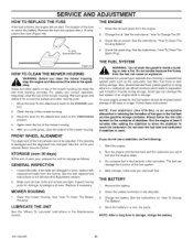
... The Battery". 4. If you do the following: 1. See the instructions on the container of fuel gum in essential fuel system parts such as follows. otDodraniont tshmeogkaesolbineecausinesidtehea fubmuieldsfrom the fuel can damage the fuel system of the fuel system. 4. Also, alcohol blended fuels...Spark Plug". FRONT WHEEL ALIGNMENT The alignment of the front wheels cannot be emptied before storage of the mower housing. STORAGE (over 30 days) At the end of acids during storage. GENERAL INSPECTION 1. MOWER HOUSING 1. To avoid engine problems, the fuel system should...
... The Battery". 4. If you do the following: 1. See the instructions on the container of fuel gum in essential fuel system parts such as follows. otDodraniont tshmeogkaesolbineecausinesidtehea fubmuieldsfrom the fuel can damage the fuel system of the fuel system. 4. Also, alcohol blended fuels...Spark Plug". FRONT WHEEL ALIGNMENT The alignment of the front wheels cannot be emptied before storage of the mower housing. STORAGE (over 30 days) At the end of acids during storage. GENERAL INSPECTION 1. MOWER HOUSING 1. To avoid engine problems, the fuel system should...
Operation Manual
Page 36
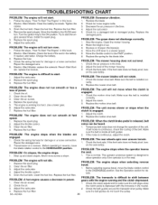
... a damaged belt or damaged pulley. Replace the fuel filter. Check the oil. Replace the fuel filter. 2. PROBLEM: The engine will not idle. 1. Replace the damaged parts. Replace the fuse. 4. Electric-Start Models: replace the solenoid. Adjust the carburetor. 2. Replace the spark plug. 5. rectly. 2. Replace the fuel filter. Replace the motion drive...
... a damaged belt or damaged pulley. Replace the fuel filter. Check the oil. Replace the fuel filter. 2. PROBLEM: The engine will not idle. 1. Replace the damaged parts. Replace the fuse. 4. Electric-Start Models: replace the solenoid. Adjust the carburetor. 2. Replace the spark plug. 5. rectly. 2. Replace the fuel filter. Replace the motion drive...
Operation Manual
Page 37
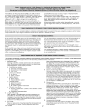
...anti-smog standards. Fuel Metering System [] Cold start enrichment system [] Carburetor and internal parts the diagnostic work is delivered to the owner, including diagnostic labor which are pleased to exceed 30 days. The California Air Resources Board (CARB), U.S. EPA and Sears are not original... Sears parts or because of abuse, neglect or improper maintenance as required maintenance shall be ...
...anti-smog standards. Fuel Metering System [] Cold start enrichment system [] Carburetor and internal parts the diagnostic work is delivered to the owner, including diagnostic labor which are pleased to exceed 30 days. The California Air Resources Board (CARB), U.S. EPA and Sears are not original... Sears parts or because of abuse, neglect or improper maintenance as required maintenance shall be ...
Operation Manual
Page 41
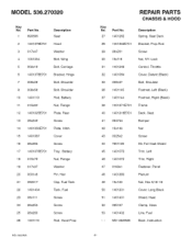
MODEL 536.270320 Key No. Part No. 1 690566 2 1401379E701 3 017x47 4 1001054 5 002xl 6 6 1401378E701 7 009x29 8 009x56 10 1401113 11 015x84 12 1401025E701 13 26x249 14 1401050E701 15 1401087 16 26x263 17 1401076E701 18 015x79 19 017x37 20 0031x6 21 092317 22..., Fuel Screw Screw Screw Rod, Hood Prop MS-3620MA REPAIR PARTS CHASSIS & HOOD Key No. MS-3620MA Book, Instruction 41 Part No. 27 1401282 Description Spring, Seat Deck 28 1401352E701 Bracket, Prop Rod 29 26x201 Screw 30 15x116 Nut, NY-Lock 31 1401248 Control, Throttle 32 1401084 ...
MODEL 536.270320 Key No. Part No. 1 690566 2 1401379E701 3 017x47 4 1001054 5 002xl 6 6 1401378E701 7 009x29 8 009x56 10 1401113 11 015x84 12 1401025E701 13 26x249 14 1401050E701 15 1401087 16 26x263 17 1401076E701 18 015x79 19 017x37 20 0031x6 21 092317 22..., Fuel Screw Screw Screw Rod, Hood Prop MS-3620MA REPAIR PARTS CHASSIS & HOOD Key No. MS-3620MA Book, Instruction 41 Part No. 27 1401282 Description Spring, Seat Deck 28 1401352E701 Bracket, Prop Rod 29 26x201 Screw 30 15x116 Nut, NY-Lock 31 1401248 Control, Throttle 32 1401084 ...
Operation Manual
Page 43
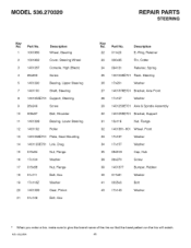
MODEL 536.270320 REPAIR PARTS STEERING Key No. Part No. 1 1001980 Description Wheel, Steering 2 1001982 3 1401067 Cover, Steering Wheel Console, High (Black) 4 26x250 5 1401090 Screw Bearing, Upper Steering 7 1401100 Shaft, Steering 8 1401055E701 Support, Steering 9 26x249 Screw 10 009x67 11 1401098 Bolt, Shoulder Bearing, Lower Steering 12 1401102 Roller 13 1401058E701 Plate, Gear Mounting 14 1401123E701 Link...
MODEL 536.270320 REPAIR PARTS STEERING Key No. Part No. 1 1001980 Description Wheel, Steering 2 1001982 3 1401067 Cover, Steering Wheel Console, High (Black) 4 26x250 5 1401090 Screw Bearing, Upper Steering 7 1401100 Shaft, Steering 8 1401055E701 Support, Steering 9 26x249 Screw 10 009x67 11 1401098 Bolt, Shoulder Bearing, Lower Steering 12 1401102 Roller 13 1401058E701 Plate, Gear Mounting 14 1401123E701 Link...
Operation Manual
Page 45
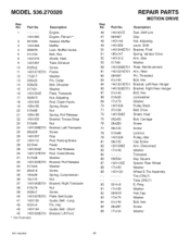
..., Muffler Screw Bolt, Hex Shield, Heat Tube, Exhaust 10 0025x2 Screw 11 1401371 E701 Frame 12 17x217 Washer 13 030x20 14 009x39 15 017x91 Pin, Cotter Bolt, Shoulder Washer 16 1401334Z Plate, Transaxle 17 094815 Nut, Adjusting 18... 66 22 1401300 23 015x84 24 1401268E701 25 26x249 26 1401337 27 1401112 28 021544 29 1401304Z 30 1401127E701 31 017x38 32 1401303E701 33 017x53 34 26x216 35 164x39 36 15x119 37 1401042E701 38 015x79 39...94 01x143 95 26x267 Bolt, Hex Screw 96 17xl 04 Washer MS-3620MA 45 Part No. Part No. MODEL 536.270320 Key No.
..., Muffler Screw Bolt, Hex Shield, Heat Tube, Exhaust 10 0025x2 Screw 11 1401371 E701 Frame 12 17x217 Washer 13 030x20 14 009x39 15 017x91 Pin, Cotter Bolt, Shoulder Washer 16 1401334Z Plate, Transaxle 17 094815 Nut, Adjusting 18... 66 22 1401300 23 015x84 24 1401268E701 25 26x249 26 1401337 27 1401112 28 021544 29 1401304Z 30 1401127E701 31 017x38 32 1401303E701 33 017x53 34 26x216 35 164x39 36 15x119 37 1401042E701 38 015x79 39...94 01x143 95 26x267 Bolt, Hex Screw 96 17xl 04 Washer MS-3620MA 45 Part No. Part No. MODEL 536.270320 Key No.
Operation Manual
Page 47
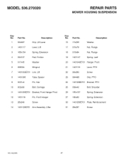
...0031 x4 Pin, Hair 10 002x93 Bolt, Carriage 11 1401030E701 Bracket, Front Hanger Pivot 12 1401118 Pin, Front Hanger 13 26x249 Screw 14 1401129E701 Arm Assembly, Lifter Key No. Part No. 15 17x206 Washer Description 17 015x79 Nut, Flange 18 015x84 Nut, Flange 19 1401147 Spring, Leaf 20 ... 094498 Grip, PTO 24 1401369E701 Bracket, PTO 25 009x42 Bolt, Shoulder 26 165xl 57 Spring, Extension 27 165x92 Spring, Extension 30 1401260E701 Plate, Reinforcement 31 26x267 Screw MS-3620MA 47 MODEL 536.270320 REPAIR PARTS MOWER HOUSING SUSPENSION Key No.
...0031 x4 Pin, Hair 10 002x93 Bolt, Carriage 11 1401030E701 Bracket, Front Hanger Pivot 12 1401118 Pin, Front Hanger 13 26x249 Screw 14 1401129E701 Arm Assembly, Lifter Key No. Part No. 15 17x206 Washer Description 17 015x79 Nut, Flange 18 015x84 Nut, Flange 19 1401147 Spring, Leaf 20 ... 094498 Grip, PTO 24 1401369E701 Bracket, PTO 25 009x42 Bolt, Shoulder 26 165xl 57 Spring, Extension 27 165x92 Spring, Extension 30 1401260E701 Plate, Reinforcement 31 26x267 Screw MS-3620MA 47 MODEL 536.270320 REPAIR PARTS MOWER HOUSING SUSPENSION Key No.
Operation Manual
Page 49
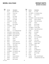
... 22 1401095 Tube, Spacer 23 1401037E701 Bracket, Deck 24 1401040E701 Hanger, Front 26 1401065 Shaft, Splined 27 1401258E701 Arm Assembly, Ldler 28 009x39 Bolt, Shoulder 29 017x47 Washer 30 165xl 57 Spring, Extension 31 166x46 Spring, Torsion 32 009x42 MS-3620MA Bolt, Shoulder Key No. Part No. MODEL 536.270320 REPAIR PARTS MOWER HOUSING Key No.
... 22 1401095 Tube, Spacer 23 1401037E701 Bracket, Deck 24 1401040E701 Hanger, Front 26 1401065 Shaft, Splined 27 1401258E701 Arm Assembly, Ldler 28 009x39 Bolt, Shoulder 29 017x47 Washer 30 165xl 57 Spring, Extension 31 166x46 Spring, Torsion 32 009x42 MS-3620MA Bolt, Shoulder Key No. Part No. MODEL 536.270320 REPAIR PARTS MOWER HOUSING Key No.
Operation Manual
Page 51
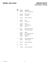
Pa_ No. 250x146 Description Harness, Chassis Wire 1001995 327349 Switch, Ignition Key, Ignition 3 094136 Switch, Limit (PTO) 4 302031 407078 Fuse Holder, Fuse 1002004 26x229 15x116 Solenoid Screw, Mounting Locknut 24x37 26x229 Cable, Battery Ground Screw, Ground Cable 021075 690604 002x82 014x79 024273 26x270 Battery Cover, Battery Terminal Bolt, Carriage Wingnut Switch, Select Reverse" Screw, Mounting 9 094159 10 024x24 Switch, Seat Sensor Cable 11 1001575 Switch, Clutch Brake MS-3620MA 51 MODEL 536.270320 REPAIR PARTS ELECTRICAL SYSTEM Key No.
Pa_ No. 250x146 Description Harness, Chassis Wire 1001995 327349 Switch, Ignition Key, Ignition 3 094136 Switch, Limit (PTO) 4 302031 407078 Fuse Holder, Fuse 1002004 26x229 15x116 Solenoid Screw, Mounting Locknut 24x37 26x229 Cable, Battery Ground Screw, Ground Cable 021075 690604 002x82 014x79 024273 26x270 Battery Cover, Battery Terminal Bolt, Carriage Wingnut Switch, Select Reverse" Screw, Mounting 9 094159 10 024x24 Switch, Seat Sensor Cable 11 1001575 Switch, Clutch Brake MS-3620MA 51 MODEL 536.270320 REPAIR PARTS ELECTRICAL SYSTEM Key No.
Operation Manual
Page 52
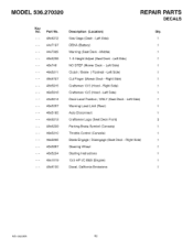
...) 1 Auto Disconnect 1 Craftsman Logo (Seat Deck Front) 2 Parking Brake Symbol (Console) 1 Throttle Control (Console) 1 Blade Engage / Disengage (Seat Deck -Right Side) 1 Steering Wheel 1 Starting Instructions 1 13.5 HP I/C B&S (Engine) 1 Decal, California Emissions 1 MS-3620MA 52 Gas Gage (Dash -Left Side) 1 DEKA (Battery) 1 Warning (Seat Deck -Middle) 1 1-5 Height Adjust (Seat Deck -Left Side) 1 NO STEP (Mower Deck - MODEL 536.270320 Key No.
...) 1 Auto Disconnect 1 Craftsman Logo (Seat Deck Front) 2 Parking Brake Symbol (Console) 1 Throttle Control (Console) 1 Blade Engage / Disengage (Seat Deck -Right Side) 1 Steering Wheel 1 Starting Instructions 1 13.5 HP I/C B&S (Engine) 1 Decal, California Emissions 1 MS-3620MA 52 Gas Gage (Dash -Left Side) 1 DEKA (Battery) 1 Warning (Seat Deck -Middle) 1 1-5 Height Adjust (Seat Deck -Left Side) 1 NO STEP (Mower Deck - MODEL 536.270320 Key No.

Operation Manual
Page 55
BRIGGS & STRATTON ENGINE MODEL 21B807-0326-E1 REPAIR PARTS RER NO. PART NO. DESCRIPTION 25 792305 Piston Assembly (Standard) Note ..... 792642 Piston Assembly (.020" Oversize) 26 792306 Ring Set (Standard) Note ..... 307 691003 Screw (Cylinder Shield) 523 ... Gasket-Breather Screw (Breather Assembly) Tube-Breather Gasket-Crankcase Plug-Oil Drain Crankshaft Seal-Oil (PTO Side) Screw (Crankcase Cover/ Sump) Key-Flywheel REE NO. PART NO. PART NO.
BRIGGS & STRATTON ENGINE MODEL 21B807-0326-E1 REPAIR PARTS RER NO. PART NO. DESCRIPTION 25 792305 Piston Assembly (Standard) Note ..... 792642 Piston Assembly (.020" Oversize) 26 792306 Ring Set (Standard) Note ..... 307 691003 Screw (Cylinder Shield) 523 ... Gasket-Breather Screw (Breather Assembly) Tube-Breather Gasket-Crankcase Plug-Oil Drain Crankshaft Seal-Oil (PTO Side) Screw (Crankcase Cover/ Sump) Key-Flywheel REE NO. PART NO. PART NO.
Operation Manual
Page 57
... 1034 1095 1266 691751 690822 691581 _e691917 1266A _e697123 SeaI-O Ring (Dipstick Tube) Seal-Valve Gasket-Exhaust Screw (Rocker Cover) Gasket-Rocker Cover- PART NO. Rocker Rod-Push Cover (Exhaust) Note ..... 697394 Rod-Push (Intake) Arm-Rocker Guide-Push Rod Gasket Set-Valve SeaI-O (Intake SeaI...-O (Intake Ring Elbow) Ring Elbow) MS-3620MA 57 DESCRIPTION 3 _3910868 5 697396 7Q_2732808 9 _697109 12 _697110 13 690360 20 _690947 33 695760 34 695761 35 691279 36 691279 42 499586 45 690564 50 697361 51Qe_,692137 Seal-Oil (Magneto Side) Head-...
... 1034 1095 1266 691751 690822 691581 _e691917 1266A _e697123 SeaI-O Ring (Dipstick Tube) Seal-Valve Gasket-Exhaust Screw (Rocker Cover) Gasket-Rocker Cover- PART NO. Rocker Rod-Push Cover (Exhaust) Note ..... 697394 Rod-Push (Intake) Arm-Rocker Guide-Push Rod Gasket Set-Valve SeaI-O (Intake SeaI...-O (Intake Ring Elbow) Ring Elbow) MS-3620MA 57 DESCRIPTION 3 _3910868 5 697396 7Q_2732808 9 _697109 12 _697110 13 690360 20 _690947 33 695760 34 695761 35 691279 36 691279 42 499586 45 690564 50 697361 51Qe_,692137 Seal-Oil (Magneto Side) Head-...

Operation Manual
Page 59
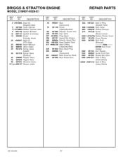
NO. PART NO. PART NO. DESCRIPTION REF. PART NO. DESCRIPTION 187 791805 188 691693 202 691841 209 792602 216 691840 222 694042 227 691374 232 691842 240 3943585 265 691024 267 695134 276 e.... Shaft Cap-Limiter Screw (Float Bowl) SeaI-O Ring (Intake Elbow) SeaI-O Ring (Intake Elbow) MS-3620MA 59 BRIGGS & STRATTON ENGINE MODEL 21B807-0326-E1 REPAIR PARTS RER NO. DESCRIPTION 51Oe_*692137 94 695425 95 e690718 98 695408 104 e694918 105 e696136 108 697723 117 699897 118 699898 121 698787 125 699916...
NO. PART NO. PART NO. DESCRIPTION REF. PART NO. DESCRIPTION 187 791805 188 691693 202 691841 209 792602 216 691840 222 694042 227 691374 232 691842 240 3943585 265 691024 267 695134 276 e.... Shaft Cap-Limiter Screw (Float Bowl) SeaI-O Ring (Intake Elbow) SeaI-O Ring (Intake Elbow) MS-3620MA 59 BRIGGS & STRATTON ENGINE MODEL 21B807-0326-E1 REPAIR PARTS RER NO. DESCRIPTION 51Oe_*692137 94 695425 95 e690718 98 695408 104 e694918 105 e696136 108 697723 117 699897 118 699898 121 698787 125 699916...


