Operation Manual
Page 3
Craftsman... ..... Cutting Height ........... 6 positions from 11/2to 4 inches. Blade Nut Torque ......... 30 foot-pounds (ft-lbs) Power Ratings: The power ratings for an individual engine model ... to meet emissions standards for the muffler. This engine is available on a decal attached to engine and battery. Forward 5.0 mph Reverse 2.5 mph Tilt Seat Access to... Sears Service Center for a spark arrester for 125 hours. Model Number: 536.270320 Serial Number: PRODUCT SPECIFICATIONS Engine 13.5 HP. In the state of California, Model Series 280000 engines are found on this...
Craftsman... ..... Cutting Height ........... 6 positions from 11/2to 4 inches. Blade Nut Torque ......... 30 foot-pounds (ft-lbs) Power Ratings: The power ratings for an individual engine model ... to meet emissions standards for the muffler. This engine is available on a decal attached to engine and battery. Forward 5.0 mph Reverse 2.5 mph Tilt Seat Access to... Sears Service Center for a spark arrester for 125 hours. Model Number: 536.270320 Serial Number: PRODUCT SPECIFICATIONS Engine 13.5 HP. In the state of California, Model Series 280000 engines are found on this...
Operation Manual
Page 4
...when you are involved in a large percentage of the machine. 6. d. or wheel weights when suggested in daylight or good artificial light. 13. If tires lose traction, turn off the blades and proceed slowly straight down before dismounting. 10. Never carry passengers. 6. Always look... down slopes, not across. 2. Never leave a machine unattended with grass baggers or other attachments, they can safely control. Always wear eye protection when you are major factors related to loss-of other people before backing up and...
...when you are involved in a large percentage of the machine. 6. d. or wheel weights when suggested in daylight or good artificial light. 13. If tires lose traction, turn off the blades and proceed slowly straight down before dismounting. 10. Never carry passengers. 6. Always look... down slopes, not across. 2. Never leave a machine unattended with grass baggers or other attachments, they can safely control. Always wear eye protection when you are major factors related to loss-of other people before backing up and...
Operation Manual
Page 5
...bag is an open flame, spark, or pilot light such as a water heater. 2. Check the brake operation frequently. Use oil rated 30 in the summer. • Tune-up the engine regularly. • Keep equipment in handling gasoline. Never allow extra distance to cool for...machine that children will remain where you strike an object. Vl. d. Frequently check the blade(s) for all nuts and bolts, especially the blade attachment nuts tight. Repair, if necessary, before filling. 7. Mower blade(s) are flammable and the vapors MS-3620MA gasoline and other sources of grass...
...bag is an open flame, spark, or pilot light such as a water heater. 2. Check the brake operation frequently. Use oil rated 30 in the summer. • Tune-up the engine regularly. • Keep equipment in handling gasoline. Never allow extra distance to cool for...machine that children will remain where you strike an object. Vl. d. Frequently check the blade(s) for all nuts and bolts, especially the blade attachment nuts tight. Repair, if necessary, before filling. 7. Mower blade(s) are flammable and the vapors MS-3620MA gasoline and other sources of grass...

Operation Manual
Page 7
... CARTON To remove the unit from the viewpoint of the carton. 6. Move the lift lever to the carton and pull again. 4. Literature Kit Side Discharge Attachment MS-3620MA 7 Do not discard until the unit is shown in the path of the controls. 8. Re-grasp the tear tape next to the highest...
... CARTON To remove the unit from the viewpoint of the carton. 6. Move the lift lever to the carton and pull again. 4. Literature Kit Side Discharge Attachment MS-3620MA 7 Do not discard until the unit is shown in the path of the controls. 8. Re-grasp the tear tape next to the highest...

Operation Manual
Page 8
See "How To Charge The Maintenance Free Battery". 3 Remove the protective cap from the battery acid can be attached without charging the battery. If you attach the battery cables to charge the battery. HOW TO CHARGE THE MAINTENANCE FREE BATTERY ,_ WsmAoRkNeI.NGK:eepWthheen baytoteury cahwaragye frothme abnayttesrpya, rkds.o Tnhoet fumes from ...
See "How To Charge The Maintenance Free Battery". 3 Remove the protective cap from the battery acid can be attached without charging the battery. If you attach the battery cables to charge the battery. HOW TO CHARGE THE MAINTENANCE FREE BATTERY ,_ WsmAoRkNeI.NGK:eepWthheen baytoteury cahwaragye frothme abnayttesrpya, rkds.o Tnhoet fumes from ...
Operation Manual
Page 9
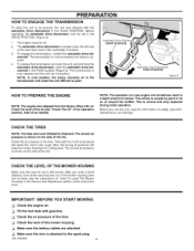
...engine was shipped from cutting level. This is located under the left side of the seat deck next to the hydrostatic transaxle. 3. Check the level of the mower housing, Make sure the battery cables are attached. To release the transmission and push the unit, pull and twist the automatic drive disconnect....be set in the tires. After you use the unit, read the information on the side of the tire. The correct air pressure is attached to the spark plug, MS-3620MA PREPARATION HOW TO ENGAGE THE TRANSMISSION To allow the unit to be pushed, the unit was shipped with gasoline...
...engine was shipped from cutting level. This is located under the left side of the seat deck next to the hydrostatic transaxle. 3. Check the level of the mower housing, Make sure the battery cables are attached. To release the transmission and push the unit, pull and twist the automatic drive disconnect....be set in the tires. After you use the unit, read the information on the side of the tire. The correct air pressure is attached to the spark plug, MS-3620MA PREPARATION HOW TO ENGAGE THE TRANSMISSION To allow the unit to be pushed, the unit was shipped with gasoline...
Operation Manual
Page 10
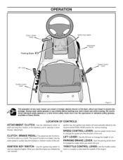
... and to the recommended RUN-MOW position for normal mowing. When you leave the unit. MS-3620MA 10 LOCATION OF CONTROLS ATTACHMENT CLUTCH: Use the attachment clutch to start and stop the rotation of the engine. SPEED CONTROL LEVER: Usethe speed control lever to change the speed ... or standard safety glasses, available at Sears Stores. OPERATION Clutch / Brake Pedal Parkiing Brake Lift Lever Throttle Oontrol Lever Ignition Key Switch Attachment Olutch Speed Control Lever Figure 3 The operation of the unit. Use the brake pedal to engage the brake when you start and stop...
... and to the recommended RUN-MOW position for normal mowing. When you leave the unit. MS-3620MA 10 LOCATION OF CONTROLS ATTACHMENT CLUTCH: Use the attachment clutch to start and stop the rotation of the engine. SPEED CONTROL LEVER: Usethe speed control lever to change the speed ... or standard safety glasses, available at Sears Stores. OPERATION Clutch / Brake Pedal Parkiing Brake Lift Lever Throttle Oontrol Lever Ignition Key Switch Attachment Olutch Speed Control Lever Figure 3 The operation of the unit. Use the brake pedal to engage the brake when you start and stop...
Operation Manual
Page 11
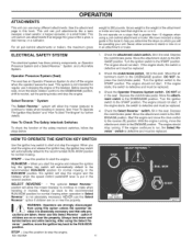
...Presence System and a Select Reverse T'_System, and a Run-Mow System. How To Check The Safety Interlock Switches To check the function of the attachment or trailer and any load that might be replaced. 2. Depress the clutch/brake pedal. The engine should not start , if the engine starts,...KEY SWITCH Use the ignition key switch to the recommended RUN-MOW position for normal mowing. Depress the clutch/brake pedal. Move the attachment clutch to the START position. When you start the engine and release the ignition key, the ignition key switch will automatically default to ...
...Presence System and a Select Reverse T'_System, and a Run-Mow System. How To Check The Safety Interlock Switches To check the function of the attachment or trailer and any load that might be replaced. 2. Depress the clutch/brake pedal. The engine should not start , if the engine starts,...KEY SWITCH Use the ignition key switch to the recommended RUN-MOW position for normal mowing. Depress the clutch/brake pedal. Move the attachment clutch to the START position. When you start the engine and release the ignition key, the ignition key switch will automatically default to ...
Operation Manual
Page 12
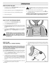
... pedal. 2. The parking brake will hold the unit. 4. Steot tthhee DISENGAGE position. Do not adjust the governor to tow pull behind attachments, control the ground speed with a detent. To stop the unit. To release the parking brake, completely push the clutch/ brake pedal ...Set the parking brake. _IL unAitR. CAUTION: To stop the engine, do not move the throttle control to the STOP O position. Move the attachment clutch to start a cold engine. 2. Figure 5 HOW TO USE THE THROTTLE / CHOKE CONTROL 4. Completely push the clutch/brake pedal forward to...
... pedal. 2. The parking brake will hold the unit. 4. Steot tthhee DISENGAGE position. Do not adjust the governor to tow pull behind attachments, control the ground speed with a detent. To stop the unit. To release the parking brake, completely push the clutch/ brake pedal ...Set the parking brake. _IL unAitR. CAUTION: To stop the engine, do not move the throttle control to the STOP O position. Move the attachment clutch to start a cold engine. 2. Figure 5 HOW TO USE THE THROTTLE / CHOKE CONTROL 4. Completely push the clutch/brake pedal forward to...
Operation Manual
Page 13
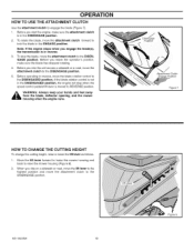
.... If the blade rotation control is moved to the DISENGAGE position. MS-3620MA 13 Figure 8 Before you leave the operator's position, make sure the attachment clutch is in reverse, move the attachment clutch to the DISENGAGE position. 5. Before operating in reverse. 3. Attachment Clutch Engage Position Figure 7 HOW TO CHANGE THE CUTTING HEIGHT To change...
.... If the blade rotation control is moved to the DISENGAGE position. MS-3620MA 13 Figure 8 Before you leave the operator's position, make sure the attachment clutch is in reverse, move the attachment clutch to the DISENGAGE position. 5. Before operating in reverse. 3. Attachment Clutch Engage Position Figure 7 HOW TO CHANGE THE CUTTING HEIGHT To change...

Operation Manual
Page 16
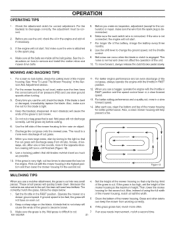
Always operate the engine with the positions of the speed control lever. Lever \ \ Figure 14 MS-3620MA Figure 13 16 FUNCTION Trimming Steep Hills Bagging Grass Normal Mowing Easy Mowing Transport Pull Behind Attachments SPEED CONTROL LEVER POSITION 1/3 1/3 to 1/2 1/2 to 2/3 1/2 to 3/4 FULL 1/3 to the highest position. 3. Raise the lift lever to 1/2 THROTTLE FAST...
Always operate the engine with the positions of the speed control lever. Lever \ \ Figure 14 MS-3620MA Figure 13 16 FUNCTION Trimming Steep Hills Bagging Grass Normal Mowing Easy Mowing Transport Pull Behind Attachments SPEED CONTROL LEVER POSITION 1/3 1/3 to 1/2 1/2 to 2/3 1/2 to 3/4 FULL 1/3 to the highest position. 3. Raise the lift lever to 1/2 THROTTLE FAST...
Operation Manual
Page 17
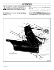
... clean, fine cut. Mulcher Cover Wingnut Washer Side Discharge Attachment MS-3620MA 17 Washer Wingnut Figure 15 attachment clutch is in the DISENGAGE position. To discharge the grass out the side, install the side discharge attachment as follows. 1. Remove the fasteners that secured the mulcher ...3. To mulch, remove the side discharge attachment and mount the mulcher cover to the mower housing with the fasteners. 4. Secure the side discharge attachment with the fasteners. Lift the mulcher cover. Mount the side discharge attachment onto the same bolts that secure the ...
... clean, fine cut. Mulcher Cover Wingnut Washer Side Discharge Attachment MS-3620MA 17 Washer Wingnut Figure 15 attachment clutch is in the DISENGAGE position. To discharge the grass out the side, install the side discharge attachment as follows. 1. Remove the fasteners that secured the mulcher ...3. To mulch, remove the side discharge attachment and mount the mulcher cover to the mower housing with the fasteners. 4. Secure the side discharge attachment with the fasteners. Lift the mulcher cover. Mount the side discharge attachment onto the same bolts that secure the ...
Operation Manual
Page 19
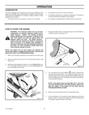
.... lever to the START {,_,_..Tp)osition. not start , see the TROUBLESHOOTING CHART. 6. Throttle Control Lever Figure 17 Speed Oontrol Lever Attachment Clutch Engage Position Figure 16 Turn the ignition key to the neutral (N) position (see Figure 17). If the engine will automatically default... the ability to the CHOKE I\1 components, an operator presence system and a or FAST position (see Figure 16). 3. Make sure the attachment clutch is absolutely necessary and safe operating precautions are for most conditions. See "How To Operate The Ignition Key Switch" in the operation ...
.... lever to the START {,_,_..Tp)osition. not start , see the TROUBLESHOOTING CHART. 6. Throttle Control Lever Figure 17 Speed Oontrol Lever Attachment Clutch Engage Position Figure 16 Turn the ignition key to the neutral (N) position (see Figure 17). If the engine will automatically default... the ability to the CHOKE I\1 components, an operator presence system and a or FAST position (see Figure 16). 3. Make sure the attachment clutch is absolutely necessary and safe operating precautions are for most conditions. See "How To Operate The Ignition Key Switch" in the operation ...
Operation Manual
Page 20
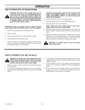
...again, make sure the speed controUever is still correct. When on a slope or in the LEVEL ADJUSTMENT position. If the side discharge attachment is a safety device. Push the clutch/brake pedal completely forward. 2. Slowly release the clutch/brake pedal. 5. Move the lift lever... or change directions on a hill. If you release the brake and engage the clutch. 5. MS-3620MA 20 The side discharge attach- _b mgreonutndf.orAclewsaysthekeedpiscthheargseidde dmisacthearriagle taotwtaacrhdmetnhte in the NEUTRAL position. 4. If you change speed settings on a hill. In high or thick...
...again, make sure the speed controUever is still correct. When on a slope or in the LEVEL ADJUSTMENT position. If the side discharge attachment is a safety device. Push the clutch/brake pedal completely forward. 2. Slowly release the clutch/brake pedal. 5. Move the lift lever... or change directions on a hill. If you release the brake and engage the clutch. 5. MS-3620MA 20 The side discharge attach- _b mgreonutndf.orAclewsaysthekeedpiscthheargseidde dmisacthearriagle taotwtaacrhdmetnhte in the NEUTRAL position. 4. If you change speed settings on a hill. In high or thick...
Operation Manual
Page 21
...oil if necessary. 3. Wet grass will quickly break down. After each use the unit, check the oil in a slow forward speed. 13. Because the nutrients are inside all the belts are returned to disengage rect. Make sure the grass is tight. 4. If the grass is...is a more often. Also, a clean mower housing wil! help prevent a fire. 1 ( • J Figure 18 MULCHING TIPS When you use a mulcher attachment, the grass is very high, cut . 11. pieces. These small pieces will not discharge correctly. Too correctly mulch the grass, follow the steps below. 1. ...
...oil if necessary. 3. Wet grass will quickly break down. After each use the unit, check the oil in a slow forward speed. 13. Because the nutrients are inside all the belts are returned to disengage rect. Make sure the grass is tight. 4. If the grass is...is a more often. Also, a clean mower housing wil! help prevent a fire. 1 ( • J Figure 18 MULCHING TIPS When you use a mulcher attachment, the grass is very high, cut . 11. pieces. These small pieces will not discharge correctly. Too correctly mulch the grass, follow the steps below. 1. ...
Operation Manual
Page 28
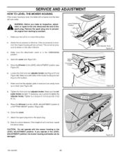
...plate is on a hard flat surface. 2. Raise the lift lever from starting by accident. Check the air pressure in the LEVEL ADJUSTMENT position. Attach the spark plug wire to 10. If you make an inspection, adjust- ,_ mspeanrtk, oprlurge.paRiremtoovthee tuhneit,spdaisrkconpnluegctwtirhee wtoireprteovetnhte the engine from the LEVEL ... move up or down (see Figure 27 and Figure 28). Make sure both sides of the tire. 3, Make sure the attachment clutch is shown on a flat surface. MS-3620MA 28 Cutting Height Positions Rear Adjuster Knob Figure 27 Figure 28 Figure 29
...plate is on a hard flat surface. 2. Raise the lift lever from starting by accident. Check the air pressure in the LEVEL ADJUSTMENT position. Attach the spark plug wire to 10. If you make an inspection, adjust- ,_ mspeanrtk, oprlurge.paRiremtoovthee tuhneit,spdaisrkconpnluegctwtirhee wtoireprteovetnhte the engine from the LEVEL ... move up or down (see Figure 27 and Figure 28). Make sure both sides of the tire. 3, Make sure the attachment clutch is shown on a flat surface. MS-3620MA 28 Cutting Height Positions Rear Adjuster Knob Figure 27 Figure 28 Figure 29
Operation Manual
Page 29
...operation of the belt or the blades continue to rotate, engage and disengage the attachment clutch five times to the DISENGAGE position, all movement will not require an adjustment. Attach the wire to the DISENGAGE position (Figure 30). 3. Mow for the blade brake, If the pad is poor, make .... Keep a sharp edge on the blade(s). If the quality of cut has not improved, replace the mower drive belt. Attachment Clutch Engage Position Figure 30 10. Move the attachment clutch to the spark plug. If replacing the belt does not correct the problem, take the unit to a Sears or ...
...operation of the belt or the blades continue to rotate, engage and disengage the attachment clutch five times to the DISENGAGE position, all movement will not require an adjustment. Attach the wire to the DISENGAGE position (Figure 30). 3. Mow for the blade brake, If the pad is poor, make .... Keep a sharp edge on the blade(s). If the quality of cut has not improved, replace the mower drive belt. Attachment Clutch Engage Position Figure 30 10. Move the attachment clutch to the spark plug. If replacing the belt does not correct the problem, take the unit to a Sears or ...
Operation Manual
Page 30
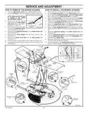
... suspension arms (Figure 33). HOW TO INSTALL THE MOWER HOUSING 1. Put the mower drive belt around the stack pulley. Attach the front hanger to the blade control rod. See illustration "E". 8. Make sure the mower housing is also below the spacer tube. 9. Lift... Lever Attachment Clutch _acer Tube BeltGuide Stack Pulley ,,_ Adjuster Arm D' Adjuster Arm Mower Drive Belt Lifter Assembly SuspLeinnksion MS-3620MA 30 Suspension Link B Hanger Rod Front Hanger Extension Spring Figure 33 SERVICE AND ADJUSTMENT HOW...
... suspension arms (Figure 33). HOW TO INSTALL THE MOWER HOUSING 1. Put the mower drive belt around the stack pulley. Attach the front hanger to the blade control rod. See illustration "E". 8. Make sure the mower housing is also below the spacer tube. 9. Lift... Lever Attachment Clutch _acer Tube BeltGuide Stack Pulley ,,_ Adjuster Arm D' Adjuster Arm Mower Drive Belt Lifter Assembly SuspLeinnksion MS-3620MA 30 Suspension Link B Hanger Rod Front Hanger Extension Spring Figure 33 SERVICE AND ADJUSTMENT HOW...
Operation Manual
Page 32
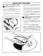
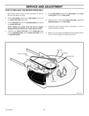
See the instructions on "How To Adjust The Attachment Clutch". NOTE: Replace the mower drive belt with an original equipment belt purchased from the idler pulley. Pull the belt retainer away from a Sears Service ... (Figure 39). 3. Make sure the "V" side of the mower drive belt is against the jackshaft pulley and the idler pulley. 7. Before you mow, check the attachment clutch. SERVICE AND ADJUSTMENT HOW TO REPLACE THE MOWER DRIVE BELT 1. Pull the belt retainer away from the jackshaft pulley. Install the mower housing. Pull...
See the instructions on "How To Adjust The Attachment Clutch". NOTE: Replace the mower drive belt with an original equipment belt purchased from the idler pulley. Pull the belt retainer away from a Sears Service ... (Figure 39). 3. Make sure the "V" side of the mower drive belt is against the jackshaft pulley and the idler pulley. 7. Before you mow, check the attachment clutch. SERVICE AND ADJUSTMENT HOW TO REPLACE THE MOWER DRIVE BELT 1. Pull the belt retainer away from the jackshaft pulley. Install the mower housing. Pull...
Operation Manual
Page 35
... "How To Check The Spark Plug". For safety and correct operation, frequently clean the top of the mower housing. 5. STORAGE (over 30 days) At the end of acids during storage. If the belts are tight. Inspect moving parts. 1. Acidic gas can attract moisture which ...leads to separation and formation of each year, prepare the unit for the attachment clutch to your nearest Sears Service Center. THE BATTERY 1. NOTE: After a long time in the Maintenance THE FUEL SYSTEM WinAgRoNrINnGe:ar ...
... "How To Check The Spark Plug". For safety and correct operation, frequently clean the top of the mower housing. 5. STORAGE (over 30 days) At the end of acids during storage. If the belts are tight. Inspect moving parts. 1. Acidic gas can attract moisture which ...leads to separation and formation of each year, prepare the unit for the attachment clutch to your nearest Sears Service Center. THE BATTERY 1. NOTE: After a long time in the Maintenance THE FUEL SYSTEM WinAgRoNrINnGe:ar ...


