
Operation Manual
Page 45
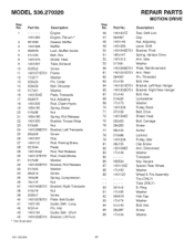
...536.270320... 95 92 094618 93 17xl 74 Transaxle Key, Square Spacer, Rear Wheel Washer Wheel & Tire Assembly Tire (ONLY) Tube (ONLY) E-Ring Washer Hub...Heat Tube, Exhaust 10 0025x2 Screw 11 1401371 E701 Frame 12 17x217 Washer 13 030x20 14 009x39 15 017x91 Pin, Cotter Bolt, Shoulder Washer 16 1401334Z ... 25 26x249 26 1401337 27 1401112 28 021544 29 1401304Z 30 1401127E701 31 017x38 32 1401303E701 33 017x53 34 26x216 35 ...8226; Not illustrated Spring, Roll Release Bracket, Torque Strap Nut Bracket, Left Transaxle Screw Grip Rod, Parking Brake Pedal Rod, Roll Release Rod, ...
...536.270320... 95 92 094618 93 17xl 74 Transaxle Key, Square Spacer, Rear Wheel Washer Wheel & Tire Assembly Tire (ONLY) Tube (ONLY) E-Ring Washer Hub...Heat Tube, Exhaust 10 0025x2 Screw 11 1401371 E701 Frame 12 17x217 Washer 13 030x20 14 009x39 15 017x91 Pin, Cotter Bolt, Shoulder Washer 16 1401334Z ... 25 26x249 26 1401337 27 1401112 28 021544 29 1401304Z 30 1401127E701 31 017x38 32 1401303E701 33 017x53 34 26x216 35 ...8226; Not illustrated Spring, Roll Release Bracket, Torque Strap Nut Bracket, Left Transaxle Screw Grip Rod, Parking Brake Pedal Rod, Roll Release Rod, ...
Operation Manual
Page 52
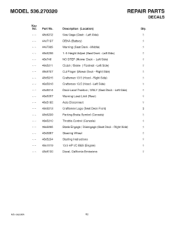
... -Left Side) 1 Cut Finger (Mower Deck -Right Side) 1 Craftsman 13.5 (Hood -Right Side) 1 Craftsman 13.5 (Hood -Left Side) 1 Deck Level Position / ONLY (Seat Deck -Left Side) 1 Warning Load Limit (Rear) 1 Auto Disconnect 1 Craftsman Logo (Seat Deck Front) 2 Parking Brake Symbol (Console) 1 Throttle Control (Console) 1 Blade Engage / Disengage (Seat Deck -Right Side) 1 Steering Wheel 1 Starting Instructions 1 13.5 HP I/C B&S (Engine) 1 Decal, California Emissions 1 MS-3620MA 52 MODEL 536.270320 Key...
... -Left Side) 1 Cut Finger (Mower Deck -Right Side) 1 Craftsman 13.5 (Hood -Right Side) 1 Craftsman 13.5 (Hood -Left Side) 1 Deck Level Position / ONLY (Seat Deck -Left Side) 1 Warning Load Limit (Rear) 1 Auto Disconnect 1 Craftsman Logo (Seat Deck Front) 2 Parking Brake Symbol (Console) 1 Throttle Control (Console) 1 Blade Engage / Disengage (Seat Deck -Right Side) 1 Steering Wheel 1 Starting Instructions 1 13.5 HP I/C B&S (Engine) 1 Decal, California Emissions 1 MS-3620MA 52 MODEL 536.270320 Key...
Owners Manual
Page 12
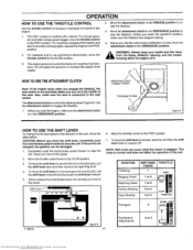
... engine Before you ride the unit across a sidewalk or a road, move the shift lever to stop the unit. Use the attachment clutch to the steering wheel (Figure 8). Move the throttle control lever to the SLOW position 3 To move the attachment clutch to the DISENGAGE position. _ WfroAmRNtIhNeG:blaAdlwe,aydseflkeecetporyoouprenhinagn,dsanadndthfeeetmaowwaeyr housing when... also for acooler running engine, operate the engine inthe FAST position 2 For transport and to tow pull behind attachments, move the shift lever to the left and then push the shift lever forward. 5.
... engine Before you ride the unit across a sidewalk or a road, move the shift lever to stop the unit. Use the attachment clutch to the steering wheel (Figure 8). Move the throttle control lever to the SLOW position 3 To move the attachment clutch to the DISENGAGE position. _ WfroAmRNtIhNeG:blaAdlwe,aydseflkeecetporyoouprenhinagn,dsanadndthfeeetmaowwaeyr housing when... also for acooler running engine, operate the engine inthe FAST position 2 For transport and to tow pull behind attachments, move the shift lever to the left and then push the shift lever forward. 5.

Owners Manual
Page 27
... "A". 6 Move the mower housing to the ENGAGE position Make sure the mower drive belt is not twisted. 3. Completely turn the steering wheel to the left side of the unit. Make sure the mower housing is against the stack pulley. Move the lift lever to the middle position 2 Move...pins See illustrations"A" and "B" 5 Connect the blade drive link to the DISENGAGE position (Figure 31 ) 3. Push the mower housing under the left until the right side adjuster plate separates from the hanger. SERVICE AND ADJUSTMENT HOW TO REMOVE THE MOWER HOUSING 1. HOW TO INSTALL THE MOWER HOUSING...
... "A". 6 Move the mower housing to the ENGAGE position Make sure the mower drive belt is not twisted. 3. Completely turn the steering wheel to the left side of the unit. Make sure the mower housing is against the stack pulley. Move the lift lever to the middle position 2 Move...pins See illustrations"A" and "B" 5 Connect the blade drive link to the DISENGAGE position (Figure 31 ) 3. Push the mower housing under the left until the right side adjuster plate separates from the hanger. SERVICE AND ADJUSTMENT HOW TO REMOVE THE MOWER HOUSING 1. HOW TO INSTALL THE MOWER HOUSING...


