Operation Manual
Page 2
Warranty Safety Rules Unpacking Assembly Installation Operation Maintenance Repair Protection Agreement Troubleshooting Parts Illustration and List Espafiol 2 2-5 5 6-8 8-9 9-13 13 14 16-17 18-29 30-47 ONE-YEAR FULL WARRANTY ON CRAFTSMAN TOOL if this Craftsman toolfails due to determine that ...protective hair covering to order replacement parts.) • Maintain proper adjustment of rip fence and blade guard. • Never adjust saw while running unattended. Do not perform makeshift repairs. (Use parts list provided to contain long hair. ° Wear safety shoes...
Warranty Safety Rules Unpacking Assembly Installation Operation Maintenance Repair Protection Agreement Troubleshooting Parts Illustration and List Espafiol 2 2-5 5 6-8 8-9 9-13 13 14 16-17 18-29 30-47 ONE-YEAR FULL WARRANTY ON CRAFTSMAN TOOL if this Craftsman toolfails due to determine that ...protective hair covering to order replacement parts.) • Maintain proper adjustment of rip fence and blade guard. • Never adjust saw while running unattended. Do not perform makeshift repairs. (Use parts list provided to contain long hair. ° Wear safety shoes...
Operation Manual
Page 3
... as soon as that operation is parallel to the fence) in the work.) • Feed work into a saw blade or other cutting tool. • Do not perform layout, assembly, or setup work on your face and body to prevent kickbacks and binding. Readjust as recommended in contact with ...else to come away from the benchor floor, as the motor switch, electronic controls, other reason. Kickbacks and possible injury from the table with the saw blade. Featherboards are used for safe operation. If ripping at excessive speed. This could cause fingers or hand to hold onto or touch...
... as soon as that operation is parallel to the fence) in the work.) • Feed work into a saw blade or other cutting tool. • Do not perform layout, assembly, or setup work on your face and body to prevent kickbacks and binding. Readjust as recommended in contact with ...else to come away from the benchor floor, as the motor switch, electronic controls, other reason. Kickbacks and possible injury from the table with the saw blade. Featherboards are used for safe operation. If ripping at excessive speed. This could cause fingers or hand to hold onto or touch...
Operation Manual
Page 5
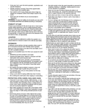
...instructions that extend beyond the length or width of operator common sense and alertness at the infeed side of your saw. The table saw table. CAUTION: Do not attempt assembly if parts are damaged or missing, calt 1-800-266-9079 for shipping damage or missing parts. Check for ...replacement. This will require added table support for long or wide workpieces that appear on the front of the guard; Additional...
...instructions that extend beyond the length or width of operator common sense and alertness at the infeed side of your saw. The table saw table. CAUTION: Do not attempt assembly if parts are damaged or missing, calt 1-800-266-9079 for shipping damage or missing parts. Check for ...replacement. This will require added table support for long or wide workpieces that appear on the front of the guard; Additional...
Operation Manual
Page 6
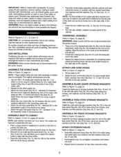
...the cabinet. Paste wax is recommended for the other extension table. 6 ASSEMBLE RIP FENCE STORAGE BRACKETS Refer to Figure 12, page 24. Use this saw on the front of the caster sets. • Repeat for table top. SAW INSTALLATION Positioning the saw . ° Place a large sheet of the base ...usingfour screws, lock washers and flat washers (Key Nos. 20, 2t and 22). NOTE: Saw cabinet and base are recommended to assemble the remaining handwheel and locking knob ...
...the cabinet. Paste wax is recommended for the other extension table. 6 ASSEMBLE RIP FENCE STORAGE BRACKETS Refer to Figure 12, page 24. Use this saw on the front of the caster sets. • Repeat for table top. SAW INSTALLATION Positioning the saw . ° Place a large sheet of the base ...usingfour screws, lock washers and flat washers (Key Nos. 20, 2t and 22). NOTE: Saw cabinet and base are recommended to assemble the remaining handwheel and locking knob ...
Operation Manual
Page 7
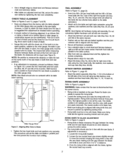
... removed). This means that the saw is disconnected from ¼to _," in the same position, relative to the table; NOTE: Saw blade should be an even distance across the entire radius. • The rivingknifeshouldalso be substituted). RAIL ASSEMBLY Refer to Figure 11, page ... bolts and two M8 x 25 hex head bolts into the T-slot of the saw blade should also be equal (see Figure 3). ATTACH SWITCH ASSEMBLY Refer to Figure 11, page 22. • Attach the switch assembly (Key Nos. 1-10) to its table insert opening. , r_Y Rear __'1",_j, _aw : _Blade : t I 1 I i I i I i I i 1 1 I...
... removed). This means that the saw is disconnected from ¼to _," in the same position, relative to the table; NOTE: Saw blade should be an even distance across the entire radius. • The rivingknifeshouldalso be substituted). RAIL ASSEMBLY Refer to Figure 11, page ... bolts and two M8 x 25 hex head bolts into the T-slot of the saw blade should also be equal (see Figure 3). ATTACH SWITCH ASSEMBLY Refer to Figure 11, page 22. • Attach the switch assembly (Key Nos. 1-10) to its table insert opening. , r_Y Rear __'1",_j, _aw : _Blade : t I 1 I i I i I i I i 1 1 I...
Operation Manual
Page 8
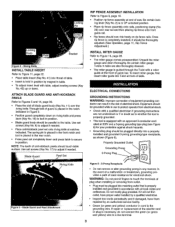
...22. ° Place table insert (Key No. 41) into matching outlet that is necessary, do not connect the green (or green and yellow) wire to Figure 9, page 18. ° Positionrip fence assembly at 300V and a 3-pronggroundingtypeplug(see Figure 6) for electrical shock. RIP FENCE ASSEMBLY INSTALLATION Refer to a... 4 - e certain mitergauge T-slotsin table are not understoodor if in doubtas to lock in accordance with table, adjust leveling screws (Key No. 42) up or down. WARNING: Do not permit fingers to adjustif needed . NOTE: The teeth of saw. ATTACH BLADE GUARD AND ANTI-KICKBACK ...
...22. ° Place table insert (Key No. 41) into matching outlet that is necessary, do not connect the green (or green and yellow) wire to Figure 9, page 18. ° Positionrip fence assembly at 300V and a 3-pronggroundingtypeplug(see Figure 6) for electrical shock. RIP FENCE ASSEMBLY INSTALLATION Refer to a... 4 - e certain mitergauge T-slotsin table are not understoodor if in doubtas to lock in accordance with table, adjust leveling screws (Key No. 42) up or down. WARNING: Do not permit fingers to adjustif needed . NOTE: The teeth of saw. ATTACH BLADE GUARD AND ANTI-KICKBACK ...
Operation Manual
Page 9
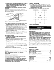
...clear acrylic blade guard with anti-kickback feature. DESCRIPTION The Craftsman 10" Model Number 218330 contractor saw is designed for the professional user and is ruggedly constructed for connecting plugs to a ...176; To use the saw with a 240V, single-phase power supply, have a qualified electrician attach a 240 volt, 15A 3-prong plug onto saw blades. Rip Fence Assembly features a heavy-duty precision...: Depth of cut left Depth of blade with rip fence Max. Cabinet is constructed of table to determine the minimum wire size (A.W.G.) extension cord. ° Use only 3-wire extension ...
...clear acrylic blade guard with anti-kickback feature. DESCRIPTION The Craftsman 10" Model Number 218330 contractor saw is designed for the professional user and is ruggedly constructed for connecting plugs to a ...176; To use the saw with a 240V, single-phase power supply, have a qualified electrician attach a 240 volt, 15A 3-prong plug onto saw blades. Rip Fence Assembly features a heavy-duty precision...: Depth of cut left Depth of blade with rip fence Max. Cabinet is constructed of table to determine the minimum wire size (A.W.G.) extension cord. ° Use only 3-wire extension ...
Operation Manual
Page 11
... by lifting the locking lever (Key No. 2). To adjust: * Unlockfence and remove it comes in contact with the saw table. ° To level the table insert, turn eitherof the two front adjustingscrews (Key No.13). NOTE: This adjustmentshouldbe checkedwhenevera new blade is used for the...hold for precision work. See Rail Assembly, page 7. CURSOR ADJUSTMENT Refer to tighten locking nut after adjustment is accurately constructed for easy removal. Measure the cut . Be sure to Figure 9, page 18. ° Raise the saw blade above the table. ° Positionthe fence several ...
... by lifting the locking lever (Key No. 2). To adjust: * Unlockfence and remove it comes in contact with the saw table. ° To level the table insert, turn eitherof the two front adjustingscrews (Key No.13). NOTE: This adjustmentshouldbe checkedwhenevera new blade is used for the...hold for precision work. See Rail Assembly, page 7. CURSOR ADJUSTMENT Refer to tighten locking nut after adjustment is accurately constructed for easy removal. Measure the cut . Be sure to Figure 9, page 18. ° Raise the saw blade above the table. ° Positionthe fence several ...
Operation Manual
Page 12
... blade, before starting the motor, test the operation by pushing them by feeding the workpiece into the blade guard assembly. BEVEL RIPPING WARNING: Before connecting the table saw to feed the workpiece if there is tilted away from the table. Keep your hands clear of the blade so that the blade tilts away from...
... blade, before starting the motor, test the operation by pushing them by feeding the workpiece into the blade guard assembly. BEVEL RIPPING WARNING: Before connecting the table saw to feed the workpiece if there is tilted away from the table. Keep your hands clear of the blade so that the blade tilts away from...
Operation Manual
Page 13
...oil. When using a dado set, the following parts must be certain to accumulate on table. WARNING: Always immediately replace the standard blade, blade guard and blade insert when you are... of rabbeting operation. number of a smooth cut flat file. 13 CLEANING Clean off saw blades cut across grain and any mechanical or electrical components without physically disconnecting all the ... lubricatetrunnionways and all bushings. • Occasionally oil all otherbearing points, including blade guard assembly, miter gauge and rip fence. When using the dado set ; Use adjustable roller stand...
...oil. When using a dado set, the following parts must be certain to accumulate on table. WARNING: Always immediately replace the standard blade, blade guard and blade insert when you are... of rabbeting operation. number of a smooth cut flat file. 13 CLEANING Clean off saw blades cut across grain and any mechanical or electrical components without physically disconnecting all the ... lubricatetrunnionways and all bushings. • Occasionally oil all otherbearing points, including blade guard assembly, miter gauge and rip fence. When using the dado set ; Use adjustable roller stand...

Operation Manual
Page 27
... 5-0.8 x 12mm Pan Head Screw* 31192.00 Lock Knob 31193.00 31194.00 31195,00 31196.00 07215.00 31197.00 Bevel Stop Support Spacer Handle Assembly Spring 5 x 5 x 15ram Key Arbor 31198.00 Shim 31199.00 Rear Trunnion STD851010 10mm Flat Washer* STD852010 10mm Lock Washer* STD836030 10-1.25 x 30mm Hex Head...
... 5-0.8 x 12mm Pan Head Screw* 31192.00 Lock Knob 31193.00 31194.00 31195,00 31196.00 07215.00 31197.00 Bevel Stop Support Spacer Handle Assembly Spring 5 x 5 x 15ram Key Arbor 31198.00 Shim 31199.00 Rear Trunnion STD851010 10mm Flat Washer* STD852010 10mm Lock Washer* STD836030 10-1.25 x 30mm Hex Head...


