
Limited Warranty and Technical Support
Page 1
... will not alter form, fit, or function of the product 1 LIMITED WARRANTY AND TECHNICAL SUPPORT Your HP Limited Warranty consists of the repair or replacement of defective parts, including hard drives identified by HP Intelligent Manageability software as "HP") with "1 YR," "2 YR," or "3 YR" marked on... the serial number label located on the back of the unit Included HP accessories, digital writing pen, and batteries Duration of Warranty Period 1 year, 2 years, or 3 years, according to the serial number label 1 Year Non-HP accessories Not warranted by or ...
... will not alter form, fit, or function of the product 1 LIMITED WARRANTY AND TECHNICAL SUPPORT Your HP Limited Warranty consists of the repair or replacement of defective parts, including hard drives identified by HP Intelligent Manageability software as "HP") with "1 YR," "2 YR," or "3 YR" marked on... the serial number label located on the back of the unit Included HP accessories, digital writing pen, and batteries Duration of Warranty Period 1 year, 2 years, or 3 years, according to the serial number label 1 Year Non-HP accessories Not warranted by or ...
Hardware Guide
Page 15
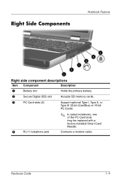
Right Side Components Notebook Features Right side component descriptions Item Component Description 1 Battery slot Holds the primary battery. 2 Secure Digital (SD) slot Accepts SD memory cards. 3 PC Card slots (2) Support optional Type I, Type II, or Type III 32-bit (CardBus) or 16-bit PC Cards. 4 RJ-11 telephone jack ✎ In select notebooks, one of the PC Card slots may be replaced with a factory-installed Smart Card Reader. Connects a modem cable. Hardware Guide 1-9
Right Side Components Notebook Features Right side component descriptions Item Component Description 1 Battery slot Holds the primary battery. 2 Secure Digital (SD) slot Accepts SD memory cards. 3 PC Card slots (2) Support optional Type I, Type II, or Type III 32-bit (CardBus) or 16-bit PC Cards. 4 RJ-11 telephone jack ✎ In select notebooks, one of the PC Card slots may be replaced with a factory-installed Smart Card Reader. Connects a modem cable. Hardware Guide 1-9
Hardware Guide
Page 101
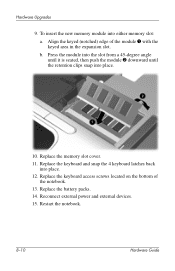
...in the expansion slot. To insert the new memory module into place. 12. Replace the memory slot cover. 11. Replace the keyboard and snap the 4 keyboard latches back into either memory slot: a. Replace the battery packs. 14. Reconnect external power and external devices. 15. Press the module... into the slot from a 45-degree angle until it is seated, then push the module 2 downward until the retention clips snap into place. 10. b. Hardware Upgrades 9. Restart the notebook. 8-10 ...
...in the expansion slot. To insert the new memory module into place. 12. Replace the memory slot cover. 11. Replace the keyboard and snap the 4 keyboard latches back into either memory slot: a. Replace the battery packs. 14. Reconnect external power and external devices. 15. Press the module... into the slot from a 45-degree angle until it is seated, then push the module 2 downward until the retention clips snap into place. 10. b. Hardware Upgrades 9. Restart the notebook. 8-10 ...

Hardware Guide
Page 107
...PC Card 8-2 digital vs. See battery bay; MultiBay Bluetooth 2-9 buttons mute 2-9, 5-1 PC Card 8-3 pointing stick 2-1 power 1-3 Presentation Mode 2-9 Quick Launch 1-4, 2-9 Quick Lock 2-9 TouchPad 2-1 volume control 5-1 Wireless On/Off 2-9 C cable lock 7-6 cables modem 6-1, 6-2 network 6-4 security 7-6 calibration, battery 3-13 cap, replacing... pointing stick 2-3 caps lock light 1-6 card and socket services, PC Card 8-2 CD displaying contents 4-16 inserting 4-13 removing 4-15 CD drive ...
...PC Card 8-2 digital vs. See battery bay; MultiBay Bluetooth 2-9 buttons mute 2-9, 5-1 PC Card 8-3 pointing stick 2-1 power 1-3 Presentation Mode 2-9 Quick Launch 1-4, 2-9 Quick Lock 2-9 TouchPad 2-1 volume control 5-1 Wireless On/Off 2-9 C cable lock 7-6 cables modem 6-1, 6-2 network 6-4 security 7-6 calibration, battery 3-13 cap, replacing... pointing stick 2-3 caps lock light 1-6 card and socket services, PC Card 8-2 CD displaying contents 4-16 inserting 4-13 removing 4-15 CD drive ...

Hardware Guide
Page 111
...I, II, III 8-1 zoomed video 8-1 PC Card slots 1-9 peripherals, connecting and disconnecting 7-1 pointing device (dual pointing stick/TouchPad models) 1-2 pointing device (TouchPad models) 1-1 pointing device preferences 2-4 pointing stick buttons 2-1 cap, replacing 2-3 location 2-1 using 2-3 Port Replicator ...docking connecter 1-15 external device connections 2-4 port, infrared 6-5 power rated input 9-3 switching between AC and battery 3-1 See also battery power power button 1-3 power connector 1-...
...I, II, III 8-1 zoomed video 8-1 PC Card slots 1-9 peripherals, connecting and disconnecting 7-1 pointing device (dual pointing stick/TouchPad models) 1-2 pointing device (TouchPad models) 1-1 pointing device preferences 2-4 pointing stick buttons 2-1 cap, replacing 2-3 location 2-1 using 2-3 Port Replicator ...docking connecter 1-15 external device connections 2-4 port, infrared 6-5 power rated input 9-3 switching between AC and battery 3-1 See also battery power power button 1-3 power connector 1-...

Software Guide
Page 78
...Changes and Exit, then follow the instructions on the screen. Replace configuration settings in the system. ■ View specification information about the notebook and any identification information you save are restored, and any battery packs in Computer Setup with factory default settings. (Identification information...retained.) Cancel changes entered during the current session, then exit and restart the notebook. When the computer restarts, the factory settings are in effect when the notebook restarts. Save changes entered during the current session, then exit and restart ...
...Changes and Exit, then follow the instructions on the screen. Replace configuration settings in the system. ■ View specification information about the notebook and any identification information you save are restored, and any battery packs in Computer Setup with factory default settings. (Identification information...retained.) Cancel changes entered during the current session, then exit and restart the notebook. When the computer restarts, the factory settings are in effect when the notebook restarts. Save changes entered during the current session, then exit and restart ...
Getting Started
Page 17
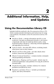
..., including details about modem connections and equipment. I Hardware Guide-contains information specific to all exterior components and steps for replacing battery packs, using keyboard features and drives, connecting external equipment, and upgrading the notebook. Startup Guide 2-1 Documents on the Documentation Library CD include: I Regulatory and Safety Notices-includes governmental agency and safety information...
..., including details about modem connections and equipment. I Hardware Guide-contains information specific to all exterior components and steps for replacing battery packs, using keyboard features and drives, connecting external equipment, and upgrading the notebook. Startup Guide 2-1 Documents on the Documentation Library CD include: I Regulatory and Safety Notices-includes governmental agency and safety information...

Getting Started
Page 31
334088-001.book Page 9 Friday, July 11, 2003 3:39 PM Right Side Components Notebook Features Right side component descriptions Item Component Description 1 Battery slot Holds the primary battery. 2 Secure Digital (SD) slot Accepts SD memory cards. 3 PC Card slots (2) Support optional Type I, Type II, or Type III 32-bit (CardBus) or 16-bit PC Cards. ✎ In select notebooks, one of the PC Card slots may be replaced with a factory-installed Smart Card Reader. 4 RJ-11 telephone jack Connects a modem cable. Startup Guide 3-9
334088-001.book Page 9 Friday, July 11, 2003 3:39 PM Right Side Components Notebook Features Right side component descriptions Item Component Description 1 Battery slot Holds the primary battery. 2 Secure Digital (SD) slot Accepts SD memory cards. 3 PC Card slots (2) Support optional Type I, Type II, or Type III 32-bit (CardBus) or 16-bit PC Cards. ✎ In select notebooks, one of the PC Card slots may be replaced with a factory-installed Smart Card Reader. 4 RJ-11 telephone jack Connects a modem cable. Startup Guide 3-9
Getting Started - Enhanced for Accessibility
Page 17
... on the Documentation Library CD include: ■ Hardware Guide-contains information specific to all exterior components and steps for replacing battery packs, using keyboard features and drives, connecting external equipment, and upgrading the notebook. ■ Software Guide-describes HP software, including details about power and security features. ■ Modem and Networking guide-provides...
... on the Documentation Library CD include: ■ Hardware Guide-contains information specific to all exterior components and steps for replacing battery packs, using keyboard features and drives, connecting external equipment, and upgrading the notebook. ■ Software Guide-describes HP software, including details about power and security features. ■ Modem and Networking guide-provides...

Getting Started - Enhanced for Accessibility
Page 31
Right Side Components Notebook Features Right side component descriptions Item Component Description 1 Battery slot Holds the primary battery. 2 Secure Digital (SD) slot Accepts SD memory cards. 3 PC Card slots (2) Support optional Type I, Type II, or Type III 32-bit (CardBus) or 16-bit PC Cards. ✎ In select notebooks, one of the PC Card slots may be replaced with a factory-installed Smart Card Reader. 4 RJ-11 telephone jack Connects a modem cable. Startup Guide 3-9
Right Side Components Notebook Features Right side component descriptions Item Component Description 1 Battery slot Holds the primary battery. 2 Secure Digital (SD) slot Accepts SD memory cards. 3 PC Card slots (2) Support optional Type I, Type II, or Type III 32-bit (CardBus) or 16-bit PC Cards. ✎ In select notebooks, one of the PC Card slots may be replaced with a factory-installed Smart Card Reader. 4 RJ-11 telephone jack Connects a modem cable. Startup Guide 3-9

HP Compaq nc6000 Notebook PC - Maintenance and Service Guide
Page 5
Contents 5 Removal and Replacement Procedures 5.1 Serial Number 5-2 5.2 Disassembly Sequence Chart 5-3 5.3 Preparing the Notebook for Disassembly 5-5 5.4 Notebook Feet 5-11 5.5 Mini PCI Communications Board 5-12 5.6 MultiBay Device 5-16 5.7 Bluetooth Wireless Communications Board. . . . . . 5-17 5.8 Integrated Smart Card 5-19 5.9 Keyboard 5-21 5.10... 5.15 Fan Assembly 5-32 5.16 Heat Sink 5-35 5.17 Processor 5-38 5.18 Display Assembly 5-40 5.19 Top Cover 5-44 5.20 RTC Battery 5-47 5.21 LED Board 5-49 5.22 Button Board 5-51 5.23 System Board 5-53 Maintenance and Service Guide v
Contents 5 Removal and Replacement Procedures 5.1 Serial Number 5-2 5.2 Disassembly Sequence Chart 5-3 5.3 Preparing the Notebook for Disassembly 5-5 5.4 Notebook Feet 5-11 5.5 Mini PCI Communications Board 5-12 5.6 MultiBay Device 5-16 5.7 Bluetooth Wireless Communications Board. . . . . . 5-17 5.8 Integrated Smart Card 5-19 5.9 Keyboard 5-21 5.10... 5.15 Fan Assembly 5-32 5.16 Heat Sink 5-35 5.17 Processor 5-38 5.18 Display Assembly 5-40 5.19 Top Cover 5-44 5.20 RTC Battery 5-47 5.21 LED Board 5-49 5.22 Button Board 5-51 5.23 System Board 5-53 Maintenance and Service Guide v
HP Compaq nc6000 Notebook PC - Maintenance and Service Guide
Page 19
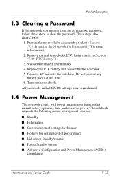
...Replace the RTC battery and reassemble the notebook. 5. Turn on the notebook. Product Description 1.3 Clearing a Password If the notebook you are servicing has an unknown password, follow these steps to Section "5.3 Preparing the Notebook for Disassembly" for more information). 2. Wait approximately five minutes. 4. Do not reinsert any battery... steps also clear CMOS: 1. Remove the real time clock (RTC) battery (refer to the notebook. Connect AC power to Section "5.20 RTC Battery"). 3. The notebook supports the following power management features: ■ Standby ■ Hibernation ...
...Replace the RTC battery and reassemble the notebook. 5. Turn on the notebook. Product Description 1.3 Clearing a Password If the notebook you are servicing has an unknown password, follow these steps to Section "5.3 Preparing the Notebook for Disassembly" for more information). 2. Wait approximately five minutes. 4. Do not reinsert any battery... steps also clear CMOS: 1. Remove the real time clock (RTC) battery (refer to the notebook. Connect AC power to Section "5.20 RTC Battery"). 3. The notebook supports the following power management features: ■ Standby ■ Hibernation ...

HP Compaq nc6000 Notebook PC - Maintenance and Service Guide
Page 32
...power consumption, certain power management/battery conservation configurations, battery fast charging, and some software applications. Product Description 1.6 Design Overview This section presents a design overview of key parts and features of the notebook. The notebook uses an electric fan for ...9632; Keyboard and TouchPad ■ Audio ■ Mobile Intel Pentium 4 Processor-M ■ Fan ■ PC Card Ä CAUTION: To properly ventilate the notebook, allow at least a 7.6-cm (3-inch) clearance on automatically when high temperature conditions exist. These conditions can be...
...power consumption, certain power management/battery conservation configurations, battery fast charging, and some software applications. Product Description 1.6 Design Overview This section presents a design overview of key parts and features of the notebook. The notebook uses an electric fan for ...9632; Keyboard and TouchPad ■ Audio ■ Mobile Intel Pentium 4 Processor-M ■ Fan ■ PC Card Ä CAUTION: To properly ventilate the notebook, allow at least a 7.6-cm (3-inch) clearance on automatically when high temperature conditions exist. These conditions can be...
HP Compaq nc6000 Notebook PC - Maintenance and Service Guide
Page 35
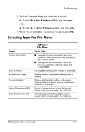
... and Exit Save Changes and Exit Table 2-1 File Menu To Do This ■ View identification information about the notebook, a Port Replicator, and any battery packs in Computer Setup with factory default settings. Cancel changes entered during the current session, then exit and restart the...; Select File > Save Changes and Exit and press enter. - Save changes entered during the current session, then exit and restart the notebook. Replace configuration settings in the system. ■ View specification information about the processor, memory and cache size, and system ROM. or - &#...
... and Exit Save Changes and Exit Table 2-1 File Menu To Do This ■ View identification information about the notebook, a Port Replicator, and any battery packs in Computer Setup with factory default settings. Cancel changes entered during the current session, then exit and restart the...; Select File > Save Changes and Exit and press enter. - Save changes entered during the current session, then exit and restart the notebook. Replace configuration settings in the system. ■ View specification information about the processor, memory and cache size, and system ROM. or - &#...

HP Compaq nc6000 Notebook PC - Maintenance and Service Guide
Page 45
N Power on ? Y Power on ? Flowchart 2.3-No Power, Part 2 Continued from "Flowchart 2.2-No Power, Part 1" Troubleshooting Visually check for debris in battery socket and clean if necessary. Y Go to another notebook, or replacing it to "Flowchart 2.4-No Power, Part 3" Done Maintenance and Service Guide 2-13 Y Replace power supply (if applicable). N Done Power on? N Done Check battery by recharging it, moving it .
N Power on ? Y Power on ? Flowchart 2.3-No Power, Part 2 Continued from "Flowchart 2.2-No Power, Part 1" Troubleshooting Visually check for debris in battery socket and clean if necessary. Y Go to another notebook, or replacing it to "Flowchart 2.4-No Power, Part 3" Done Maintenance and Service Guide 2-13 Y Replace power supply (if applicable). N Done Power on? N Done Check battery by recharging it, moving it .

HP Compaq nc6000 Notebook PC - Maintenance and Service Guide
Page 89
Removal and Replacement Procedures 5.2 Disassembly Sequence Chart Use the chart below to determine the section number to disassemble Notebook feet 0 Mini PCI communications board 1 MultiBay device 0 Bluetooth wireless communications 3 board Integrated smart card...0 Display assembly 4 Top cover 16 RTC battery 0 Maintenance and Service Guide 5-3 Section 5.3 5.4 5.5 5.6 5.7 5.8 5.9 5.10 5.11 5.12 5.13 5.14 5.15 5.16 5.17 5.18 5.19 5.20 Disassembly Sequence Chart Description # of Screws Removed Preparing the notebook for disassembly Battery pack Hard drive 0 2 to remove, ...
Removal and Replacement Procedures 5.2 Disassembly Sequence Chart Use the chart below to determine the section number to disassemble Notebook feet 0 Mini PCI communications board 1 MultiBay device 0 Bluetooth wireless communications 3 board Integrated smart card...0 Display assembly 4 Top cover 16 RTC battery 0 Maintenance and Service Guide 5-3 Section 5.3 5.4 5.5 5.6 5.7 5.8 5.9 5.10 5.11 5.12 5.13 5.14 5.15 5.16 5.17 5.18 5.19 5.20 Disassembly Sequence Chart Description # of Screws Removed Preparing the notebook for disassembly Battery pack Hard drive 0 2 to remove, ...
HP Compaq nc6000 Notebook PC - Maintenance and Service Guide
Page 91
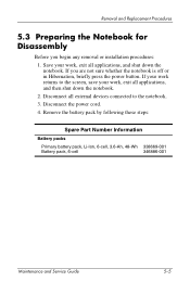
...Replacement Procedures 5.3 Preparing the Notebook for Disassembly Before you are not sure whether the notebook is off or in Hibernation, briefly press the power button. Save your work , exit all applications, and shut down the notebook. 2. Disconnect the power cord. 4. If your work , exit all applications, and then shut down the notebook. Remove the battery... pack by following these steps: Spare Part Number Information Battery packs Primary battery pack, Li-Ion, 6-cell, 3.6-Ah, 48-Wh 338669-001 Battery pack, 6-cell 346886-001 ...
...Replacement Procedures 5.3 Preparing the Notebook for Disassembly Before you are not sure whether the notebook is off or in Hibernation, briefly press the power button. Save your work , exit all applications, and shut down the notebook. 2. Disconnect the power cord. 4. If your work , exit all applications, and then shut down the notebook. Remove the battery... pack by following these steps: Spare Part Number Information Battery packs Primary battery pack, Li-Ion, 6-cell, 3.6-Ah, 48-Wh 338669-001 Battery pack, 6-cell 346886-001 ...

HP Compaq nc6000 Notebook PC - Maintenance and Service Guide
Page 92
c. Slide and hold the battery release latch 1 toward the back of the notebook. b. Use the notch in the battery pack to slide the battery pack to the left 2. d. Remove the battery pack. Removal and Replacement Procedures a. Removing the Battery Pack 5-6 Maintenance and Service Guide Turn the notebook upside down, with the front panel facing you.
c. Slide and hold the battery release latch 1 toward the back of the notebook. b. Use the notch in the battery pack to slide the battery pack to the left 2. d. Remove the battery pack. Removal and Replacement Procedures a. Removing the Battery Pack 5-6 Maintenance and Service Guide Turn the notebook upside down, with the front panel facing you.

HP Compaq nc6000 Notebook PC - Maintenance and Service Guide
Page 93
Removal and Replacement Procedures 5. Remove the battery bezel by sliding it down and off of the battery pack. ✎ The battery bezel is included in the Miscellaneous Plastics Kit, spare part number 344411-001. Removing the Battery Bezel Reverse the above procedure to install the battery pack and battery bezel. Maintenance and Service Guide 5-7
Removal and Replacement Procedures 5. Remove the battery bezel by sliding it down and off of the battery pack. ✎ The battery bezel is included in the Miscellaneous Plastics Kit, spare part number 344411-001. Removing the Battery Bezel Reverse the above procedure to install the battery pack and battery bezel. Maintenance and Service Guide 5-7
HP Compaq nc6000 Notebook PC - Maintenance and Service Guide
Page 102
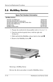
...MultiBay device. 5-16 Maintenance and Service Guide Turn the notebook upside down, with the right side facing you. 3. Removing a MultiBay Device Reverse the above procedure to the right 1. 4. Remove the MultiBay device 2. Removal and Replacement Procedures 5.6 MultiBay Device Spare Part Number Information MultiBay ...devices 24X Max CD-ROM drive 24X Max DVD/CD-RW combo drive 4X Max DVD+RW/R and CD-RW combo drive 8X Max DVD-ROM Drive Diskette drive MultiBay battery pack 100044-001...
...MultiBay device. 5-16 Maintenance and Service Guide Turn the notebook upside down, with the right side facing you. 3. Removing a MultiBay Device Reverse the above procedure to the right 1. 4. Remove the MultiBay device 2. Removal and Replacement Procedures 5.6 MultiBay Device Spare Part Number Information MultiBay ...devices 24X Max CD-ROM drive 24X Max DVD/CD-RW combo drive 4X Max DVD+RW/R and CD-RW combo drive 8X Max DVD-ROM Drive Diskette drive MultiBay battery pack 100044-001...


