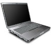
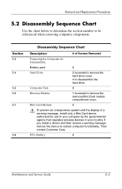
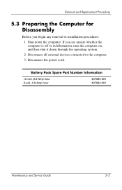
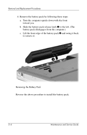
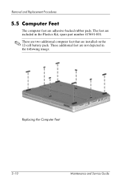
Presario V5000 Battery Replacement - Compaq Notebook PC
Presario V5000 Battery Replacement
View Results Below
Free Compaq Presario V5000 manuals!
Problems with Compaq Presario V5000?
Ask a Question
Free Compaq Presario V5000 manuals!
Problems with Compaq Presario V5000?
Ask a Question
Related Manual Pages


Similar Questions

How Do I Connect Direct Power To My V5000 Without A Battery
i ha e a compaq pasario notebookv5000 dont have a battery but trying to connect power so i can use
i ha e a compaq pasario notebookv5000 dont have a battery but trying to connect power so i can use
(Posted by Anonymous-158503 8 years ago)


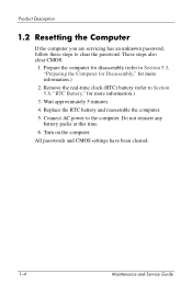
Replacement Cmos Battery Presario 1800
I want to replace CMOS I think it's dead every start I have to put time and date mannualy
I want to replace CMOS I think it's dead every start I have to put time and date mannualy
(Posted by sashacapital 9 years ago)

How To Replace A Wireless Card Presario V5000
(Posted by jenraam 10 years ago)

Which Compartment Is My Cmos Battery In ..it Needs To Be Replaced ,,
(Posted by aggs 11 years ago)