
Maintenance and Service Guide
Page 6
...37 Battery ...38 Memory module ...39 WLAN module ...40 Keyboard ...43 Optical drive ...47 Hard drive ...49 RTC battery ...52 Top cover ...53 Power button board 57 TouchPad button board 58 Optical drive connector cable 61 Speakers ...63 USB board ...65 System board ...67 Fan/heat sink assembly 69 Processor ...71 Display assembly ...73 Power connector cable 82 5 Using Setup Utility (BIOS) and System Diagnostics 84 Starting Setup Utility (BIOS) ...84 Updating the BIOS ...84 Determining the BIOS version 85 Downloading a BIOS update 85 Using System Diagnostics ...86 6 Specifications ...87...
...37 Battery ...38 Memory module ...39 WLAN module ...40 Keyboard ...43 Optical drive ...47 Hard drive ...49 RTC battery ...52 Top cover ...53 Power button board 57 TouchPad button board 58 Optical drive connector cable 61 Speakers ...63 USB board ...65 System board ...67 Fan/heat sink assembly 69 Processor ...71 Display assembly ...73 Power connector cable 82 5 Using Setup Utility (BIOS) and System Diagnostics 84 Starting Setup Utility (BIOS) ...84 Updating the BIOS ...84 Determining the BIOS version 85 Downloading a BIOS update 85 Using System Diagnostics ...86 6 Specifications ...87...

Maintenance and Service Guide
Page 13
...;1536 external resolution @ 75 Hz, hot plug and unplug and autodetection for correct output to 1920×1200 @ 60Hz ● HP Smart AC adapter ● RJ-45 (Ethernet Gigabit support with 2-GB of system memory) ● FreeDOS Compaq Presario CQ58 √ √ √ HP 2000 Notebook PC √ 5 Category Ports Keyboard/pointing devices Power requirements Security Operating system Description ● Audio-in .), textured, pocket keyboard, no...
...;1536 external resolution @ 75 Hz, hot plug and unplug and autodetection for correct output to 1920×1200 @ 60Hz ● HP Smart AC adapter ● RJ-45 (Ethernet Gigabit support with 2-GB of system memory) ● FreeDOS Compaq Presario CQ58 √ √ √ HP 2000 Notebook PC √ 5 Category Ports Keyboard/pointing devices Power requirements Security Operating system Description ● Audio-in .), textured, pocket keyboard, no...
Maintenance and Service Guide
Page 26
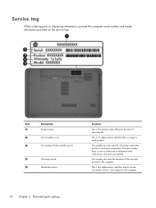
... each product. This is the product name affixed to locate documents, drivers, and support for the computer. Service tag When ordering parts or requesting information, provide the computer serial number and model description provided on the service tag. Item (1) (2) (3) Description Product name Serial number (s/n) Part number/Product number (p/n) (4) Warranty period (5) Model description Function This is the alphanumeric identifier used to the front of the warranty period for the...
... each product. This is the product name affixed to locate documents, drivers, and support for the computer. Service tag When ordering parts or requesting information, provide the computer serial number and model description provided on the service tag. Item (1) (2) (3) Description Product name Serial number (s/n) Part number/Product number (p/n) (4) Warranty period (5) Model description Function This is the alphanumeric identifier used to the front of the warranty period for the...
Maintenance and Service Guide
Page 29
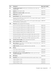
...) (12) (13) (14) (15) (16) (17) Component Spare part number TouchPad button board (includes bracket, TouchPad button board cable, and TouchPad cable) 686271-001 Speakers (include speaker cables) 686279-001 Optical drive connector cable (includes bracket) 686257-001 USB board (includes cable) 686269-001 System board (includes replacement thermal material): Equipped with Intel HM75 Express chipset and for use with computer models equipped 686280-001 with an Intel Core i5 or...
...) (12) (13) (14) (15) (16) (17) Component Spare part number TouchPad button board (includes bracket, TouchPad button board cable, and TouchPad cable) 686271-001 Speakers (include speaker cables) 686279-001 Optical drive connector cable (includes bracket) 686257-001 USB board (includes cable) 686269-001 System board (includes replacement thermal material): Equipped with Intel HM75 Express chipset and for use with computer models equipped 686280-001 with an Intel Core i5 or...

Maintenance and Service Guide
Page 33
Mass storage devices Item (1) (2a) (2b) (3) Component Spare part number Hard drive (does not include hard drive bracket, hard drive connector cable, or screws): 750-GB, 5400-rpm, 9.5-mm 634250-001 640-GB, 5400-rpm, 9.5-mm 669300-001 500-GB, 5400-rpm, 9.5-mm 669299-001 320-GB, 5400-rpm, 9.5-mm 622643-001 Hard Drive Hardware Kit, includes: 686261-001 Hard drive bracket Hard drive connector cable Hard drive bracket screws (not illustrated) DVD±RW Double-Layer with SuperMulti Drive (includes optical drive bezel and optical drive bracket) 686268-001 Mass storage devices 25
Mass storage devices Item (1) (2a) (2b) (3) Component Spare part number Hard drive (does not include hard drive bracket, hard drive connector cable, or screws): 750-GB, 5400-rpm, 9.5-mm 634250-001 640-GB, 5400-rpm, 9.5-mm 669300-001 500-GB, 5400-rpm, 9.5-mm 669299-001 320-GB, 5400-rpm, 9.5-mm 622643-001 Hard Drive Hardware Kit, includes: 686261-001 Hard drive bracket Hard drive connector cable Hard drive bracket screws (not illustrated) DVD±RW Double-Layer with SuperMulti Drive (includes optical drive bezel and optical drive bracket) 686268-001 Mass storage devices 25

Maintenance and Service Guide
Page 57
... all external devices from the computer. 3. Description 750-GB, 5400-rpm, 9.5-mm 640-GB, 5400-rpm, 9.5-mm 500-GB, 5400-rpm, 9.5-mm 320-GB, 5400-rpm, 9.5-mm Hard Drive Hardware Kit (includes hard drive bracket, hard drive connector cable, and screws) Spare part number 634250-001 669300-001 669299-001 622643-001 686261-001 Before removing the hard drive, follow these steps: 1. Remove the memory module/wireless module compartment cover (see Battery...
... all external devices from the computer. 3. Description 750-GB, 5400-rpm, 9.5-mm 640-GB, 5400-rpm, 9.5-mm 500-GB, 5400-rpm, 9.5-mm 320-GB, 5400-rpm, 9.5-mm Hard Drive Hardware Kit (includes hard drive bracket, hard drive connector cable, and screws) Spare part number 634250-001 669300-001 669299-001 622643-001 686261-001 Before removing the hard drive, follow these steps: 1. Remove the memory module/wireless module compartment cover (see Battery...

Maintenance and Service Guide
Page 60
... board. 2. Remove the battery (see Hard drive on page 38). 5. Use a flat-bladed, non-metallic tool (1) to release the RTC battery from the computer. 3. Disconnect all external devices from the computer. 4. Remove the RTC battery (2). 52 Chapter 4 Removal and replacement procedures If you are unsure whether the computer is off the computer. Remove the hard drive compartment cover (see Battery on page 49). Remove the RTC battery: 1. Remove the memory module/wireless module compartment cover (see Memory module...
... board. 2. Remove the battery (see Hard drive on page 38). 5. Use a flat-bladed, non-metallic tool (1) to release the RTC battery from the computer. 3. Disconnect all external devices from the computer. 4. Remove the RTC battery (2). 52 Chapter 4 Removal and replacement procedures If you are unsure whether the computer is off the computer. Remove the hard drive compartment cover (see Battery on page 49). Remove the RTC battery: 1. Remove the memory module/wireless module compartment cover (see Memory module...
Maintenance and Service Guide
Page 61
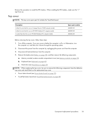
... top cover and install them on the replacement top cover: ● Power button board (see Power button board on page 57) ● TouchPad button board (see Memory module on page 43) c. When installing the RTC battery, make sure the "+" sign faces up. Hard drive (see Hard drive on , and then shut it down through the operating system. 2. Top cover NOTE: The top cover spare part kit includes the TouchPad board. Disconnect all external devices from the computer. 3. Disconnect the power from...
... top cover and install them on the replacement top cover: ● Power button board (see Power button board on page 57) ● TouchPad button board (see Memory module on page 43) c. When installing the RTC battery, make sure the "+" sign faces up. Hard drive (see Hard drive on , and then shut it down through the operating system. 2. Top cover NOTE: The top cover spare part kit includes the TouchPad board. Disconnect all external devices from the computer. 3. Disconnect the power from...
Maintenance and Service Guide
Page 93
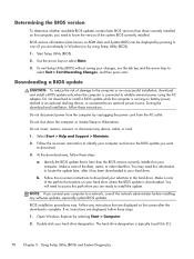
... install a BIOS update only when the computer is running on battery power, docked in Windows) or by selecting Start > Computer. 2. Follow any instructions that is complete. The hard drive designation is downloaded. Make a note of the path to an optional power source. To exit Setup Utility (BIOS) without saving your computer to a network, consult the network administrator before installing any device, cable, or cord. 1. Do not shut down the computer or initiate Sleep...
... install a BIOS update only when the computer is running on battery power, docked in Windows) or by selecting Start > Computer. 2. Follow any instructions that is complete. The hard drive designation is downloaded. Make a note of the path to an optional power source. To exit Setup Utility (BIOS) without saving your computer to a network, consult the network administrator before installing any device, cable, or cord. 1. Do not shut down the computer or initiate Sleep...

Maintenance and Service Guide
Page 99
... DVD+R DL discs. To create a set of recovery discs or a recovery flash drive: 1. NOTE: Read-write discs, such as a USB hub. Handle these discs or the flash drive after setting up the computer for any reason you cannot restore using the recovery partition tools. Select Start > All Programs > HP Help and Support > HP Recovery Manager > HP Recovery Media Creation. 2. Create these discs or the flash drive carefully and keep them in a safe place. Creating recovering media HP recommends that you create either a set of recovery discs or a recovery flash drive...
... DVD+R DL discs. To create a set of recovery discs or a recovery flash drive: 1. NOTE: Read-write discs, such as a USB hub. Handle these discs or the flash drive after setting up the computer for any reason you cannot restore using the recovery partition tools. Select Start > All Programs > HP Help and Support > HP Recovery Manager > HP Recovery Media Creation. 2. Create these discs or the flash drive carefully and keep them in a safe place. Creating recovering media HP recommends that you create either a set of recovery discs or a recovery flash drive...

Maintenance and Service Guide
Page 108
... jack 13 B base enclosure, spare part number 21, 29 battery removal 38 spare part numbers 21, 27, 38 battery bay 16 battery release latch 16 bottom components 16 button component 9 buttons optical drive eject 15 power 9 TouchPad 12 TouchPad on/off 12 C cables, service considerations 31 caps lock light 11 chipset, product description 2 components bottom 16 button 9 display 7 front 12 keys 10 left-side 13 lights 11 right-side 15 TouchPad 12 computer feet locations...
... jack 13 B base enclosure, spare part number 21, 29 battery removal 38 spare part numbers 21, 27, 38 battery bay 16 battery release latch 16 bottom components 16 button component 9 buttons optical drive eject 15 power 9 TouchPad 12 TouchPad on/off 12 C cables, service considerations 31 caps lock light 11 chipset, product description 2 components bottom 16 button 9 display 7 front 12 keys 10 left-side 13 lights 11 right-side 15 TouchPad 12 computer feet locations...
Maintenance and Service Guide
Page 109
... 10 Windows applications 10 Windows logo 10 L left-side components 13 light components 11 lights AC adapter 15 caps lock 11 hard drive 14 optical drive 15 power 11, 14 TouchPad 12 webcam 8 wireless 11 M mass storage device illustrated 25 precautions 32 memory module product description 3 removal 39 spare part numbers 22, 27, 28, 39 memory module/wireless module compartment cover location 16 removal 39 spare part number 29, 39 microphone location 7 product description 3 microphone jack 13 model description 37 model name 1 monitor port 13 N network jack 13 O operating...
... 10 Windows applications 10 Windows logo 10 L left-side components 13 light components 11 lights AC adapter 15 caps lock 11 hard drive 14 optical drive 15 power 11, 14 TouchPad 12 webcam 8 wireless 11 M mass storage device illustrated 25 precautions 32 memory module product description 3 removal 39 spare part numbers 22, 27, 28, 39 memory module/wireless module compartment cover location 16 removal 39 spare part number 29, 39 microphone location 7 product description 3 microphone jack 13 model description 37 model name 1 monitor port 13 N network jack 13 O operating...
Maintenance and Service Guide
Page 110
... part number 26, 30 security cable slot 15 security, product description 5 serial number 36 service considerations cables 31 connectors 31 plastic parts 31 service tag 18, 36 serviceability, product description 6 speakers location 12 removal 63 spare part number 21, 30, 63 specifications computer 87 display 88 hard drive 89 V vents 13, 16 video, product description 3 W warranty period 37 webcam 8 webcam light 8 webcam/microphone module removal 81 spare part number 23, 30, 81 Windows applications key 10 Windows logo key 10 wireless antenna locations 7 removal 81 spare part number...
... part number 26, 30 security cable slot 15 security, product description 5 serial number 36 service considerations cables 31 connectors 31 plastic parts 31 service tag 18, 36 serviceability, product description 6 speakers location 12 removal 63 spare part number 21, 30, 63 specifications computer 87 display 88 hard drive 89 V vents 13, 16 video, product description 3 W warranty period 37 webcam 8 webcam light 8 webcam/microphone module removal 81 spare part number 23, 30, 81 Windows applications key 10 Windows logo key 10 wireless antenna locations 7 removal 81 spare part number...

Maintenance and Service Guide 1
Page 52
... 320-GB, 5400-rpm, 9.5-mm Hard Drive Hardware Kit (includes hard drive bracket, hard drive connector cable, and screws) Spare part number 669300-001 669299-001 622643-001 686261-001 Before removing the hard drive, follow these steps: 1. Lift the rear edge of the hard drive compartment cover (2) up and forward until it down through the operating system. 2. Remove the memory module/wireless module compartment cover (see Battery on , and then shut it rests...
... 320-GB, 5400-rpm, 9.5-mm Hard Drive Hardware Kit (includes hard drive bracket, hard drive connector cable, and screws) Spare part number 669300-001 669299-001 622643-001 686261-001 Before removing the hard drive, follow these steps: 1. Lift the rear edge of the hard drive compartment cover (2) up and forward until it down through the operating system. 2. Remove the memory module/wireless module compartment cover (see Battery on , and then shut it rests...

Maintenance and Service Guide 1
Page 55
Remove the battery (see Battery on page 35). 6. Remove the memory module/wireless module compartment cover (see Hard drive on , and then shut it down through the operating system. 2. Remove the hard drive compartment cover (see Memory module on page 34). 5. Use a flat-bladed, non-metallic tool (1) to release the RTC battery from the computer. 3. Disconnect the power from the computer by unplugging the power cord from the socket on the system board. 2. Remove the...
Remove the battery (see Battery on page 35). 6. Remove the memory module/wireless module compartment cover (see Hard drive on , and then shut it down through the operating system. 2. Remove the hard drive compartment cover (see Memory module on page 34). 5. Use a flat-bladed, non-metallic tool (1) to release the RTC battery from the computer. 3. Disconnect the power from the computer by unplugging the power cord from the socket on the system board. 2. Remove the...
Maintenance and Service Guide 1
Page 86
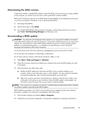
... displayed on battery power, docked in Windows) or by pressing fn +esc (if you want to the hard drive. During the download and installation, follow these steps: a. Follow any device, cable, or cord. 1. Follow the on -screen instructions to download your computer to install the update. Make a note of the date, name, or other identifier. BIOS version information (also known as ROM date and System BIOS) can be displayed by using...
... displayed on battery power, docked in Windows) or by pressing fn +esc (if you want to the hard drive. During the download and installation, follow these steps: a. Follow any device, cable, or cord. 1. Follow the on -screen instructions to download your computer to install the update. Make a note of the date, name, or other identifier. BIOS version information (also known as ROM date and System BIOS) can be displayed by using...
Maintenance and Service Guide 1
Page 90
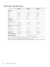
... 100.4 mm 100.4 mm 100.4 mm Width 69.9 mm 69.9 mm 69.9 mm Weight 110 g 110 g 110 g Interface type SATA SATA SATA Transfer rate Synchronous (maximum) 1.1 GB/sec 1.1 GB/sec 1.1 GB/sec Security ATA security ATA security ATA security Seek times (typical read, including setting)...Disk rotational speed 5400 rpm 5400 rpm 5400 rpm Operating temperature 0°C to 60°C (32°F to 140°F) *1 GB = 1 billion bytes when referring to hard drive storage capacity. Actual accessible capacity is less. Contact technical support for details. 82 Chapter 6 Specifications...
... 100.4 mm 100.4 mm 100.4 mm Width 69.9 mm 69.9 mm 69.9 mm Weight 110 g 110 g 110 g Interface type SATA SATA SATA Transfer rate Synchronous (maximum) 1.1 GB/sec 1.1 GB/sec 1.1 GB/sec Security ATA security ATA security ATA security Seek times (typical read, including setting)...Disk rotational speed 5400 rpm 5400 rpm 5400 rpm Operating temperature 0°C to 60°C (32°F to 140°F) *1 GB = 1 billion bytes when referring to hard drive storage capacity. Actual accessible capacity is less. Contact technical support for details. 82 Chapter 6 Specifications...
Maintenance and Service Guide 1
Page 91
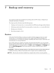
... a recovery flash drive) ● Backing up your information ● Recovering a program or driver Restore In the event of recovery discs or a recovery flash drive. Restore 83 To check for the presence of recovery discs or a recovery flash drive that was installed at the factory. NOTE: Recovery discs have been included if your system to its factory image you use HP Recovery Manager immediately after software setup to create either a set of a recovery partition, click Start, right-click Computer, click Manage, and then click Disk Management. 7 Backup...
... a recovery flash drive) ● Backing up your information ● Recovering a program or driver Restore In the event of recovery discs or a recovery flash drive. Restore 83 To check for the presence of recovery discs or a recovery flash drive that was installed at the factory. NOTE: Recovery discs have been included if your system to its factory image you use HP Recovery Manager immediately after software setup to create either a set of a recovery partition, click Start, right-click Computer, click Manage, and then click Disk Management. 7 Backup...
Maintenance and Service Guide 1
Page 101
... audio-out jack 11 B base enclosure, spare part number 19, 25 battery removal 34 spare part numbers 19, 24, 34 battery bay 14 battery release latch 14 bottom components 14 button component 7 buttons optical drive eject 13 power 7 TouchPad 10 TouchPad on/off 10 C cables, service considerations 27 caps lock light 9 chipset, product description 1 components bottom 14 button 7 display 5 front 10 keys 8 left-side 11 lights 9 right-side 13 TouchPad 10 computer feet locations 33 spare part number...
... audio-out jack 11 B base enclosure, spare part number 19, 25 battery removal 34 spare part numbers 19, 24, 34 battery bay 14 battery release latch 14 bottom components 14 button component 7 buttons optical drive eject 13 power 7 TouchPad 10 TouchPad on/off 10 C cables, service considerations 27 caps lock light 9 chipset, product description 1 components bottom 14 button 7 display 5 front 10 keys 8 left-side 11 lights 9 right-side 13 TouchPad 10 computer feet locations 33 spare part number...
Maintenance and Service Guide 1
Page 102
... 3 ports external monitor port 11 HDMI 11 monitor port 11 product description 3 USB 11, 13 power button 7 power button board removal 51 spare part number 18, 25, 51 power connector 13 power connector cable removal 75 spare part number 19, 25, 75 power cord set requirements 90 spare part numbers 23, 24 power light 9, 12 power requirements, product description 3 processor product description 1 product description audio 2 chipset 1 display panel 1 Ethernet 2 external media cards 3 graphics 1 hard drive 2 keyboard 3 memory module 2 microphone 2 operating system 4 optical drive 2 pointing device...
... 3 ports external monitor port 11 HDMI 11 monitor port 11 product description 3 USB 11, 13 power button 7 power button board removal 51 spare part number 18, 25, 51 power connector 13 power connector cable removal 75 spare part number 19, 25, 75 power cord set requirements 90 spare part numbers 23, 24 power light 9, 12 power requirements, product description 3 processor product description 1 product description audio 2 chipset 1 display panel 1 Ethernet 2 external media cards 3 graphics 1 hard drive 2 keyboard 3 memory module 2 microphone 2 operating system 4 optical drive 2 pointing device...


