Software Guide
Page 35
... information that previously was in Catalyst 6500 series switches. Product Overview CH A P T E R 1 The Catalyst 6000 family switches support the following configurations: • Supervisor Engine 2, Policy Feature Card 2 (PFC2), and Multilayer Switch Feature Card 2 (MSFC2) • Supervisor Engine 2 and PFC2 • Supervisor Engine 1, PFC, and MSFC or MSFC2 • Supervisor Engine 1 and PFC • Supervisor Engine 1 Note The Switch Fabric Module is...
... information that previously was in Catalyst 6500 series switches. Product Overview CH A P T E R 1 The Catalyst 6000 family switches support the following configurations: • Supervisor Engine 2, Policy Feature Card 2 (PFC2), and Multilayer Switch Feature Card 2 (MSFC2) • Supervisor Engine 2 and PFC2 • Supervisor Engine 1, PFC, and MSFC or MSFC2 • Supervisor Engine 1 and PFC • Supervisor Engine 1 Note The Switch Fabric Module is...

Software Guide
Page 303
...page 16-7 • Multicast Packets, page 16-8 Bridged Packets Figure 16-1 shows how an ACL is applied on routed/Layer 3-switched packets. Input Cisco IOS ACL 3. For bridged packets, only Layer 2 ACLs are applied on bridged packets. Figure 16-1 Applying ACLs on Bridged Packets VACL Bridged Host ...A (VLAN 10) Catalyst 6500 Series Switch with PFC Host B (VLAN 10) 26961 Routed Packets Figure 16-2 shows how ACLs are applied to the VLAN for bridged packets,...
...page 16-7 • Multicast Packets, page 16-8 Bridged Packets Figure 16-1 shows how an ACL is applied on routed/Layer 3-switched packets. Input Cisco IOS ACL 3. For bridged packets, only Layer 2 ACLs are applied on bridged packets. Figure 16-1 Applying ACLs on Bridged Packets VACL Bridged Host ...A (VLAN 10) Catalyst 6500 Series Switch with PFC Host B (VLAN 10) 26961 Routed Packets Figure 16-2 shows how ACLs are applied to the VLAN for bridged packets,...

Software Guide
Page 304
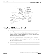
... applied on Routed Packets Routed Input IOS ACL Bridged VACL MSFC Output IOS ACL VACL Bridged Host A (VLAN 10) Catalyst 6500 series switches with MSFC Host B (VLAN 20) 26964 Multicast Packets Figure 16-3 shows how ACLs are applied in the following order: 1. Output... Cisco IOS ACL b. VACL for output VLAN 3. Packets originating from router: a. Applying Cisco IOS ACLs and VACLs on VLANs Chapter 16 Configuring Access Control Figure 16-2 Applying ACLs on packets that need...
... applied on Routed Packets Routed Input IOS ACL Bridged VACL MSFC Output IOS ACL VACL Bridged Host A (VLAN 10) Catalyst 6500 series switches with MSFC Host B (VLAN 20) 26964 Multicast Packets Figure 16-3 shows how ACLs are applied in the following order: 1. Output... Cisco IOS ACL b. VACL for output VLAN 3. Packets originating from router: a. Applying Cisco IOS ACLs and VACLs on VLANs Chapter 16 Configuring Access Control Figure 16-2 Applying ACLs on packets that need...
Software Guide
Page 305
... Software Configuration Guide-Releases 6.3 and 6.4 16-9 For example, to configure ACLs for IP, refer to this process as configuring ACLs on other Cisco routers. The router then applies the feature and routes the packet normally. Note In systems with redundant MSFCs, the ACL configurations for packets originating...Network Figure 16-3 Applying ACLs on Multicast Packets Routed Input IOS ACL Bridged VACL Catalyst 6500 Series Switch with MSFC MSFC Host A (VLAN 10) Host C (VLAN 10) Bridged IOS ACL for output VLAN for Cisco IOS ACLs and VACLs must be the same on page 16-28. In addition,...
... Software Configuration Guide-Releases 6.3 and 6.4 16-9 For example, to configure ACLs for IP, refer to this process as configuring ACLs on other Cisco routers. The router then applies the feature and routes the packet normally. Note In systems with redundant MSFCs, the ACL configurations for packets originating...Network Figure 16-3 Applying ACLs on Multicast Packets Routed Input IOS ACL Bridged VACL Catalyst 6500 Series Switch with MSFC MSFC Host A (VLAN 10) Host C (VLAN 10) Bridged IOS ACL for output VLAN for Cisco IOS ACLs and VACLs must be the same on page 16-28. In addition,...

Software Guide
Page 319
... Server Port Some application traffic uses broadcast packets that reach every host in a VLAN. Chapter 16 Configuring Access Control Figure 16-4 Wiring Closet Configuration Catalyst 6500 series switches with MSFC Using VACLs in your Network Switch A with PFC only VACL: deny http from X to Y http is the intended server application port...
... Server Port Some application traffic uses broadcast packets that reach every host in a VLAN. Chapter 16 Configuring Access Control Figure 16-4 Wiring Closet Configuration Catalyst 6500 series switches with MSFC Using VACLs in your Network Switch A with PFC only VACL: deny http from X to Y http is the intended server application port...

Software Guide
Page 320
Commit the VACL. Map the VACL to a Specific Server Port VACL Target server Host A 4/1 Catalyst 6500 series switches with PFC Host B VLAN 10 Application broadcast packet Host C 26960 Restricting the DHCP Response for a specific server, perform this task in privileged mode (...
Commit the VACL. Map the VACL to a Specific Server Port VACL Target server Host A 4/1 Catalyst 6500 series switches with PFC Host B VLAN 10 Application broadcast packet Host C 26960 Restricting the DHCP Response for a specific server, perform this task in privileged mode (...

Software Guide
Page 321
...-13315-02 Catalyst 6000 Family Software Configuration Guide-Releases 6.3 and 6.4 16-25 Figure 16-6 Redirect DHCP Response for a Specific Server VACL Target server 1.2.3.4 Host A Catalyst 6500 series switches with PFC VLAN 10 DHCP response packets Host B Host C 26962 Denying Access to a Server on Another VLAN You can restrict access to a server...
...-13315-02 Catalyst 6000 Family Software Configuration Guide-Releases 6.3 and 6.4 16-25 Figure 16-6 Redirect DHCP Response for a Specific Server VACL Target server 1.2.3.4 Host A Catalyst 6500 series switches with PFC VLAN 10 DHCP response packets Host B Host C 26962 Denying Access to a Server on Another VLAN You can restrict access to a server...

Software Guide
Page 322
.... ARP traffic is permitted on Another VLAN VACL 10.1.1.100 Server (VLAN 10) 10.1.1.4 Host (VLAN 10) 10.1.1.8 Host (VLAN 10) Catalyst 6500 series switches with PFC Subnet 10.1.2.0/24 Host (VLAN 20) 26963 Restricting ARP Traffic Note This feature is disallowed on a primary VLAN only and the...8226; Cisco IOS ACLs that has had ARP traffic disallowed, enter the set security acl ip acl_name deny arp command. When you map a VACL to a secondary VLAN, it filters the traffic from the router to the host and if you enter this command, ARP traffic is only available with Supervisor Engine 2 ...
.... ARP traffic is permitted on Another VLAN VACL 10.1.1.100 Server (VLAN 10) 10.1.1.4 Host (VLAN 10) 10.1.1.8 Host (VLAN 10) Catalyst 6500 series switches with PFC Subnet 10.1.2.0/24 Host (VLAN 20) 26963 Restricting ARP Traffic Note This feature is disallowed on a primary VLAN only and the...8226; Cisco IOS ACLs that has had ARP traffic disallowed, enter the set security acl ip acl_name deny arp command. When you map a VACL to a secondary VLAN, it filters the traffic from the router to the host and if you enter this command, ARP traffic is only available with Supervisor Engine 2 ...

Software Guide
Page 344
... the example configuration shown in the Edit Buffer, page 16-53 • Configuring Hosts for PBF, page 16-53 Figure 16-8 Policy-Based Forwarding Catalyst 6500 series switches PFC2 MAC address: 00-11-11-11-11-11 VLAN 10 Host A IP 10.0.0.1 MAC 00:00:00:00:00:0A Interface: Ethernet1...
... the example configuration shown in the Edit Buffer, page 16-53 • Configuring Hosts for PBF, page 16-53 Figure 16-8 Policy-Based Forwarding Catalyst 6500 series switches PFC2 MAC address: 00-11-11-11-11-11 VLAN 10 Host A IP 10.0.0.1 MAC 00:00:00:00:00:0A Interface: Ethernet1...

Software Guide
Page 352
Configuring Policy-Based Forwarding Chapter 16 Configuring Access Control Figure 16-9 Policy-Based Forwarding Configuration Example Catalyst 6500 series switches PFC2 MAC address: 00-11-22-33-44-55 6/17 6/9 VLAN 1 VLAN 1 Hosts IP: 44.0.0.1 - 44.0.0.17 MAC:00-20-20-20-20-...
Configuring Policy-Based Forwarding Chapter 16 Configuring Access Control Figure 16-9 Policy-Based Forwarding Configuration Example Catalyst 6500 series switches PFC2 MAC address: 00-11-22-33-44-55 6/17 6/9 VLAN 1 VLAN 1 Hosts IP: 44.0.0.1 - 44.0.0.17 MAC:00-20-20-20-20-...

Software Guide
Page 375
Chapter 18 Configuring Dynamic Port VLAN Membership with VMPS Dynamic Port VLAN Membership with VMPS Configuration Examples Figure 18-1 Dynamic Port VLAN Membership Configuration Catalyst 6500 series switches Primary VMPS Server 1 Switch 1 172.20.26.150 3/1 Client End station 1 Switch 2 172.20.26.151 Catalyst 6000 ...20.22.7 Switch 7 172.20.26.156 Switch 8 172.20.26.157 Client Switch 9 End station 2 172.20.26.158 Catalyst 6500 series switches Secondary VMPS Server 3 Switch 10 172.20.26.159 55908 78-13315-02 Catalyst 6000 Family Software Configuration Guide-Releases 6.3 and ...
Chapter 18 Configuring Dynamic Port VLAN Membership with VMPS Dynamic Port VLAN Membership with VMPS Configuration Examples Figure 18-1 Dynamic Port VLAN Membership Configuration Catalyst 6500 series switches Primary VMPS Server 1 Switch 1 172.20.26.150 3/1 Client End station 1 Switch 2 172.20.26.151 Catalyst 6000 ...20.22.7 Switch 7 172.20.26.156 Switch 8 172.20.26.157 Client Switch 9 End station 2 172.20.26.158 Catalyst 6500 series switches Secondary VMPS Server 3 Switch 10 172.20.26.159 55908 78-13315-02 Catalyst 6000 Family Software Configuration Guide-Releases 6.3 and ...

Software Guide
Page 416
... the Telnet client can use another TGT in -band management port. Figure 21-1 Kerberized Telnet Connection Host (Telnet client) Kerberos server 1 (contains KDC) 2 3 4 5 6 6000 Catalyst 6500 series switches 30794 21-6 Catalyst 6000 Family Software Configuration Guide-Releases 6.3 and 6.4 78-13315-02 The KDC then encrypts the credential with the password that...
... the Telnet client can use another TGT in -band management port. Figure 21-1 Kerberized Telnet Connection Host (Telnet client) Kerberos server 1 (contains KDC) 2 3 4 5 6 6000 Catalyst 6500 series switches 30794 21-6 Catalyst 6000 Family Software Configuration Guide-Releases 6.3 and 6.4 78-13315-02 The KDC then encrypts the credential with the password that...

Software Guide
Page 707
...best-effort delivery basis, which means that all traffic has equal priority and an equal chance of being dropped. When congestion occurs, all Catalyst 6500 series documents, the term "QoS" refers to the Catalyst 6000 Family Command Reference publication. Configuring QoS 41 C H A P T E ...avoidance techniques. Note For complete syntax and usage information for ingress traffic. Typically, networks operate on the Catalyst 6500 series. • Supervisor Engine 1 and Supervisor Engine 2 provide policing only for the commands used in this publication and all traffic has an equal chance of ...
...best-effort delivery basis, which means that all traffic has equal priority and an equal chance of being dropped. When congestion occurs, all Catalyst 6500 series documents, the term "QoS" refers to the Catalyst 6000 Family Command Reference publication. Configuring QoS 41 C H A P T E ...avoidance techniques. Note For complete syntax and usage information for ingress traffic. Typically, networks operate on the Catalyst 6500 series. • Supervisor Engine 1 and Supervisor Engine 2 provide policing only for the commands used in this publication and all traffic has an equal chance of ...

Software Guide
Page 783
...-Releases 6.3 and 6.4 42-3 Xtag = The identifier field in Figure 42-1). Chapter 42 Configuring ASLB Understanding How ASLB Works Figure 42-1 ASLB Functional Description Clients Catalyst 6500 series switches PK PR PL PA PB PM Server pool S1 S2 S3 28062 VLAN 10 VLAN 20 LocalDirector Layer 3 Operations for ASLB You can...
...-Releases 6.3 and 6.4 42-3 Xtag = The identifier field in Figure 42-1). Chapter 42 Configuring ASLB Understanding How ASLB Works Figure 42-1 ASLB Functional Description Clients Catalyst 6500 series switches PK PR PL PA PB PM Server pool S1 S2 S3 28062 VLAN 10 VLAN 20 LocalDirector Layer 3 Operations for ASLB You can...

Software Guide
Page 785
... = client's IP address. 3. VIP = virtual-IP address. 2. Chapter 42 Configuring ASLB Understanding How ASLB Works Figure 42-2 Client to Server ASLB Packet Flow Clients Catalyst 6500 series switches Path 3 PK PR PL PA PB PM Path 1 Path 2 Server pool S1 S2 S3 VLAN 10 VLAN 20 LocalDirector 28063 Table 42-2 Client...
... = client's IP address. 3. VIP = virtual-IP address. 2. Chapter 42 Configuring ASLB Understanding How ASLB Works Figure 42-2 Client to Server ASLB Packet Flow Clients Catalyst 6500 series switches Path 3 PK PR PL PA PB PM Path 1 Path 2 Server pool S1 S2 S3 VLAN 10 VLAN 20 LocalDirector 28063 Table 42-2 Client...

Software Guide
Page 786
... of the packet for this packet's VLAN. 2. VIP = virtual-IP address. Figure 42-3 Server to Client ASLB Packet Flow Clients VLAN 10 VLAN 20 Catalyst 6500 series switches Path 3 PK Server pool S1 S2 S3 PR PL PA PB PM Path 2 Path 1 LocalDirector 28064 Table 42-4 Server to the clients.
... of the packet for this packet's VLAN. 2. VIP = virtual-IP address. Figure 42-3 Server to Client ASLB Packet Flow Clients VLAN 10 VLAN 20 Catalyst 6500 series switches Path 3 PK Server pool S1 S2 S3 PR PL PA PB PM Path 2 Path 1 LocalDirector 28064 Table 42-4 Server to the clients.

Software Guide
Page 799
... configuration is the default for the virtual-IP address 192.255.201.55. Figure 42-4 ASLB Configuration Example Server pool Clients VLAN 7 VLAN 5 S1 Catalyst 6500 series switches 5/n 5/6 5/n S2 5/7 5/5 5/n S3 LocalDirector S 28229 78-13315-02 The router configuration is as follows: Console (enable) show lda Status:Committed Virtual IP addresses: Catalyst...
... configuration is the default for the virtual-IP address 192.255.201.55. Figure 42-4 ASLB Configuration Example Server pool Clients VLAN 7 VLAN 5 S1 Catalyst 6500 series switches 5/n 5/6 5/n S2 5/7 5/5 5/n S3 LocalDirector S 28229 78-13315-02 The router configuration is as follows: Console (enable) show lda Status:Committed Virtual IP addresses: Catalyst...

Software Guide
Page 802
... ASLB Figure 42-5 ASLB Redundant Configuration Example LocalDirector 1 Clients VLAN 9 VLAN 5 Router 1 3/7 f1 f2 3/41 VLAN 9 3/23 3/8 Catalyst 6500 series switches 1 VLAN 5 VLAN 5 & 9 (ISL trunk) Router 2 3/23 f1 f2 3/42 VLAN 9 3/27 Catalyst 6500 series switches 2 3/28 VLAN 5 VLAN 9 VLAN 5 LocalDirector LocalDirector 2 failover cable IP Addresses The IP addresses are as follows...
... ASLB Figure 42-5 ASLB Redundant Configuration Example LocalDirector 1 Clients VLAN 9 VLAN 5 Router 1 3/7 f1 f2 3/41 VLAN 9 3/23 3/8 Catalyst 6500 series switches 1 VLAN 5 VLAN 5 & 9 (ISL trunk) Router 2 3/23 f1 f2 3/42 VLAN 9 3/27 Catalyst 6500 series switches 2 3/28 VLAN 5 VLAN 9 VLAN 5 LocalDirector LocalDirector 2 failover cable IP Addresses The IP addresses are as follows...

Software Guide
Page 807
...The Switch Fabric Module also provides fabric-enabled modules with Supervisor Engine 2 in the Catalyst 6500 series switch. If you specify bus-mode, the switching is supported only with a direct connection to the Catalyst 6500 32-Gbps forwarding bus. A two-line LCD display ... E R Configuring the Switch Fabric Modules This chapter describes how to configure the Switch Fabric Module (WS-C6500-SFM) and Switch Fabric Module 2 (WS-X6500-SFM 2) for the commands used in the Catalyst 6500 6-and 9-slot chassis only. This chapter consists of frames between these sections: • Understanding How...
...The Switch Fabric Module also provides fabric-enabled modules with Supervisor Engine 2 in the Catalyst 6500 series switch. If you specify bus-mode, the switching is supported only with a direct connection to the Catalyst 6500 32-Gbps forwarding bus. A two-line LCD display ... E R Configuring the Switch Fabric Modules This chapter describes how to configure the Switch Fabric Module (WS-C6500-SFM) and Switch Fabric Module 2 (WS-X6500-SFM 2) for the commands used in the Catalyst 6500 6-and 9-slot chassis only. This chapter consists of frames between these sections: • Understanding How...

Software Guide
Page 808
... Modules When you install a Switch Fabric Module in a Catalyst 6500 series switch, the traffic is forwarded to or from modules in one of these modes: • Flow-through mode-Data passes between the local bus and the supervisor engine bus. Table 43-1 Switching Modes with both the destination and ...9-slot chassis, the primary module is in slot 6. This mode is in slot 5 and the backup is used for monitoring purposes. From the supervisor engine, you reset the module in slot 7, the module in compact mode. If you can reset the module using the reset module command, disable and ...
... Modules When you install a Switch Fabric Module in a Catalyst 6500 series switch, the traffic is forwarded to or from modules in one of these modes: • Flow-through mode-Data passes between the local bus and the supervisor engine bus. Table 43-1 Switching Modes with both the destination and ...9-slot chassis, the primary module is in slot 6. This mode is in slot 5 and the backup is used for monitoring purposes. From the supervisor engine, you reset the module in slot 7, the module in compact mode. If you can reset the module using the reset module command, disable and ...