
Hardware Maintenance Manual
Page 3
... the Software error, (6) has been exported from the date of the hardware less depreciation calculated on a straight-line basis. All rights reserved. Printed in this manual is subject to such copy all warranted problems within the warranty period to the party that Cisco or its networks without the prior consent of Cisco. Cisco warrants that aspects of the licensed materials, including the specific...
... the Software error, (6) has been exported from the date of the hardware less depreciation calculated on a straight-line basis. All rights reserved. Printed in this manual is subject to such copy all warranted problems within the warranty period to the party that Cisco or its networks without the prior consent of Cisco. Cisco warrants that aspects of the licensed materials, including the specific...

Hardware Maintenance Manual
Page 7
... Four-Port Serial Module Cable Assembly A-15 EIA-530 Dual Serial Module Cable Assembly A-16 EIA-530 Four-Port Serial Module Cable Assembly A-18 Ethernet Cable Pinouts A-19 Ethernet (AUI) Cable Pinouts A-19 RJ-45 10BaseT Connector Pinouts A-20 Token Ring Port Pinout A-21 BRI Pinout A-22 Channelized T1 Pinouts A-22 Channelized E1 Pinouts A-23 Appendix B Cisco 4000 Series Virtual Configuration Register B-1 Virtual Configuration Register Settings B-1 Changing Configuration Register Settings B-2 Configuring the Boot Field B-3 Enabling Booting from Flash Memory B-6 Appendix C Cisco...
... Four-Port Serial Module Cable Assembly A-15 EIA-530 Dual Serial Module Cable Assembly A-16 EIA-530 Four-Port Serial Module Cable Assembly A-18 Ethernet Cable Pinouts A-19 Ethernet (AUI) Cable Pinouts A-19 RJ-45 10BaseT Connector Pinouts A-20 Token Ring Port Pinout A-21 BRI Pinout A-22 Channelized T1 Pinouts A-22 Channelized E1 Pinouts A-23 Appendix B Cisco 4000 Series Virtual Configuration Register B-1 Virtual Configuration Register Settings B-1 Changing Configuration Register Settings B-2 Configuring the Boot Field B-3 Enabling Booting from Flash Memory B-6 Appendix C Cisco...

Hardware Maintenance Manual
Page 9
...-NRZI Setting 2-21 Router Serial Cable Connections 2-21 Dual-Attachment Single-Mode FDDI Module-End View 2-25 Single-Mode FDDI Network Interface Connectors, FC Type 2-26 Multimode FDDI Network Interface Connector, MIC Type 2-26 Dual-Attachment Multimode FDDI Module-End View 2-27 Dual-Attachment FDDI Optical Bypass Switch and PHY Connections 2-27 Single-Attachment Multimode FDDI Module-End View 2-28 4-Port BRI Network Processor Module 2-29 8-Port BRI Network Processor Module 2-29 Channelized T1 Network Interface Processor 2-31 List of...
...-NRZI Setting 2-21 Router Serial Cable Connections 2-21 Dual-Attachment Single-Mode FDDI Module-End View 2-25 Single-Mode FDDI Network Interface Connectors, FC Type 2-26 Multimode FDDI Network Interface Connector, MIC Type 2-26 Dual-Attachment Multimode FDDI Module-End View 2-27 Dual-Attachment FDDI Optical Bypass Switch and PHY Connections 2-27 Single-Attachment Multimode FDDI Module-End View 2-28 4-Port BRI Network Processor Module 2-29 8-Port BRI Network Processor Module 2-29 Channelized T1 Network Interface Processor 2-31 List of...

Hardware Maintenance Manual
Page 10
... AC-Input Power Supply-Rear View 3-20 DC-Input Power Supply Connections 3-21 Cisco 4000 Series-Front Panel Indicators 4-3 Dual-Port Ethernet Network Processor Module LEDs 4-4 Single-Port Ethernet Network Processor Module LEDs 4-4 Token Ring Module Network Connector 4-5 Four-Port Serial Network Processor Module Ports 4-6 G.703/G.704 Serial Network Processor Module Ports (DB-15) 4-6 Serial Port Labeled V2 4-7 Dual Serial Network Processor Module-Top View 4-8 Dual Serial Port LED Card-Side View 4-8 Dual-Attachment Single-Mode FDDI Module-End View 4-9 x Cisco 4000 Series Hardware Installation and...
... AC-Input Power Supply-Rear View 3-20 DC-Input Power Supply Connections 3-21 Cisco 4000 Series-Front Panel Indicators 4-3 Dual-Port Ethernet Network Processor Module LEDs 4-4 Single-Port Ethernet Network Processor Module LEDs 4-4 Token Ring Module Network Connector 4-5 Four-Port Serial Network Processor Module Ports 4-6 G.703/G.704 Serial Network Processor Module Ports (DB-15) 4-6 Serial Port Labeled V2 4-7 Dual Serial Network Processor Module-Top View 4-8 Dual Serial Port LED Card-Side View 4-8 Dual-Attachment Single-Mode FDDI Module-End View 4-9 x Cisco 4000 Series Hardware Installation and...

Hardware Maintenance Manual
Page 11
... 5-3 Component Tray Removal for Chassis Without a Safety Latch 5-4 Typical Cisco 4000 Series Component Tray-Cisco 4000-M Shown 5-5 Network Processor Module Locations 5-6 Cisco 4000-M SIMM Locations 5-7 Cisco 4500-M and Cisco 4700 SIMM Locations 5-8 Cisco 4000 Series Main Memory SIMM 5-8 Removing Main Memory SIMMs 5-10 Installing Main Memory SIMMs 5-12 Inserting Shared-Memory SIMMs 5-15 Removing the Boot Helper Flash Memory SIMM 5-16 Inserting Flash-Memory SIMMs 5-18 Boot ROMs Locations 5-19 Dual Serial EIA/TIA-232 Cable Assembly...
... 5-3 Component Tray Removal for Chassis Without a Safety Latch 5-4 Typical Cisco 4000 Series Component Tray-Cisco 4000-M Shown 5-5 Network Processor Module Locations 5-6 Cisco 4000-M SIMM Locations 5-7 Cisco 4500-M and Cisco 4700 SIMM Locations 5-8 Cisco 4000 Series Main Memory SIMM 5-8 Removing Main Memory SIMMs 5-10 Installing Main Memory SIMMs 5-12 Inserting Shared-Memory SIMMs 5-15 Removing the Boot Helper Flash Memory SIMM 5-16 Inserting Flash-Memory SIMMs 5-18 Boot ROMs Locations 5-19 Dual Serial EIA/TIA-232 Cable Assembly...

Hardware Maintenance Manual
Page 15
...-input power supply. Document Organization The major sections of the Cisco 4000 series features and physical specifications. • Chapter 2, "Preparing for Installation," includes safety recommendations, tools and equipment, site requirements, an installation checklist, console and auxiliary port cable connection considerations, network connection considerations, and instructions for inspecting the new system. • Chapter 3, "Installing the Router," includes instructions for the router installer, who should be more up to the appropriate software publication...
...-input power supply. Document Organization The major sections of the Cisco 4000 series features and physical specifications. • Chapter 2, "Preparing for Installation," includes safety recommendations, tools and equipment, site requirements, an installation checklist, console and auxiliary port cable connection considerations, network connection considerations, and instructions for inspecting the new system. • Chapter 3, "Installing the Router," includes instructions for the router installer, who should be more up to the appropriate software publication...

Hardware Maintenance Manual
Page 16
... time. Samples use in square brackets ([ ]). Note Means reader take note. Document Conventions • Chapter 4, "Troubleshooting the Initial Hardware Configuration," includes a troubleshooting overview, problem-solving instructions, environmental reporting features, and understanding front-panel and network-processor module LED indicators. • Chapter 5, "Maintaining and Upgrading the Router," includes instructions for opening the chassis, replacing or adding network processor modules, and replacing single in-line memory modules (SIMMs). • Appendix A, "Cabling Specifications...
... time. Samples use in square brackets ([ ]). Note Means reader take note. Document Conventions • Chapter 4, "Troubleshooting the Initial Hardware Configuration," includes a troubleshooting overview, problem-solving instructions, environmental reporting features, and understanding front-panel and network-processor module LED indicators. • Chapter 5, "Maintaining and Upgrading the Router," includes instructions for opening the chassis, replacing or adding network processor modules, and replacing single in-line memory modules (SIMMs). • Appendix A, "Cabling Specifications...

Hardware Maintenance Manual
Page 20
Figure 1-1 Cisco 4000 Series Chassis-Front Panel 1 DATA OK 2 DATA OK 3 DATA OK OK POWER SERIES H3590 Series Specifications Design specifications for the Cisco 4000 series follow: • Modular router platform • Flash memory capability • User-upgradable network processor modules, shared memory, and processor local memory • Hardware thermal alarm to three network processor modules at a time, including Ethernet, Token Ring, serial, single-mode and multimode Fiber Distributed Data Interface (FDDI), ISDN BRI, G.703, channelized T1/PRI, channelized...
Figure 1-1 Cisco 4000 Series Chassis-Front Panel 1 DATA OK 2 DATA OK 3 DATA OK OK POWER SERIES H3590 Series Specifications Design specifications for the Cisco 4000 series follow: • Modular router platform • Flash memory capability • User-upgradable network processor modules, shared memory, and processor local memory • Hardware thermal alarm to three network processor modules at a time, including Ethernet, Token Ring, serial, single-mode and multimode Fiber Distributed Data Interface (FDDI), ISDN BRI, G.703, channelized T1/PRI, channelized...

Hardware Maintenance Manual
Page 28
... bypass switch or concentrator for multimode Fiber Distributed Data Interface (FDDI) connections. 2-6 Cisco 4000 Series Hardware Installation and Maintenance Maintenance schedules and requirements - Keep it . Intermittent problems - Use the Installation Checklist to the router. Each time a procedure is performed on the router, update the Site Log to reflect the following additional external equipment: • Data service unit (DSU) to it in the installation and maintenance of ongoing router maintenance and expansion...
... bypass switch or concentrator for multimode Fiber Distributed Data Interface (FDDI) connections. 2-6 Cisco 4000 Series Hardware Installation and Maintenance Maintenance schedules and requirements - Keep it . Intermittent problems - Use the Installation Checklist to the router. Each time a procedure is performed on the router, update the Site Log to reflect the following additional external equipment: • Data service unit (DSU) to it in the installation and maintenance of ongoing router maintenance and expansion...

Hardware Maintenance Manual
Page 32
... command in the router's configuration file to configure your selection of AUI or 10BaseT on the module can be used at a time.) Use either an IEEE 802.3 AUI or a 10BaseT cable to the router software publications for a Cisco 4000 series router. Selecting the Media Type The media type connection, AUI or 10BaseT, is not supported on the Cisco 4500-M and Cisco 4700. Edit with CTRL/Z interface ethernet 0 media-type aui ^z router# write memory Refer to make the connection...
... command in the router's configuration file to configure your selection of AUI or 10BaseT on the module can be used at a time.) Use either an IEEE 802.3 AUI or a 10BaseT cable to the router software publications for a Cisco 4000 series router. Selecting the Media Type The media type connection, AUI or 10BaseT, is not supported on the Cisco 4500-M and Cisco 4700. Edit with CTRL/Z interface ethernet 0 media-type aui ^z router# write memory Refer to make the connection...

Hardware Maintenance Manual
Page 37
... those listed. Preparing for each serial interface type; If you can get good results at your router, consider distance limitations and potential electromagnetic interference (EMI) as defined in Table 2-4 are subject to travel a limited distance at any given bit rate; However, do so at speeds and distances greater than EIA/TIA-232. Network Connection Considerations Serial Connections When setting up to 64 Kbps. Table 2-4 lists the...
... those listed. Preparing for each serial interface type; If you can get good results at your router, consider distance limitations and potential electromagnetic interference (EMI) as defined in Table 2-4 are subject to travel a limited distance at any given bit rate; However, do so at speeds and distances greater than EIA/TIA-232. Network Connection Considerations Serial Connections When setting up to 64 Kbps. Table 2-4 lists the...

Hardware Maintenance Manual
Page 43
...-timing must be manually changed. Figure 2-23 Router Serial Cable Connections Serial port 50-pin connector Serial transition cable Chassis H1037a EIA/TIA-232, EIA/TIA-449, V.35, X.21, or EIA-530 connector Modem or CSU/DSU Note Serial ports configured as DCE must be configured for NRZI, move the jumpers to operate as DTE in Figure 2-21. For more information on software commands, refer to a modem, CSU/DSU, or other device...
...-timing must be manually changed. Figure 2-23 Router Serial Cable Connections Serial port 50-pin connector Serial transition cable Chassis H1037a EIA/TIA-232, EIA/TIA-449, V.35, X.21, or EIA-530 connector Modem or CSU/DSU Note Serial ports configured as DCE must be configured for NRZI, move the jumpers to operate as DTE in Figure 2-21. For more information on software commands, refer to a modem, CSU/DSU, or other device...
Hardware Maintenance Manual
Page 44
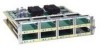
... the system detects the DTE mode cable, it to use the dce-terminal-timing-enable command to configure the DCE port to the remote DTE. Configuration commands are not supported for NRZI encoding or 32-bit CRC. This section describes how to set the clock speed with the clockrate configuration command. Network Connection Considerations Configuring the Four-Port Serial Module Interfaces The following example, the clock rate for the DCE device to generate its own...
... the system detects the DTE mode cable, it to use the dce-terminal-timing-enable command to configure the DCE port to the remote DTE. Configuration commands are not supported for NRZI encoding or 32-bit CRC. This section describes how to set the clock speed with the clockrate configuration command. Network Connection Considerations Configuring the Four-Port Serial Module Interfaces The following example, the clock rate for the DCE device to generate its own...

Hardware Maintenance Manual
Page 45
...-timing-enable command. NRZI uses differential encoding to the related software documentation. Before it receives from the remote DCE. The designator 16 indicates the number of the interface. Options to calculate the FCS. Use the no nrzi-encoding command. Configuring NRZI Format on the Four-Port Serial Module All Cisco 4000 series router serial interfaces support CRC-CCITT, a 16-bit cyclic redundancy check (CRC). To enable NRZI encoding on any interface, specify the port address...
...-timing-enable command. NRZI uses differential encoding to the related software documentation. Before it receives from the remote DCE. The designator 16 indicates the number of the interface. Options to calculate the FCS. Use the no nrzi-encoding command. Configuring NRZI Format on the Four-Port Serial Module All Cisco 4000 series router serial interfaces support CRC-CCITT, a 16-bit cyclic redundancy check (CRC). To enable NRZI encoding on any interface, specify the port address...
Hardware Maintenance Manual
Page 47
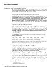
... single-attachment • Single-mode dual-attachment The multimode FDDI network processor module consists of two cards, each provide 11 dB of the single-mode network processor module (see Figure 2-24) use simplex FC-type connectors (see Figure 2-25). Network Connection Considerations Fiber Distributed Data Interface Connections Multimode FDDI network processor modules provide either a dual-attachment station (DAS) or a single-attachment station (SAS). Single-mode FDDI network processor modules provide a DAS. The...
... single-attachment • Single-mode dual-attachment The multimode FDDI network processor module consists of two cards, each provide 11 dB of the single-mode network processor module (see Figure 2-24) use simplex FC-type connectors (see Figure 2-25). Network Connection Considerations Fiber Distributed Data Interface Connections Multimode FDDI network processor modules provide either a dual-attachment station (DAS) or a single-attachment station (SAS). Single-mode FDDI network processor modules provide a DAS. The...
Hardware Maintenance Manual
Page 61
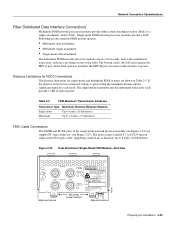
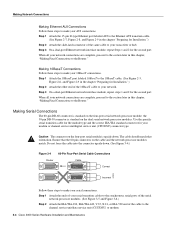
...transceiver Installing the Router 3-3 Figure 3-3 Unsupported and Supported Single-Port Ethernet Module Connections Unsupported configuration Ethernet module H1570a AUI 10BASE-T AUX Router (rear view) AUI 10BASE T AUX 10BaseT cable to Port 0, is supported. Making Network Connections Making Ethernet Connections Ethernet network processor modules contain both connectors on the same module. In Figure 3-2, the configuration on the port. For dual-port Ethernet modules (see Figure 3-3), connect either the Ethernet AUI connector or the 10BaseT connector on a specific Ethernet port, but...
...transceiver Installing the Router 3-3 Figure 3-3 Unsupported and Supported Single-Port Ethernet Module Connections Unsupported configuration Ethernet module H1570a AUI 10BASE-T AUX Router (rear view) AUI 10BASE T AUX 10BaseT cable to Port 0, is supported. Making Network Connections Making Ethernet Connections Ethernet network processor modules contain both connectors on the same module. In Figure 3-2, the configuration on the port. For dual-port Ethernet modules (see Figure 3-3), connect either the Ethernet AUI connector or the 10BaseT connector on a specific Ethernet port, but...
Hardware Maintenance Manual
Page 62
... "Preparing for Installation.") Step 2 Attach the other end of the cable to the channel service unit/data service unit (CSU/DSU) or modem. 3-4 Cisco 4000 Series Hardware Installation and Maintenance Step 3 On a dual-port Ethernet network interface module, repeat steps 1 and 2 for your modem or channel service unit/digital service unit (CSU/DSU) connector type. Making Serial Connections The 60-pin DB-60 connector is standard on the dual serial network processor modules. Step 1 Attach the 10BaseT port labeled 10BaseT...
... "Preparing for Installation.") Step 2 Attach the other end of the cable to the channel service unit/data service unit (CSU/DSU) or modem. 3-4 Cisco 4000 Series Hardware Installation and Maintenance Step 3 On a dual-port Ethernet network interface module, repeat steps 1 and 2 for your modem or channel service unit/digital service unit (CSU/DSU) connector type. Making Serial Connections The 60-pin DB-60 connector is standard on the dual serial network processor modules. Step 1 Attach the 10BaseT port labeled 10BaseT...
Hardware Maintenance Manual
Page 71
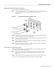
...-Mode FDDI Network Connections Connect a single-mode FDDI module as follows: Step 1 Connect the cable from the primary ring (from the secondary ring to the module's PHY- A transmit port labeled XMTR on the FDDI module panel. (See Figure 3-10 and Figure 3-11.) Step 2 Connect the other end of the optical bypass interface cable to the optical bypass switch. Connecting to an Optical Bypass Switch To connect the FDDI module to the module's PHY- Step 1 Connect...
...-Mode FDDI Network Connections Connect a single-mode FDDI module as follows: Step 1 Connect the cable from the primary ring (from the secondary ring to the module's PHY- A transmit port labeled XMTR on the FDDI module panel. (See Figure 3-10 and Figure 3-11.) Step 2 Connect the other end of the optical bypass interface cable to the optical bypass switch. Connecting to an Optical Bypass Switch To connect the FDDI module to the module's PHY- Step 1 Connect...
Hardware Maintenance Manual
Page 118
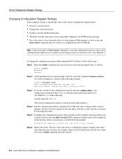
... image stored on or when you switch the power off and on a network server. (See Table B-3.) To change the configuration register while running the IOS software, follow : • Recover a lost password. • Change the console baud rate. • Enable or disable the Break function. • Manually boot the operating system using the b command at next reload) Step 6 Reboot the router. however, the new settings do not take effect only when the server restarts, for example...
... image stored on or when you switch the power off and on a network server. (See Table B-3.) To change the configuration register while running the IOS software, follow : • Recover a lost password. • Change the console baud rate. • Enable or disable the Break function. • Manually boot the operating system using the b command at next reload) Step 6 Reboot the router. however, the new settings do not take effect only when the server restarts, for example...

Hardware Maintenance Manual
Page 141
... C-2 preventing C-2 network activity indicator 4-4 connection considerations network processor module ATM 2-34 network processor modules dual serial 2-20 Ethernet 2-10 FDDI 2-27, 4-10 LED indicators 4-4 locations 5-6 removing 5-4 replacing 5-20 Token Ring 2-13 nonreturn to zero See NRZ nonreturn to zero-inverted See NRZI note, description xvi NRZ, configuring interface for NRZI, configuring interface for NT1 connection 3-6 numbering interfaces 2-7 slot positions 2-7 2-10 2-20 2-20 O o command (configuration register options) C-3 o/r command (reset) C-3 opening the chassis 5-1 operating...
... C-2 preventing C-2 network activity indicator 4-4 connection considerations network processor module ATM 2-34 network processor modules dual serial 2-20 Ethernet 2-10 FDDI 2-27, 4-10 LED indicators 4-4 locations 5-6 removing 5-4 replacing 5-20 Token Ring 2-13 nonreturn to zero See NRZ nonreturn to zero-inverted See NRZI note, description xvi NRZ, configuring interface for NRZI, configuring interface for NT1 connection 3-6 numbering interfaces 2-7 slot positions 2-7 2-10 2-20 2-20 O o command (configuration register options) C-3 o/r command (reset) C-3 opening the chassis 5-1 operating...


