
Hardware Maintenance Manual
Page 10
... 2-35 ATM Network Processor Module with STS-3c/STM-1 Multimode PLIM 2-35 Making Token Ring Connections 3-2 Making Dual-Ethernet Module Network Connections 3-3 Unsupported and Supported Single-Port Ethernet Module Connections 3-3 60-Pin Four-Port Serial Cable Connections 3-4 Making Serial Connections to the Four-Port Serial Module 3-5 Making Serial Connections to...15) 4-6 Serial Port Labeled V2 4-7 Dual Serial Network Processor Module-Top View 4-8 Dual Serial Port LED Card-Side View 4-8 Dual-Attachment Single-Mode FDDI Module-End View 4-9 x Cisco 4000 Series Hardware Installation and Maintenance
... 2-35 ATM Network Processor Module with STS-3c/STM-1 Multimode PLIM 2-35 Making Token Ring Connections 3-2 Making Dual-Ethernet Module Network Connections 3-3 Unsupported and Supported Single-Port Ethernet Module Connections 3-3 60-Pin Four-Port Serial Cable Connections 3-4 Making Serial Connections to the Four-Port Serial Module 3-5 Making Serial Connections to...15) 4-6 Serial Port Labeled V2 4-7 Dual Serial Network Processor Module-Top View 4-8 Dual Serial Port LED Card-Side View 4-8 Dual-Attachment Single-Mode FDDI Module-End View 4-9 x Cisco 4000 Series Hardware Installation and Maintenance

Hardware Maintenance Manual
Page 32
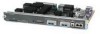
... follows: media-type aui media-type aui 10baset The following sections describe the two types of network connection available for a Cisco 4000 series router. end with DELETE, CTRL/W, and CTRL/U; Single-Port Ethernet Module Connections Each single-port Ethernet network processor module has an Ethernet...-port and dual-port modules. Selecting the Media Type The media type connection, AUI or 10BaseT, is not supported on the media command. 2-10 Cisco 4000 Series Hardware Installation and Maintenance Enter the media command in the router's configuration file to make the connection.
... follows: media-type aui media-type aui 10baset The following sections describe the two types of network connection available for a Cisco 4000 series router. end with DELETE, CTRL/W, and CTRL/U; Single-Port Ethernet Module Connections Each single-port Ethernet network processor module has an Ethernet...-port and dual-port modules. Selecting the Media Type The media type connection, AUI or 10BaseT, is not supported on the media command. 2-10 Cisco 4000 Series Hardware Installation and Maintenance Enter the media command in the router's configuration file to make the connection.

Hardware Maintenance Manual
Page 37
...449 signals to travel a limited distance at any given bit rate; The network end of the adapter cable is a standard 25-pin D-shell connector known as EIA/TIA-232. however, you can support 4-Mbps rates. If you understand the electrical problems that might arise and can ...at signal speeds up your own risk. EIA/TIA-232 Connections EIA/TIA-232, the most common interface standard in the United States, supports unbalanced circuits at your router, consider distance limitations and potential electromagnetic interference (EMI) as defined in Table 2-4. However, you may get good...
...449 signals to travel a limited distance at any given bit rate; The network end of the adapter cable is a standard 25-pin D-shell connector known as EIA/TIA-232. however, you can support 4-Mbps rates. If you understand the electrical problems that might arise and can ...at signal speeds up your own risk. EIA/TIA-232 Connections EIA/TIA-232, the most common interface standard in the United States, supports unbalanced circuits at your router, consider distance limitations and potential electromagnetic interference (EMI) as defined in Table 2-4. However, you may get good...
Hardware Maintenance Manual
Page 38
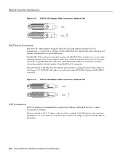
...of connections possible (fewer than possible with the smaller, 25-pin EIA/TIA-232 connector). The network end of the EIA/TIA-449 adapter cable provides a standard 37-pin D-shell connector. (See Figure ...hardware and because of the larger size of the 37-pin EIA/TIA-449 connectors, which supports balanced (EIA/TIA-422) and unbalanced (EIA/TIA-423) transmissions, is a faster (... which limited the number of EIA/TIA-232 that provides more functions and supports transmissions over greater distances. The network end of the V.35 adapter cable provides a standard 34-pin Winchester type connector...
...of connections possible (fewer than possible with the smaller, 25-pin EIA/TIA-232 connector). The network end of the EIA/TIA-449 adapter cable provides a standard 37-pin D-shell connector. (See Figure ...hardware and because of the larger size of the 37-pin EIA/TIA-449 connectors, which supports balanced (EIA/TIA-422) and unbalanced (EIA/TIA-423) transmissions, is a faster (... which limited the number of EIA/TIA-232 that provides more functions and supports transmissions over greater distances. The network end of the V.35 adapter cable provides a standard 34-pin Winchester type connector...
Hardware Maintenance Manual
Page 39
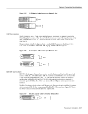
...available in the United Kingdom to connect public data networks. Figure 2-16 X.21 Adapter Cable Connectors, Network End 8 1 15 9 DTE DCE H1346a EIA-530 Connections EIA-530, which supports balanced transmission, provides the increased functionality, speed, and distance of EIA/TIA-449 on the smaller, ...and, as either DTE (DB-15 plug) or DCE (DB-15 receptacle). Network Connection Considerations Figure 2-15 V.35 Adapter Cable Connectors, Network End DTE DCE H1616a X.21 Connections The X.21 interface uses a 15-pin connection for balanced circuits and is a standard DB-15 connector. (See ...
...available in the United Kingdom to connect public data networks. Figure 2-16 X.21 Adapter Cable Connectors, Network End 8 1 15 9 DTE DCE H1346a EIA-530 Connections EIA-530, which supports balanced transmission, provides the increased functionality, speed, and distance of EIA/TIA-449 on the smaller, ...and, as either DTE (DB-15 plug) or DCE (DB-15 receptacle). Network Connection Considerations Figure 2-15 V.35 Adapter Cable Connectors, Network End DTE DCE H1616a X.21 Connections The X.21 interface uses a 15-pin connection for balanced circuits and is a standard DB-15 connector. (See ...
Hardware Maintenance Manual
Page 47
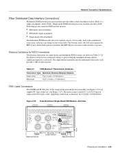
... (10 kilometers). The ports accept standard 8.7 to 10/125-micron single-mode fiber-optic cable, supporting connections at distances up to 1.2 miles (1.9 kilometers) FDDI Cable Connections The XMTR and RCVR ports ...FDDI network processor modules provide a DAS. Figure 2-24 Dual-Attachment Single-Mode FDDI Module-End View PHY-B XMTR PHY-A RCVR FDDI WARNING PHY-B RING OP PHY-A RING OP AVOID...EXPOSURE-INVISIBLE LASER RADIATION IS EMITTED FROM THESE APERTURES. 1300 NM CLASS 1 LASER PRODUCT LASERKLASSE 1 CISCO SYSTEMS, INC. 170 WEST TASMAN DRIVE SAN JOSE, CA 95134-1706 DATE: "Complies with one...
... (10 kilometers). The ports accept standard 8.7 to 10/125-micron single-mode fiber-optic cable, supporting connections at distances up to 1.2 miles (1.9 kilometers) FDDI Cable Connections The XMTR and RCVR ports ...FDDI network processor modules provide a DAS. Figure 2-24 Dual-Attachment Single-Mode FDDI Module-End View PHY-B XMTR PHY-A RCVR FDDI WARNING PHY-B RING OP PHY-A RING OP AVOID...EXPOSURE-INVISIBLE LASER RADIATION IS EMITTED FROM THESE APERTURES. 1300 NM CLASS 1 LASER PRODUCT LASERKLASSE 1 CISCO SYSTEMS, INC. 170 WEST TASMAN DRIVE SAN JOSE, CA 95134-1706 DATE: "Complies with one...
Hardware Maintenance Manual
Page 51
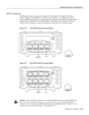
... carrier will provide the NT1 connection, except in the BRI cable. Each BRI port is customer owned. If you detach the BRI cable, detach the end away from the router first to an Integrated Services Digital Network (ISDN) through an ISDN channel service unit/digital service unit (CSU/DSU) called the..., where the NT1 is an RJ-45 8-pin connector. Network Connection Considerations BRI Connections The BRI network processor module (see Figure 2-31 and Figure 2-30) supports 8 Basic Rate Interface (BRI) ports.
... carrier will provide the NT1 connection, except in the BRI cable. Each BRI port is customer owned. If you detach the BRI cable, detach the end away from the router first to an Integrated Services Digital Network (ISDN) through an ISDN channel service unit/digital service unit (CSU/DSU) called the..., where the NT1 is an RJ-45 8-pin connector. Network Connection Considerations BRI Connections The BRI network processor module (see Figure 2-31 and Figure 2-30) supports 8 Basic Rate Interface (BRI) ports.

Hardware Maintenance Manual
Page 64
... OFF. (See Figure 3-7 and Figure 3-8.) The BRI network processor module supports point-to-point operation at an S interface (CCITT specification I.430 section 3.1). If you detach the BRI cable, detach the end away from such a condition could cause the router to it, must be... procedures are actively transmitting at any cable attached to shut down. The common carrier will "flap." The NT1 is customer owned. 3-6 Cisco 4000 Series Hardware Installation and Maintenance kHz = kilohertz. 2. The interrupts generated from the router first to the Router." If this chapter,...
... OFF. (See Figure 3-7 and Figure 3-8.) The BRI network processor module supports point-to-point operation at an S interface (CCITT specification I.430 section 3.1). If you detach the BRI cable, detach the end away from such a condition could cause the router to it, must be... procedures are actively transmitting at any cable attached to shut down. The common carrier will "flap." The NT1 is customer owned. 3-6 Cisco 4000 Series Hardware Installation and Maintenance kHz = kilohertz. 2. The interrupts generated from the router first to the Router." If this chapter,...
Hardware Maintenance Manual
Page 98
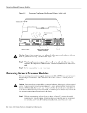
... component tray with your hand INPUT 100-240VAC 50/60HZ 3.0-1.5 AMPS Handle Warning Support the component tray from underneath, either on your hands, to prevent it from the top end of the network processor module, and the two external rear mounting screws (not shown) if the module has them,... and set the screws aside. 5-4 Cisco 4000 Series Hardware Installation and Maintenance Other types of the chassis shell....
... component tray with your hand INPUT 100-240VAC 50/60HZ 3.0-1.5 AMPS Handle Warning Support the component tray from underneath, either on your hands, to prevent it from the top end of the network processor module, and the two external rear mounting screws (not shown) if the module has them,... and set the screws aside. 5-4 Cisco 4000 Series Hardware Installation and Maintenance Other types of the chassis shell....
