
Hardware Maintenance Manual
Page 6
... Initial Hardware Configuration 4-1 Problem Solving 4-1 Troubleshooting the Power and Cooling Systems 4-2 Troubleshooting the Network Processor Modules and Cables 4-2 Environmental Reporting Features 4-3 Reading Front-Panel LED Indicators 4-3 System LED Operation 4-3 Reading Network Processor Module LED Indicators 4-4 Ethernet Network Processor Module LED Indicators ... Main Memory SIMMs 5-11 Replacing Shared-Memory SIMMs 5-13 Inserting Shared-Memory SIMMs 5-14 Removing the Cisco 4500-M and Cisco 4700 Boot Helper Flash Memory SIMM 5-16 Installing Flash-Memory SIMMs 5-17 Replacing Boot ROMs in the...
... Initial Hardware Configuration 4-1 Problem Solving 4-1 Troubleshooting the Power and Cooling Systems 4-2 Troubleshooting the Network Processor Modules and Cables 4-2 Environmental Reporting Features 4-3 Reading Front-Panel LED Indicators 4-3 System LED Operation 4-3 Reading Network Processor Module LED Indicators 4-4 Ethernet Network Processor Module LED Indicators ... Main Memory SIMMs 5-11 Replacing Shared-Memory SIMMs 5-13 Inserting Shared-Memory SIMMs 5-14 Removing the Cisco 4500-M and Cisco 4700 Boot Helper Flash Memory SIMM 5-16 Installing Flash-Memory SIMMs 5-17 Replacing Boot ROMs in the...

Hardware Maintenance Manual
Page 15
...is updated and shipped monthly, so it may be familiar with a DC-input power supply. Note To order UniverCD, Cisco's online library of the Cisco 4000 series features and physical specifications. • Chapter 2, "Preparing for Installation," includes safety recommendations, tools and equipment, site requirements,...Series Overview," contains an overview of product information, or printed publications, refer to install and maintain the Cisco 4000-M, Cisco 4500-M, and the Cisco 4700. To order UniverCD, contact your warranty package. Audience This publication is available both as a ...
...is updated and shipped monthly, so it may be familiar with a DC-input power supply. Note To order UniverCD, Cisco's online library of the Cisco 4000 series features and physical specifications. • Chapter 2, "Preparing for Installation," includes safety recommendations, tools and equipment, site requirements,...Series Overview," contains an overview of product information, or printed publications, refer to install and maintain the Cisco 4000-M, Cisco 4500-M, and the Cisco 4700. To order UniverCD, contact your warranty package. Audience This publication is available both as a ...

Hardware Maintenance Manual
Page 16
...Conventions • Chapter 4, "Troubleshooting the Initial Hardware Configuration," includes a troubleshooting overview, problem-solving instructions, environmental reporting features, and understanding front-panel and network-processor module LED indicators. • Chapter 5, "Maintaining and Upgrading the Router...in screen font, with default responses in this manual. You can be used. • Appendix D, "Cisco 4500-M and Cisco 4700 ROM Monitor," describes the Cisco 4500 ROM monitor. • Appendix E, "Operating Conditions for the United Kingdom," describes the operating conditions for...
...Conventions • Chapter 4, "Troubleshooting the Initial Hardware Configuration," includes a troubleshooting overview, problem-solving instructions, environmental reporting features, and understanding front-panel and network-processor module LED indicators. • Chapter 5, "Maintaining and Upgrading the Router...in screen font, with default responses in this manual. You can be used. • Appendix D, "Cisco 4500-M and Cisco 4700 ROM Monitor," describes the Cisco 4500 ROM monitor. • Appendix E, "Operating Conditions for the United Kingdom," describes the operating conditions for...

Hardware Maintenance Manual
Page 26
...supply: • Autoranging power supply (200W, 85 to 264 VAC or 40 to 72 VDC, 50 to 60 Hz) • 6-foot electrical power cord 2-4 Cisco 4000 Series Hardware Installation and Maintenance Equipment Racks The following precautions will help you plan an acceptable operating environment for your router and will help... a maximum of the next. • Always follow the ESD-prevention procedures in the top, excessive heat generated by itself, if possible. Power Supply Features Following are features of the equipment above. • Baffles can be adequate to cool equipment to flow within.
...supply: • Autoranging power supply (200W, 85 to 264 VAC or 40 to 72 VDC, 50 to 60 Hz) • 6-foot electrical power cord 2-4 Cisco 4000 Series Hardware Installation and Maintenance Equipment Racks The following precautions will help you plan an acceptable operating environment for your router and will help... a maximum of the next. • Always follow the ESD-prevention procedures in the top, excessive heat generated by itself, if possible. Power Supply Features Following are features of the equipment above. • Baffles can be adequate to cool equipment to flow within.

Hardware Maintenance Manual
Page 81
... of the problem you cannot locate the source of isolating a problem is doing , the task of your system, follow : • Problem Solving • Environmental Reporting Features • Reading Front-Panel LED Indicators • Reading Network Processor Module LED Indicators Use the information in before leaving the factory. If you are problems...
... of the problem you cannot locate the source of isolating a problem is doing , the task of your system, follow : • Problem Solving • Environmental Reporting Features • Reading Front-Panel LED Indicators • Reading Network Processor Module LED Indicators Use the information in before leaving the factory. If you are problems...

Hardware Maintenance Manual
Page 83
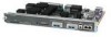
... the console screen: %SYS-1-OVERTEMP: System detected OVERTEMPERATURE condition. Please resolve cooling problem immediately! Environmental Reporting Features • System boots, but console screen is operating at a glance. Environmental Reporting Features If the router is frozen. - Figure 4-1 Cisco 4000 Series-Front Panel Indicators Network activity LEDs Run LED 1 DATA OK 2 DATA OK Health LEDs...
... the console screen: %SYS-1-OVERTEMP: System detected OVERTEMPERATURE condition. Please resolve cooling problem immediately! Environmental Reporting Features • System boots, but console screen is operating at a glance. Environmental Reporting Features If the router is frozen. - Figure 4-1 Cisco 4000 Series-Front Panel Indicators Network activity LEDs Run LED 1 DATA OK 2 DATA OK Health LEDs...

Hardware Maintenance Manual
Page 127
...always enabled for 60 seconds after the router is configured to 0x0 by setting the configuration register. The Cisco 4500-M and Cisco 4700 ROM monitor supports more features than the familiar Cisco 4000-M ROM monitor. An example of the ROM monitor diagnostic tests and command options is powered-up or... router in the standalone ROM monitor. The ROM Monitor can break to run when the router is provided. Cisco 4500-M and Cisco 4700 ROM Monitor D-1 A summary of the Cisco 4500-M and Cisco 4700 ROM monitor prompt follows: rommon 1 > To enable the Break key, and to default to booting...
...always enabled for 60 seconds after the router is configured to 0x0 by setting the configuration register. The Cisco 4500-M and Cisco 4700 ROM monitor supports more features than the familiar Cisco 4000-M ROM monitor. An example of the ROM monitor diagnostic tests and command options is powered-up or... router in the standalone ROM monitor. The ROM Monitor can break to run when the router is provided. Cisco 4500-M and Cisco 4700 ROM Monitor D-1 A summary of the Cisco 4500-M and Cisco 4700 ROM monitor prompt follows: rommon 1 > To enable the Break key, and to default to booting...

Hardware Maintenance Manual
Page 141
... four-port A-11 X.21 dual-port A-14 four-port A-15 polarity, Ethernet LED 4-5 port locations 2-7 software configuration, serial 4-8 power LED indication 3-22 light 4-3 specifications 1-3 supply features 2-4 system, troubleshooting 4-2 preparing for installation 2-1 to make connections 2-7 preventing ESD damage 2-3 preventive site configuration 2-4 printing summary of ROM monitor commands problem indications 4-3 temperature 4-3 problem solving...
... four-port A-11 X.21 dual-port A-14 four-port A-15 polarity, Ethernet LED 4-5 port locations 2-7 software configuration, serial 4-8 power LED indication 3-22 light 4-3 specifications 1-3 supply features 2-4 system, troubleshooting 4-2 preparing for installation 2-1 to make connections 2-7 preventing ESD damage 2-3 preventive site configuration 2-4 printing summary of ROM monitor commands problem indications 4-3 temperature 4-3 problem solving...
