
Hardware Maintenance Manual
Page 9
... 2-21 Figure 2-22 Figure 2-23 Figure 2-24 Figure 2-25 Figure 2-26 Figure 2-27 Figure 2-28 Figure 2-29 Figure 2-30 Figure 2-31 Figure 2-32 Cisco 4000 Series Chassis-Front Panel 1-2 Cisco 4000 Series Memory Systems and Software Images 1-4 Installation Checklist 2-5 Router-Rear View Showing Slot Numbering and Interface Ports 2-7 Router-Rear View Showing Serial...
... 2-21 Figure 2-22 Figure 2-23 Figure 2-24 Figure 2-25 Figure 2-26 Figure 2-27 Figure 2-28 Figure 2-29 Figure 2-30 Figure 2-31 Figure 2-32 Cisco 4000 Series Chassis-Front Panel 1-2 Cisco 4000 Series Memory Systems and Software Images 1-4 Installation Checklist 2-5 Router-Rear View Showing Slot Numbering and Interface Ports 2-7 Router-Rear View Showing Serial...

Hardware Maintenance Manual
Page 11
... with STS-3c/STM-1 Multimode PLIM 4-14 Component Tray Removal for Chassis With a Safety Latch 5-3 Component Tray Removal for Chassis Without a Safety Latch 5-4 Typical Cisco 4000 Series Component Tray-Cisco 4000-M Shown 5-5 Network Processor Module Locations 5-6 Cisco 4000-M SIMM Locations 5-7 Cisco 4500-M and Cisco 4700 SIMM Locations 5-8 Cisco 4000 Series Main Memory SIMM 5-8 Removing Main Memory SIMMs 5-10...
... with STS-3c/STM-1 Multimode PLIM 4-14 Component Tray Removal for Chassis With a Safety Latch 5-3 Component Tray Removal for Chassis Without a Safety Latch 5-4 Typical Cisco 4000 Series Component Tray-Cisco 4000-M Shown 5-5 Network Processor Module Locations 5-6 Cisco 4000-M SIMM Locations 5-7 Cisco 4500-M and Cisco 4700 SIMM Locations 5-8 Cisco 4000 Series Main Memory SIMM 5-8 Removing Main Memory SIMMs 5-10...

Hardware Maintenance Manual
Page 16
...panel and network-processor module LED indicators. • Chapter 5, "Maintaining and Upgrading the Router," includes instructions for opening the chassis, replacing or adding network processor modules, and replacing single in-line memory modules (SIMMs). • Appendix A, "Cabling Specifications...) cables. • Appendix B, "Cisco 4000 Series Virtual Configuration Register," describes the Cisco 4000-M virtual configuration register and procedures for changing the factory-default settings. • Appendix C, "Cisco 4000-M ROM Monitor," describes the Cisco 4000-M ROM monitor and how it can...
...panel and network-processor module LED indicators. • Chapter 5, "Maintaining and Upgrading the Router," includes instructions for opening the chassis, replacing or adding network processor modules, and replacing single in-line memory modules (SIMMs). • Appendix A, "Cabling Specifications...) cables. • Appendix B, "Cisco 4000 Series Virtual Configuration Register," describes the Cisco 4000-M virtual configuration register and procedures for changing the factory-default settings. • Appendix C, "Cisco 4000-M ROM Monitor," describes the Cisco 4000-M ROM monitor and how it can...

Hardware Maintenance Manual
Page 19
... in the router are all labeled Cisco 4000 Series on the chassis rear. and the Cisco 4000-M contains a 40-MHz Motorola 68EC030 microprocessor. External Differences in the Cisco 4000 series, the Cisco 4700 contains a 133-MHz Orion RISC microprocessor from IDT; CHAPTER 1 Cisco 4000 Series Overview The Cisco 4000 series comprises the Cisco 4000-M, the Cisco 4500-M, and the...
... in the router are all labeled Cisco 4000 Series on the chassis rear. and the Cisco 4000-M contains a 40-MHz Motorola 68EC030 microprocessor. External Differences in the Cisco 4000 series, the Cisco 4700 contains a 133-MHz Orion RISC microprocessor from IDT; CHAPTER 1 Cisco 4000 Series Overview The Cisco 4000 series comprises the Cisco 4000-M, the Cisco 4500-M, and the...

Hardware Maintenance Manual
Page 20
...-8B) are not compatible with the Channelized T1/ISDN PRI network interface module (NP-CT1) or with any desired combination. Figure 1-1 Cisco 4000 Series Chassis-Front Panel 1 DATA OK 2 DATA OK 3 DATA OK OK POWER SERIES H3590 Series Specifications Design specifications for the... Cisco 4000 series follow: • Modular router platform • Flash memory capability • User-upgradable network processor modules, shared memory, and processor ...
...-8B) are not compatible with the Channelized T1/ISDN PRI network interface module (NP-CT1) or with any desired combination. Figure 1-1 Cisco 4000 Series Chassis-Front Panel 1 DATA OK 2 DATA OK 3 DATA OK OK POWER SERIES H3590 Series Specifications Design specifications for the... Cisco 4000 series follow: • Modular router platform • Flash memory capability • User-upgradable network processor modules, shared memory, and processor ...

Hardware Maintenance Manual
Page 21
...). The Orion microprocessor is based on the MIPS R4400 and is pin-compatible. 2. Table 1-1 Cisco 4000 Series Physical Specifications Description Design Specification Dimensions (W x D x H) 17.6" x 17.7" x 3.4" (44.7 cm x 45 cm x 8.6 cm) Weight 24 lb (10.9 kg) (including the chassis and network processor modules) Power Wire Gauge for DC-Input Power Connections 200W, 85...
...). The Orion microprocessor is based on the MIPS R4400 and is pin-compatible. 2. Table 1-1 Cisco 4000 Series Physical Specifications Description Design Specification Dimensions (W x D x H) 17.6" x 17.7" x 3.4" (44.7 cm x 45 cm x 8.6 cm) Weight 24 lb (10.9 kg) (including the chassis and network processor modules) Power Wire Gauge for DC-Input Power Connections 200W, 85...
Hardware Maintenance Manual
Page 24
...not wear loose clothing that creates a potential hazard to get caught in the chassis. If possible, send another person to people or makes the equipment unsafe. then take appropriate action. 2-2 Cisco 4000 Series Hardware Installation and Maintenance Fasten your tie or scarf and roll up ...follows: - Then, if an electrical accident occurs, you are working on the system, turn all power before opening the chassis. • Keep tools and chassis components away from a circuit. Otherwise, assess the victim's condition and then call for possible hazards in which you can ...
...not wear loose clothing that creates a potential hazard to get caught in the chassis. If possible, send another person to people or makes the equipment unsafe. then take appropriate action. 2-2 Cisco 4000 Series Hardware Installation and Maintenance Fasten your tie or scarf and roll up ...follows: - Then, if an electrical accident occurs, you are working on the system, turn all power before opening the chassis. • Keep tools and chassis components away from a circuit. Otherwise, assess the victim's condition and then call for possible hazards in which you can ...

Hardware Maintenance Manual
Page 25
... designed for safe installation and operation of your site layout and equipment locations, use the rubber feet provided. They protect the chassis and provide a nonskid surface. When planning your system. General Site Requirements This section describes the requirements your site must operate ... but still connected to earth ground. If you isolate the cause of environmentally caused shutdowns. Connect the clip to an unpainted chassis frame surface to safely channel unwanted ESD voltages to help you are extremely important for Installation 2-3 For desktop mounting, use the...
... designed for safe installation and operation of your site layout and equipment locations, use the rubber feet provided. They protect the chassis and provide a nonskid surface. When planning your system. General Site Requirements This section describes the requirements your site must operate ... but still connected to earth ground. If you isolate the cause of environmentally caused shutdowns. Connect the clip to an unpainted chassis frame surface to safely channel unwanted ESD voltages to help you are extremely important for Installation 2-3 For desktop mounting, use the...

Hardware Maintenance Manual
Page 26
...to allow cooling air to ensure that the room in which may in adjacent racks) to avoid damage from one chassis can be adequate to cool equipment to acceptable operating temperatures without adequate circulation. Turn off other equipment in the ...chassis side by side because the heated exhaust air from lightning and power surges. General Site Requirements Site Configuration Precautions The following tips will help you plan an acceptable equipment rack configuration: • Enclosed racks must have louvered sides and a fan to 60 Hz) • 6-foot electrical power cord 2-4 Cisco...
...to allow cooling air to ensure that the room in which may in adjacent racks) to avoid damage from one chassis can be adequate to cool equipment to acceptable operating temperatures without adequate circulation. Turn off other equipment in the ...chassis side by side because the heated exhaust air from lightning and power surges. General Site Requirements Site Configuration Precautions The following tips will help you plan an acceptable equipment rack configuration: • Enclosed racks must have louvered sides and a fan to 60 Hz) • 6-foot electrical power cord 2-4 Cisco...

Hardware Maintenance Manual
Page 27
... check completed Required tools available Additional equipment available Router received Printed documentation or UniverCD received (if ordered) Product registration (in warranty package) completed and mailed Chassis components verified Software version verified Initial electrical connections established ASCII terminal attached to console port Signal distance limits verified Startup sequence steps completed Initial system...
... check completed Required tools available Additional equipment available Router received Printed documentation or UniverCD received (if ordered) Product registration (in warranty package) completed and mailed Chassis components verified Software version verified Initial electrical connections established ASCII terminal attached to console port Signal distance limits verified Startup sequence steps completed Initial system...

Hardware Maintenance Manual
Page 28
... Number 2 Phillips • One serial port adapter cable for multimode Fiber Distributed Data Interface (FDDI) connections. 2-6 Cisco 4000 Series Hardware Installation and Maintenance Use the Installation Checklist to verify steps in a common place near the chassis where anyone who performs tasks has access to connect the port with the remote device or...
... Number 2 Phillips • One serial port adapter cable for multimode Fiber Distributed Data Interface (FDDI) connections. 2-6 Cisco 4000 Series Hardware Installation and Maintenance Use the Installation Checklist to verify steps in a common place near the chassis where anyone who performs tasks has access to connect the port with the remote device or...

Hardware Maintenance Manual
Page 29
... cable and switch. (See Figure 2-2.) Figure 2-2 Router-Rear View Showing Slot Numbering and Interface Ports Slot 3 Token Ring port 10BaseT Chassis Serial interface ports port release screw Slot 1 Ethernet port Slot 2 Dual serial module H1033a Token Ring module Ethernet module Auxiliary port Console ...port Power On/off switch Slot Numbering The chassis contains slots for the FDDI module if one is present. Network processor module location is the module closest to the power supply. ...
... cable and switch. (See Figure 2-2.) Figure 2-2 Router-Rear View Showing Slot Numbering and Interface Ports Slot 3 Token Ring port 10BaseT Chassis Serial interface ports port release screw Slot 1 Ethernet port Slot 2 Dual serial module H1033a Token Ring module Ethernet module Auxiliary port Console ...port Power On/off switch Slot Numbering The chassis contains slots for the FDDI module if one is present. Network processor module location is the module closest to the power supply. ...
Hardware Maintenance Manual
Page 30
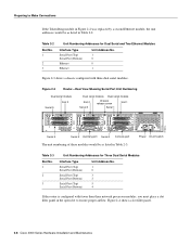
... Two Ethernet Modules Interface Type Serial Port (Top) Serial Port (Bottom) Ethernet Ethernet Unit Address No. 1 0 0 1 Figure 2-3 shows a chassis configured with fewer than three network processor modules, you must place a slot filler panel in the open slot to Make Connections If the Token Ring... module in Figure 2-2 was replaced by a second Ethernet module, the unit addresses would be as listed in Table 2-2. H1402 a 2-8 Cisco 4000 Series Hardware Installation and Maintenance Preparing to ensure proper airflow. Table 2-2 Slot No. 1 2 3 Unit Numbering Addresses for Three Dual...
... Two Ethernet Modules Interface Type Serial Port (Top) Serial Port (Bottom) Ethernet Ethernet Unit Address No. 1 0 0 1 Figure 2-3 shows a chassis configured with fewer than three network processor modules, you must place a slot filler panel in the open slot to Make Connections If the Token Ring... module in Figure 2-2 was replaced by a second Ethernet module, the unit addresses would be as listed in Table 2-2. H1402 a 2-8 Cisco 4000 Series Hardware Installation and Maintenance Preparing to ensure proper airflow. Table 2-2 Slot No. 1 2 3 Unit Numbering Addresses for Three Dual...

Hardware Maintenance Manual
Page 31
In the appendix "Cabling Specifications," Table A-1 lists the pinout for the Cisco 4000-M and Table A-2 lists the pinout for Installation 2-9 Auxiliary Port Connections A male DB-25 connector auxiliary port (labeled AUX on the chassis rear) is a shared-memory data terminal equipment (DTE) port to which you can attach an EIA/TIA-232 connector...
In the appendix "Cabling Specifications," Table A-1 lists the pinout for the Cisco 4000-M and Table A-2 lists the pinout for Installation 2-9 Auxiliary Port Connections A male DB-25 connector auxiliary port (labeled AUX on the chassis rear) is a shared-memory data terminal equipment (DTE) port to which you can attach an EIA/TIA-232 connector...

Hardware Maintenance Manual
Page 43
.... and EIA-530 DTE. Nine different serial cables are not interchangeable. Figure 2-23 Router Serial Cable Connections Serial port 50-pin connector Serial transition cable Chassis H1037a EIA/TIA-232, EIA/TIA-449, V.35, X.21, or EIA-530 connector Modem or CSU/DSU Note Serial ports configured as shown in Figure...
.... and EIA-530 DTE. Nine different serial cables are not interchangeable. Figure 2-23 Router Serial Cable Connections Serial port 50-pin connector Serial transition cable Chassis H1037a EIA/TIA-232, EIA/TIA-449, V.35, X.21, or EIA-530 connector Modem or CSU/DSU Note Serial ports configured as shown in Figure...
Hardware Maintenance Manual
Page 48
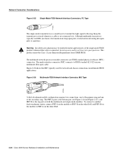
... small laser to transmit the light signal to the secondary ring. Although multimode transceivers typically use LEDs (not lasers) for network and chassis connections in multimode FDDI applications. Avoid exposure and do not stare into open apertures. Figure 2-26 shows the MIC typically used for ...the ring. To connect to another dual-attachment station, connect PHY-A on the module to PHY-B on the other DAS. 2-26 Cisco 4000 Series Hardware Installation and Maintenance H1349a The media interface connector (MIC) connects to PHY-A on both the multimode and single-mode modules...
... small laser to transmit the light signal to the secondary ring. Although multimode transceivers typically use LEDs (not lasers) for network and chassis connections in multimode FDDI applications. Avoid exposure and do not stare into open apertures. Figure 2-26 shows the MIC typically used for ...the ring. To connect to another dual-attachment station, connect PHY-A on the module to PHY-B on the other DAS. 2-26 Cisco 4000 Series Hardware Installation and Maintenance H1349a The media interface connector (MIC) connects to PHY-A on both the multimode and single-mode modules...

Hardware Maintenance Manual
Page 54
...Connection Considerations Channelized E1 Connections The Cisco 4000 series router supports a channelized E1 (CE1) network processor module with capacitive coupling between the transmit (Tx) shield and chassis ground, set capacitive coupling between the receive (Rx) shield and chassis ground. Each virtual channel is ... provides up to a channel service unit (CSU). This provides direct current (DC) isolation between the transmit or receive shield and chassis ground, and the cable resistance (120-ohm or 75-ohm). This interface is presented to the system as a serial interface that...
...Connection Considerations Channelized E1 Connections The Cisco 4000 series router supports a channelized E1 (CE1) network processor module with capacitive coupling between the transmit (Tx) shield and chassis ground, set capacitive coupling between the receive (Rx) shield and chassis ground. Each virtual channel is ... provides up to a channel service unit (CSU). This provides direct current (DC) isolation between the transmit or receive shield and chassis ground, and the cable resistance (120-ohm or 75-ohm). This interface is presented to the system as a serial interface that...

Hardware Maintenance Manual
Page 55
...Cabling Table 2-7 Jumper Settings and Functions Jumper Position Function J2 1 and 2 Connects the Rx shield to chassis ground. 2 and 3 Connects the Rx shield through capacitive coupling to chassis ground. Figure 2-35 Location of severe injury. All of these jumpers must be configured by trained service personnel... thereby coupling the interface directly to reduce the potential for Installation 2-33 For the CE1 module, four serial cables are available from Cisco Systems. All three have DB-15 connectors on the network end. By default and for safety, J2 has been configured with BNC ...
...Cabling Table 2-7 Jumper Settings and Functions Jumper Position Function J2 1 and 2 Connects the Rx shield to chassis ground. 2 and 3 Connects the Rx shield through capacitive coupling to chassis ground. Figure 2-35 Location of severe injury. All of these jumpers must be configured by trained service personnel... thereby coupling the interface directly to reduce the potential for Installation 2-33 For the CE1 module, four serial cables are available from Cisco Systems. All three have DB-15 connectors on the network end. By default and for safety, J2 has been configured with BNC ...

Hardware Maintenance Manual
Page 58
... appears damaged, or if you want the system installed, proceed with the unpacking. Inspecting the System Note The ATM processor module for the Cisco 4000 series router uses identical duplex SC connectors for desktop mounting • Optional equipment (which might be emitted from CDRH FDDI. If the... Registration (found in its shipping container to install it. The best way to tell the difference is not ready, keep the chassis in the Warranty Package). 2-36 Cisco 4000 Series Hardware Installation and Maintenance The front panels are prepared to prevent accidental damage.
... appears damaged, or if you want the system installed, proceed with the unpacking. Inspecting the System Note The ATM processor module for the Cisco 4000 series router uses identical duplex SC connectors for desktop mounting • Optional equipment (which might be emitted from CDRH FDDI. If the... Registration (found in its shipping container to install it. The best way to tell the difference is not ready, keep the chassis in the Warranty Package). 2-36 Cisco 4000 Series Hardware Installation and Maintenance The front panels are prepared to prevent accidental damage.
Hardware Maintenance Manual
Page 59
... console port, and you must perform to install your cable connection requires it, the jackscrews can be mounted directly above another chassis in the separate rack-mount/wall-mount publication included with optional rubber "feet." The console port and auxiliary ports have jackscrews ...Final Connections to be removed. The procedures for the different mounting options involve removing the front panel and component tray from the chassis shell and then installing the empty shell in position before making the network and power connections while following the procedures described in...
... console port, and you must perform to install your cable connection requires it, the jackscrews can be mounted directly above another chassis in the separate rack-mount/wall-mount publication included with optional rubber "feet." The console port and auxiliary ports have jackscrews ...Final Connections to be removed. The procedures for the different mounting options involve removing the front panel and component tray from the chassis shell and then installing the empty shell in position before making the network and power connections while following the procedures described in...